
Flow Dynamics at the Sealing Boundary: Why Micro-Recesses and Gland Cavities Trap Process Residue
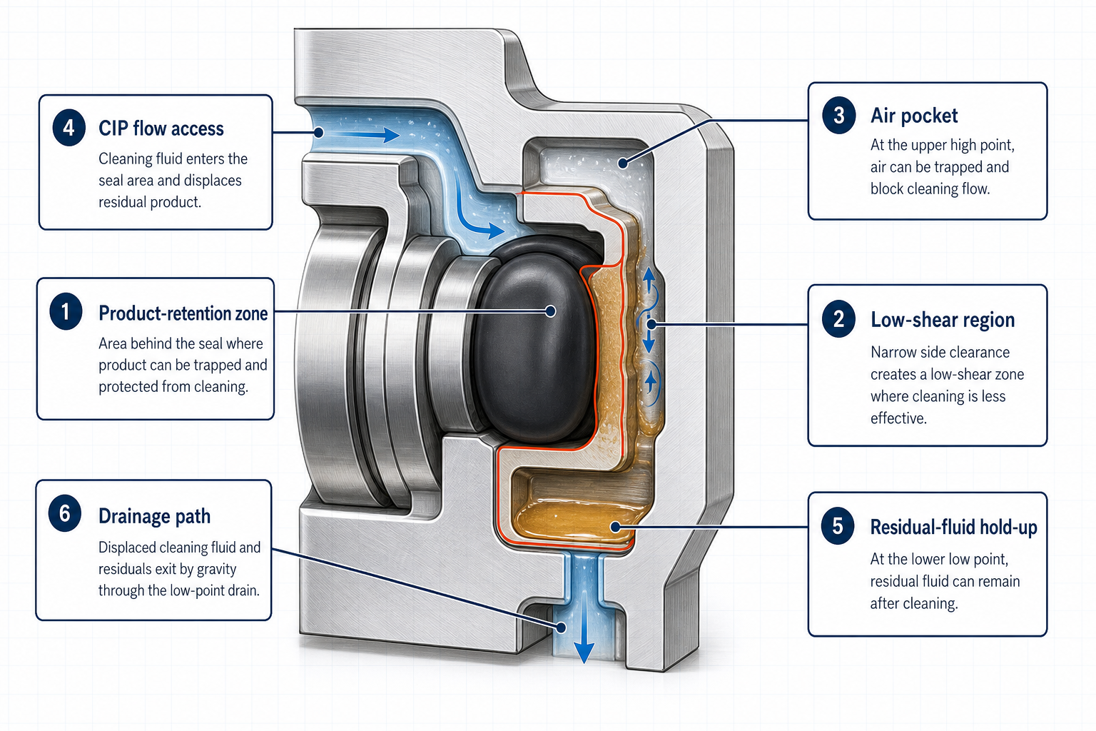
In sanitary and aseptic fluid transfer systems, an elastomer seal groove is never a purely static mechanical boundary. It operates simultaneously as a hydrodynamic interface, a thermal expansion relief pocket, a local shear-stress boundary, and a primary drainage conduit. During standard food, dairy, beverage, and biopharmaceutical processing, fluid boundary layers decelerate near housing walls. When internal flow encounters an open seal gland or uncompressed clearance gap, local velocity drops precipitously toward stagnation. This micro-recess phenomenon transforms what appears to be a sealed joint into an active product-retention pocket where dairy fats, proteins, sugars, and cellular debris migrate under pressure fluctuations and shaft runout.
Standard clean-in-place (CIP) regimens rely on turbulent scouring, chemical saponification, and acidic dissolution to clean process lines. However, bulk fluid turbulence in the main pump casing does not guarantee penetration into narrow gland side clearances. If local wall shear stress within the groove recess fails to exceed the critical adhesive and cohesive yield stress of the deposited product film, residue remains trapped beneath bulk flow. The consequence is biological cross-contamination, non-sterility in downstream batches, allergen carryover, and localized under-deposit corrosion. Eliminating retention zones requires precise coordination between seal gland geometry, controlled elastomer compression, boundary wall shear generation, self-draining orientation, and multi-stage residue detection.
Hygienic Gland Architecture: Comparing Open, Semi-Closed, and Defined-Compression Seal Pockets
Dead-Volume Elimination via Controlled Gland Fill Factor
The geometric configuration of the seal cavity dictates whether cleaning fluid can wet and scour the sealing interface. In standard industrial pumps, deep rectangular O-ring grooves provide 20% to 30% void volume to prevent elastomer over-compression. In hygienic service, excessive void volume creates an expansive annular dead space where process fluid stagnates. When transitioning to CIP, cleaning solution skims across the top of the open void, leaving an unmixed stagnant eddy within the gland base.
Corner Radius Optimization for Turbulent Penetration
To solve this vulnerability, hygienic engineering utilizes three distinct gland architectures: open radius profiles, semi-closed controlled-compression pockets, and defined metal-to-metal stop flush seals. Open radius glands replace 90-degree internal corners with smooth transitions (R ≥ 1.5 mm), allowing turbulent eddies to penetrate directly to the gland root. Semi-closed profiles feature angled sidewalls (15° to 30°) that prevent product wedge formation while ensuring positive elastomer retention. Metal-to-metal mechanical stops constrain elastomer deformation to exactly 15% to 22% radial squeeze, completely filling the inner pocket while presenting a flush, seamless contact profile to the process stream.
Table 1 – Hygienic Seal-Groove Geometries and Hydrodynamic Cleanability Metrics
| Gland Architecture | Geometry Features & Corner Radii | Gland Fill Range (%) | Flow Penetration Index | Cleaning Mechanism | Primary Risk Factor |
| Standard Rectangular | 90° sharp corners, R < 0.4 mm, parallel sidewalls | 70% – 80% | Poor (< 0.2) | Diffusive dilution only | Soil compaction in root corners |
| Hygienic Open Radius | 15° angled walls, R ≥ 1.5 mm, blended root | 85% – 92% | Excellent (> 0.8) | Direct wall shear scouring | Dynamic seal lip dislodgement |
| Controlled Compression | Mechanical metal stop, R ≥ 0.8 mm, trapped volume | 92% – 96% | High (0.6 – 0.8) | Vortex boundary renewal | Gland gap extrusion under surge |
| Flush Lip Profile | Front-face seal line, zero internal cavity | 95% – 99% | Maximum (> 0.95) | Continuous stream washing | Thermal overfill pinching |
Physical Mechanisms of Soil Retention and Cleaning Dead Spots in Pump Cavities
Low-Shear Recirculation and Fluid Shadowing
Product retention occurs through three discrete physical mechanisms: low-shear recirculation eddies, capillary infiltration behind unbonded elastomeric faces, and geometric shadowing behind high-profile seal shoulders. When process media flows past an open gland, boundary layer separation generates a slow-rotating vortex. Fluid velocity inside this vortex drops below 0.1 m/s, preventing the generation of wall shear stress necessary to break biological biofilms (wall shear stress ≥ 1.5 Pa).
Capillary Wicking, Soil Caking, and Thermal Denaturation
Capillary infiltration occurs when low-viscosity fluids penetrate the dynamic micro-gap between elastomer and metal. Under thermal processing or hot sanitization, trapped sugars crystallize and proteins denature, forming hardened deposits that resist chemical dissolution. Furthermore, air pockets trapped at high gland locations during pre-rinse prevent aqueous CIP chemicals from contacting metal surfaces, resulting in un-sanitized dry spots.
Table 2 – Soil Retention and Dead-Spot Mechanisms in Hygienic Seal Grooves
| Retention Mechanism | Primary Gland Location | Hydrodynamic Root Cause | Physical Soil State | Diagnostic & Verification Method |
| Low-Shear Eddy Stagnation | Seal backside and deep gland corners | Local wall shear stress < 0.5 Pa | Liquid pooling and gelatinous film | CFD velocity modeling & dye washout |
| Capillary Micro-Infiltration | Elastomer-metal dynamic interface | Interfacial gap wicking under 0.6 MPa | Crystallized sugars and dried salts | Optical disassembly microscopy |
| Air Pocket Shielding | High-point vertical seal cavities | Buoyancy entrapment during pre-rinse | Un-wetted native product film | Riboflavin fluorescent inspection |
| Thermal Soil Denaturation | Shaft seal frictional contact zones | Interface hot-spotting (> 85°C) | Cross-linked baked protein crust | Total Organic Carbon (TOC) swab |
| Particulate Hold-up | Narrow side clearances (< 0.2 mm) | Steric entrapment of fibers/solids | Agglomerated particulate cake | Gravimetric post-CIP flush audit |
Hydrodynamic Cleaning Parameters: Wall Shear Stress, Flow Velocity, and Chemical Exchange Kinetics
Wall Shear Stress Thresholds and Minimum Velocity Criteria
CIP effectiveness is governed by five interdependent parameters: fluid velocity, wall shear stress, chemical concentration, solution temperature, and contact exposure time. In bulk pipework, maintaining a flow velocity of 1.5 m/s to 2.0 m/s generates adequate Reynolds numbers (Re > 10,000) for general surface cleaning. However, inside recessed seal cavities, local velocity diminishes rapidly. Engineering guidelines require designing pump internal passages such that minimum local wall shear stress within seal pockets exceeds 1.5 Pa to 2.0 Pa during forward and reverse CIP flushing.
Mass Transfer Rates and Chemical Boundary Layer Renewal
Chemical cleaning kinetics depend on continuous renewal of active cleaning agents (typically 1.0% to 2.0% sodium hydroxide for organic soil saponification, followed by 0.5% to 1.0% nitric or phosphoric acid for mineral descaling). In dead-spot geometries, chemical diffusion limits reaction rates. Pulsed CIP flow profiles and periodic air-injection slug flow introduce rapid pressure transients (ΔP = 0.05 MPa to 0.15 MPa) that disrupt stagnant boundary layers, accelerating mass transfer and reducing required cleaning cycles.
Table 3 – CIP/SIP Operational Parameters and Seal-Groove Hydrodynamic Response
| Operational Parameter | Target CIP Operating Range | Micro-Gland Physical Impact | Failure Mode / Risk | Yokey Engineering Mitigation |
| CIP Flow Velocity | 1.5 – 2.5 m/s casing velocity | Transfers kinetic energy to groove entrance | Low wall shear stress (< 1.0 Pa) | Smooth 15° angled lead-in chamfers |
| Local Wall Shear Stress | Wall shear stress ≥ 2.0 Pa across all surfaces | Mechanical detachment of adhesive soils | Biofilm adhesion & scaling | CFD-optimized groove shallow depth |
| Chemical Caustic Wash | 1.0% – 2.0% NaOH at 65°C – 80°C | Saponification of fatty acids and lipids | Elastomer chemical embrittlement | EPDM/FKM sanitary grade specification |
| Acid Descaling Cycle | 0.5% – 1.0% HNO3 at 50°C – 65°C | Dissolution of mineral and milkstone scales | Corrosion pitting in 316L SS | Electropolished gland root (Ra ≤ 0.4 μm) |
| SIP Steam Exposure | 121°C – 134°C saturated steam | Thermal sterilization of micro-interfaces | Elastomer thermal compression set | Defined-compression mechanical stops |
| Pulsed Flow Modulation | 0.5 – 2.0 Hz pressure cycling | Vortex shedding & boundary layer disruption | Seal lip fluttering & fatigue | Spring-stabilized hygienic seal profiles |
| Drainage Tilt Angle | ≥ 3° downward slope to port | Gravitational discharge of residual rinse | Liquid holdup & microbial growth | Self-draining eccentric casing contour |
Elastomer Compatibility and Surface Micro-Morphology: Mitigating Adhesion and Swell-Induced Shielding
Elastomer Swell, Volume Expansion, and Fluid Exclusion
Elastomer selection directly dictates cleanability over extended thermal cycles. Standard EPDM, FKM, FFKM, and silicone compounds exhibit varying degrees of volumetric swelling when exposed to process fats, essential oils, and hot alkaline CIP solutions. Volumetric swelling exceeding 5% to 8% closes designed-in flushing clearances around the seal, transforming an open-access hygienic gland into a sealed trap that shields underlying soil from chemical contact.
Surface Micro-Roughness, Electropolishing, and Biofilm Anchorage
Surface morphology governs soil adhesion forces. Machined grooves exhibiting surface roughness Ra > 0.8 μm present microscopic peaks and valleys that shelter bacterial cells from fluid shear. Hygienic specifications mandate precision CNC machining followed by electropolishing to achieve Ra ≤ 0.4 μm across all product-wetted gland surfaces. Electropolishing removes micro-burrs and enriches the chromium oxide passivation layer, preventing soil mechanical interlocking and bio-corrosion.
Application-Specific Engineering Review: Matching Seal Profiles to Hygienic Gland Standards
Hygienic Gland Geometry Alignment
In high-purity fluid transfer, seal cleanability depends on matching elastomer cross-sections to standardized hygienic gland guidelines (such as EHEDG and 3-A design recommendations). When pump casings feature open-radius transitions (R ≥ 1.5 mm) and self-draining slopes, the elastomeric seal must maintain a controlled flush profile under compression without extruding into the product stream.
Finite Element Analysis (FEA) for Compression and Squeeze Control
Yokey evaluates elastomer deformation and contact stress distributions across operating temperature ranges (ambient processing to steam sterilization). Non-linear hyperelastic modeling verifies that the seal achieves positive sealing pressure across the sanitary contact line while avoiding excessive gland fill under thermal expansion.
Compliant Sanitary Elastomer Compounds
Proper material selection prevents chemical degradation and swelling during repeated acid, caustic, and steam cycles. Yokey supports material specification across certified virgin compounds—including peroxide-cured EPDM, platinum-cured silicone, and fluoroelastomers (FKM)—meeting FDA 21 CFR 177.2600 and USP Class VI requirements.
Engineering Dossier and Custom Seal Review (CTA)
When sanitary process pumps experience recurring product entrapment, high swab counts, or premature elastomer degradation, plant operators and equipment OEMs can submit their operating parameters—including groove dimensions, process fluid viscosity, CIP/SIP temperature profiles, and chemical regimens—for application-specific seal selection, compression analysis, and hygienic retrofit recommendations.
FMEA Risk Matrix: Failure Mode and Effects Analysis for Sanitary Pump Seal Cavities
The qualitative Failure Mode and Effects Analysis (FMEA) in Table 4 establishes the failure mechanisms, local interfacial effects, process safety consequences, detection methods, and Yokey engineering controls for seal-groove retention risks in hygienic pump service.
Table 4 – Failure Mode and Effects Analysis (FMEA) for Hygienic Pump Seal Grooves
| Failure Mode | Root Mechanism / Cause | Local Interface Effect | Systemic Process Consequence | Detection & Diagnostic Method | Yokey Engineering Control |
| Product Entrapment in Gland Root | Excessive groove void volume & 90° corners | Stagnant eddy formation; zero local shear | Allergen carryover & microbial contamination | Disassembly swab & riboflavin test | 15° open radius geometry (R ≥ 1.5 mm) |
| Chemical Shielding Under Swollen Seal | Elastomer volume expansion > 10% in CIP | Flush clearance closure around seal | Incomplete caustic/acid neutralization | Optical gap audit & swell rate testing | Sanitary grade EPDM/FKM compound matching |
| Biofilm Colonization in Gland Micro-Pores | Rough machined surface finish (Ra > 0.8 μm) | Mechanical interlocking of bacterial cells | Chronic high ATP & plate counts | Surface profilometry & SEM analysis | Electropolished finish (Ra ≤ 0.4 μm) |
| Seal Lip Extrusion into Flow Stream | Excessive thermal expansion & lack of stops | Elastomer nibbling and tear fragmentation | Particulate contamination in batch product | Visual teardown inspection | Defined metal-to-metal stop design |
| Liquid Holdup and Puddle Stagnation | Flat horizontal gland floor with zero tilt | Gravitational pooling of residual rinse water | Dilution of subsequent process batch | Borescope inspection of low points | Self-draining eccentric casing contour (≥ 3°) |
| Air Pocket Formation During Pre-Rinse | High-point vertical orientation without vent | Gaseous barrier preventing CIP contact | Un-cleaned dry soil scorch marks | Conductivity tracking & dye coverage | High-point air purge and continuous venting |
Physical Validation Path: 5-Stage Protocol for Hygienic Cleanability and Drainability
Rigorous cleanability verification requires a standardized five-stage physical testing protocol validating geometry, flow dynamics, residue limits, biological sterility, and long-term cycling stability:
• Stage 1: Geometric Dimension and Surface Finish Inspection: Verify groove dimensions, blend radii (R ≥ 1.5 mm), and surface roughness (Ra ≤ 0.4 μm) using coordinate measuring machines and optical contact profilometry.
• Stage 2: Hydrodynamic Flow Visualization and Riboflavin Coverage Testing: Apply fluorescent riboflavin tracer across all internal gland surfaces; execute standard water rinse and inspect under ultraviolet light (365 nm) to verify zero residual fluorescence.
• Stage 3: Chemical Residue Clearance and Total Organic Carbon Audit: Subject the assembled pump to soil challenge (protein/lipid paste), execute validated CIP cycle, and analyze final rinse water via Total Organic Carbon (TOC < 500 ppb) and conductivity meters.
• Stage 4: Microbiological Swab and Bioburden Challenge Verification: Perform ATP bioluminescence surface swabbing (RLU < 10) and microbial challenge testing across disassembled seal faces to verify sterility.
• Stage 5: Extended Thermal Cycling and Drainability Audit: Execute 100 consecutive CIP/SIP thermal cycles (20°C to 134°C); verify zero seal extrusion, verify complete gravitational self-drainage within 5 minutes, and confirm dimensional stability.
Comprehensive Engineering Synthesis: Eliminating Dead Spots in High-Purity Fluid Pumping
Achieving true hygienic integrity in sanitary pump operations requires eliminating the false divide between fluid dynamics and mechanical seal design. Cleanability cannot be achieved by increasing chemical concentrations or prolonging CIP cycles to compensate for poorly conceived, retention-prone gland geometries. Oversized void volumes, sharp 90-degree internal corners, unconstrained elastomer swelling, and rough surface finishes inevitably create stagnation zones where process residues resist fluid scouring.
By implementing open-radius self-draining geometries, precision electropolished surface finishes (Ra ≤ 0.4 μm), controlled-compression elastomer containment, and rigorous multi-stage physical validation, processing facilities eliminate biological contamination risks and achieve reliable, repeatable cleanability across high-purity fluid transfer applications.
Frequently Asked Questions (FAQ)
Q: What geometric feature most commonly causes product retention in pump seal grooves?
A: Excessive groove void volume combined with sharp 90-degree internal corners causes fluid boundary layer separation, reducing local wall shear stress and creating stagnant retention eddies.
Q: How does local wall shear stress dictate clean-in-place (CIP) effectiveness?
A: Wall shear stress provides the mechanical force required to overcome soil adhesive bonds. If local shear stress within a recess falls below 1.5 Pa, chemical cleaning relies solely on slow diffusion.
Q: Why does elastomer swelling compromise sanitary pump cleanability?
A: Volumetric swelling exceeding 5% to 8% closes designed-in flushing clearances around the seal, transforming an open-access gland into a sealed trap that shields soils from CIP chemicals.
Q: What surface roughness is required to prevent biofilm anchorage in seal pockets?
A: Hygienic standards mandate a maximum surface roughness of Ra ≤ 0.4 μm, typically achieved through precision machining followed by electropolishing to remove microscopic peaks and micro-burrs.
Q: How does riboflavin testing verify seal cavity cleanability?
A: Fluorescent riboflavin tracer is sprayed across all gland surfaces, followed by a standard water rinse. Inspection under 365 nm ultraviolet light instantly reveals un-scoured flow shadow zones.
Q: What is the difference between open-radius and controlled-compression seal glands?
A: Open-radius glands utilize wide 15° angled walls and blended radii for direct fluid scouring, whereas controlled-compression glands use metal-to-metal stops to constrain squeeze to 15%–22%.
Q: How is complete self-drainability validated in sanitary pump installations?
A: Self-drainability is validated by mounting the pump casing with a downward tilt (≥ 3°), filling with water, allowing gravitational discharge, and inspecting via borescope for zero liquid hold-up.
Q: When should an engineering team submit pump data for a Yokey custom hygienic trim evaluation?
A: Submit pump operating dossiers whenever processing lines exhibit recurring microbial swab failures, persistent allergen carryover, premature seal swelling, or severe cleaning dead spots.
Post time: Oct-06-2026