
Executive Summary
Condensate buildup near a vacuum-pump exhaust-side seal should be treated as a system-boundary symptom, not automatic proof of seal-material failure. Condensation depends on vapor composition, temperature profile, pressure history, flow path, surface condition and drainage. The same visible wetness or residue may coexist with chemical attack, particles, oil migration, compression loss, assembly damage or a downstream exhaust problem. Before replacing a seal, preserve the observation, inspect the actual interface and separate these possible causes with evidence.
This article provides a general engineering framework for vacuum-system engineers, maintenance teams, equipment designers and technical procurement readers. It does not diagnose a specific pump, fluid or installation. Pump architecture, exhaust configuration, gas composition, temperatures, pressures, seal material, geometry and maintenance history must be confirmed before a corrective action or qualification claim is made.
Exhaust-Side Seal Boundary and Condensate Entry or Retention Paths
The relevant boundary may include the pump exhaust interface, seal line, adjacent metal surfaces, exhaust connection, low points, drainage features and downstream path. The seal is one part of this boundary; a liquid observed near it does not identify where the vapor condensed or how it arrived. A vapor can encounter a cooler surface, change phase, remain in a pocket, migrate along a surface or evaporate again during a later cycle.
Possible entry or retention paths include direct process carryover, vapor transport, a cold spot near the seal, a low point that drains poorly, downstream restriction, cleaning residue and maintenance disturbance. These are conditional mechanisms, not confirmed features of every pump. Location and distribution are therefore important evidence: a film on an exhaust wall, a droplet at a low point and residue in the seal line do not carry the same diagnostic meaning.
Table 1. Condensate Entry, Retention and Exhaust-Side Seal Consequences
| Possible path or location | Local condition | Possible seal-line consequence | Evidence to check | Limitation |
| Cool surface beside seal | Vapor meets a lower-temperature surface | Wetting, residue or repeated wet-dry exposure | Temperature map and residue location | No diagnosis without vapor and surface data |
| Low point or pocket | Liquid retained by geometry or drainage | Extended contact or migration toward seal | Drain path and orientation review | Requires actual assembly geometry |
| Downstream restriction | Flow or pressure history changes | Retention or delayed re-evaporation | Exhaust routing and pressure record | Not proof of a seal defect |
| Seal-adjacent gap | Vapor or liquid reaches the contact region | Local wetting or altered friction | Interface inspection | Path depends on seal design |
| Maintenance residue | Cleaning or handling leaves a film | Standoff, tackiness or contamination | Before-cleaning photos and residue analysis | Observation may be unrelated to process vapor |
| Process carryover | Condensable material transported from process | Residue or chemical exposure | Fluid history and composition review | Composition must be supplied |
| Drying or evaporation zone | Liquid changes phase repeatedly | Concentration of nonvolatile residue | Cycle history and surface inspection | No fixed cycle effect can be assumed |
| Hidden exhaust surface | Blind area retains material | Later release or migration | Disassembly inspection where safe | Access limitations can leave uncertainty |
How Condensate Accumulation Can Change Seal-Line Conditions
Condensate can alter the local environment without necessarily changing the seal compound. Wetting may change friction and inspection visibility; evaporation may leave a residue; repeated wet-dry exposure may concentrate material at a contact edge; and a liquid film may transport particles or oil. Swelling, softening, hardening or extraction should only be discussed as material responses when supported by chemistry and exposure evidence, not inferred from the presence of liquid alone.
A seal-line effect may be local. A droplet or residue can create a temporary standoff, change surface contact or move when the assembly cycles. Particles can become trapped in the contact band, while a fluid film can carry contamination toward or away from the boundary. The result may be a leak, a changed friction response, visible residue or no immediate measurable effect. The observation should be recorded before cleaning because cleaning can erase the distribution needed to distinguish these mechanisms.
Condensate may coexist with chemical incompatibility, particulate contamination, lubricant migration, compression-set loss and maintenance damage. A credible investigation should keep the evidence streams separate: identify the liquid or residue when possible, document particles and morphology, inspect seal recovery and geometry, and review the exhaust path. A material exposure test does not by itself prove assembled sealing, and a leak test does not identify the cause of a surface change.
Table 2. Condensate-Related Signatures and Alternative Mechanisms
| Observation or symptom | Condensate-related possibility | Alternative mechanism to separate | Verification approach | Limitation |
| Wet or stained surface | Condensation or retained liquid | Cleaning film or process residue | Map location before cleaning | Appearance is not composition |
| Local film near seal | Evaporation residue or wetting | Oil migration or chemical attack | Residue and source analysis | Film can contain multiple sources |
| Surface tackiness or change | Repeated exposure or residue | Compound incompatibility | Controlled exposure and material review | Requires actual chemistry |
| Particles at interface | Liquid transport or retention | Maintenance debris or seal wear | Particle recovery and microscopy | Count alone is not causation |
| Leak after cycling | Wet-dry or thermal condition | Compression loss or misalignment | Cycle record plus boundary test | One test state is limited |
| Change after cleaning | Removable condensate or residue | Cleaner-induced material change | Controlled clean and retest | Cleaning can alter evidence |
| Cold region near seal | Condensation-favorable surface | Unrelated thermal design issue | Temperature and drainage review | No dew-point value assumed |
| Downstream accumulation | Drainage or exhaust restriction | Seal defect wrongly attributed | Path inspection and pressure history | Requires system-level evidence |
Temperature, Pressure History and Drainage Effects
Condensation is controlled by the relationship among vapor composition, surface temperature, pressure history, flow path and residence time. A seal-adjacent surface may be cooler than the surrounding equipment, while a pressure change can alter the phase behavior of a condensable stream. These statements describe mechanisms only; a dew point, temperature threshold or condensate volume cannot be calculated without the relevant composition and operating inputs.
Cold spots, low points and restricted drainage can increase retention. Thermal cycling can alternate condensation and re-evaporation, leaving a residue even when no liquid is visible during a later inspection. A downstream restriction may change the flow and pressure history near the exhaust connection. Conversely, a visible deposit may originate downstream and migrate toward the seal rather than form at the seal itself. The physical path must be checked before the seal is assigned responsibility.
The inspection should record equipment state, recent transitions, temperature measurements when available, pressure history, exhaust routing, orientation and drainage condition. If instrumentation is unavailable, the limitation should be stated rather than replaced with an assumed value. The objective is not to create a universal condensation rule, but to determine whether the actual system provides a plausible path and retention condition that matches the observation.
Table 3. Inspection and Validation Guide for Exhaust-Side Condensate Concerns
| Check or test | Objective | Key variable or evidence | What it may indicate | Limitation |
| Pre-disassembly record | Preserve original condition | Location, color, distribution and state | Where material was observed | Does not identify composition |
| Temperature profile review | Identify possible cold spots | Surface and nearby temperatures | Condensation-favorable region | Needs valid instrumentation |
| Pressure-history review | Relate transitions to retention | Pump, exhaust and cycle history | Timing correlation | Correlation is not causation |
| Drainage inspection | Find retained-liquid paths | Low points, slope and restrictions | Accumulation or migration route | Geometry may be partly inaccessible |
| Residue characterization | Separate liquid and residue sources | Composition or morphology evidence | Process, cleaner, oil or seal source | Method and sample quality matter |
| Particle review | Assess third-body concern | Location, shape and material | Entrapment or external debris | Particle presence is not root cause |
| Material exposure screening | Assess conditional response | Actual chemistry and exposure sequence | Possible swelling or surface change | Not assembled-boundary proof |
| Assembled leak verification | Check boundary performance | Defined assembly and test condition | Leak behavior at tested state | Not lifetime or mechanism proof |
| Post-maintenance retest | Confirm restoration under stated condition | Installation record and test result | Change after service | Cannot generalize beyond condition |
Seal Material, Geometry and Exhaust-Path Design Considerations
There is no universal best material for every vacuum-pump exhaust-side seal. Selection should connect the confirmed vapor and cleaning chemistry with compound compatibility, seal cross-section, groove or seat geometry, compression, counterface condition, motion and maintenance. Compatibility is necessary for some designs, but it does not automatically establish resistance to retained liquid, particles, friction changes or assembled-boundary leakage.
Geometry can determine whether a liquid drains, remains in a pocket or reaches the contact band. Cross-section, squeeze, retaining features, surface finish, alignment and access for cleaning should be reviewed together. A static seal may be sensitive to a particle fixed in the contact line; a moving interface may transport particles or residue through it. Lubricants and assembly aids also require review because they can influence wetting, contamination and friction.
Design changes should follow evidence. Managing an identified cold spot, improving justified drainage, reducing unnecessary liquid traps, separating process carryover and improving inspection access may be relevant controls. None should be prescribed as a universal redesign without the actual geometry, process chemistry and operating data. The same discipline applies to seal replacement intervals and maintenance criteria.
Inspection, Root-Cause Separation and Validation Testing
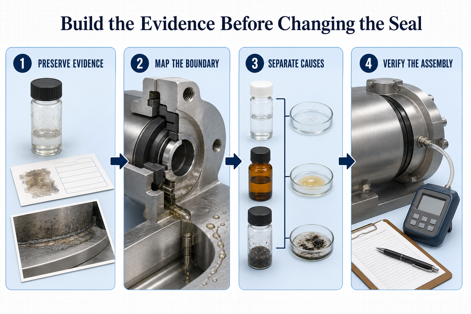
A staged investigation begins before cleaning or disassembly. Preserve the failed seal, residue or liquid sample where safe, photographs, component orientation and maintenance records. Record the observed symptom, timing, equipment state and any recent cleaning or replacement. Then inspect the seal, seat, groove, adjacent exhaust surfaces and drainage path. Compare used and unused or known-good components when available.
Keep chemistry, particles, oil or lubricant, compression and assembly evidence as separate streams. Visual residue inspection does not prove chemical incompatibility. Particle microscopy does not prove that the particle caused the leak. A material exposure test addresses response under selected conditions but not the assembled exhaust-side boundary. A leak test addresses the tested assembly and condition but cannot independently identify the mechanism.
Classify each result as observed, suspected, confirmed, inconclusive or not evaluated. Use a controlled exposure or motion test only when the test represents the relevant seal, fluid, interface and sequence. After maintenance, verify seating, alignment, cleaning, drainage and the assembled boundary under a defined condition. This sequence reduces the risk of selecting a new material when the actual cause is a drainage, exhaust-path or reassembly problem.
Design, Maintenance and Process Controls
Controls should match the mechanism being addressed. For condensate, review cold spots, low points, drainage, liquid traps, exhaust routing and process transitions. For chemistry, review compound and cleaning compatibility. For particles, review cleanliness, contact surfaces and particle-generation sources. For compression loss, review geometry, dwell, temperature and recovery evidence. For maintenance damage, review tools, handling, seating, alignment and post-service verification.
Maintenance records should link seal orientation, replacement status, exposure history, inspection observations, cleaning and drying, lubricant use and boundary-test results. A seal that looks acceptable may still contain residue, embedded particles, hidden distortion or recovery loss. Reuse decisions should follow equipment-specific acceptance criteria and evidence, not appearance alone. When the actual criteria are not supplied, the article can recommend a review but cannot assign an interval or pass/fail limit.
FMEA Risk Analysis: Condensate-Related Exhaust-Side Seal Concerns
The following qualitative FMEA is an engineering screening aid, not field statistics, a product rating or a confirmed failure analysis. It contains no assumed probability, severity, RPN, temperature, pressure, condensate volume, leak rate or service-life claim. Each row requires confirmation against the actual equipment and operating history.
Table 4. Qualitative FMEA for Condensate-Related Exhaust-Side Seal Concerns
| Failure Mode | Cause | Local Effect | System Effect | Detection Method | Control Action |
| Condensate retained at low point | Geometry, orientation or restricted drainage | Extended wetting near boundary | Residue or migration toward seal | Drainage and surface inspection | Review path and remove unjustified traps |
| Repeated wet-dry exposure | Temperature or process cycling | Residue or changing wetting | Cycle-dependent seal condition | Cycle record and residue review | Control transitions where justified |
| Cold surface beside seal | Thermal gradient or heat loss | Local condensation possibility | Exhaust-side retention | Temperature mapping | Evaluate thermal and drainage design |
| Reactive or incompatible condensate | Unconfirmed process or cleaner chemistry | Possible material change | Compression or friction shift | Composition and exposure review | Confirm chemistry and compound compatibility |
| Particle standoff at interface | Slurry, residue or maintenance debris | Local contact interruption | Leak sensitivity or wear | Interface microscopy | Improve cleanliness and verify assembly |
| Lubricant or oil film migration | Excess, incompatible or displaced lubricant | Changed wetting or friction | Contamination or boundary drift | Residue source analysis | Control lubricant selection and quantity |
| Compression loss after exposure | Dwell, thermal or chemical response | Reduced recovery | Lower contact pressure | Recovery and dimensional review | Set evidence-based condition criteria |
| Drainage path restriction | Residue, geometry or downstream obstruction | Liquid retention | System symptom misread as seal defect | Path and exhaust inspection | Correct verified restriction |
| Post-maintenance contamination | Incomplete cleaning or handling | Residue or particle at contact | Repeat leakage or contamination | Records and post-service inspection | Controlled cleaning and handling |
| Misalignment or uneven loading | Assembly, flatness or runout issue | Uneven contact | Localized wear or leakage | Alignment and compression review | Correct assembly or geometry |
| Exhaust restriction mistaken for seal failure | Downstream flow or pressure issue | No direct seal cause established | Incorrect replacement or redesign | Path and pressure-history review | Separate system and seal tests |
| Appearance-only diagnosis | No preserved evidence or separated tests | Wrong mechanism assigned | Repeated failure and wasted work | Failure-analysis review | Classify observation and uncertainty |
| Material test treated as system proof | Test boundary not stated | Overextended conclusion | Unverified service claim | Scope and limitation review | Link material and assembly evidence |
| Reuse of contaminated seal | Cost-driven reuse or weak criteria | Recurring local residue or damage | Repeat symptom | Inspection after cleaning | Define rejection and verification criteria |
| Unverified replacement interval | Generic practice applied to unknown service | Accumulation or premature change | Uncontrolled reliability drift | Trend and maintenance review | Set equipment-specific criteria |
Conclusion
Condensate buildup at a vacuum-pump exhaust-side seal is best investigated as a coupled boundary condition involving vapor, temperature, pressure history, surfaces, drainage and maintenance. Visible liquid or residue can be consistent with condensation, but it does not prove seal-material failure or identify the root cause of leakage. Chemical attack, particles, oil migration, compression loss, assembly damage and downstream exhaust problems may produce overlapping symptoms.
A defensible corrective action begins with the actual pump and exhaust configuration, fluid history, temperature and pressure information, seal details, drainage condition and maintenance evidence. Separate observation from inference, material-response testing from assembled-boundary verification, and a possible mechanism from a confirmed diagnosis. Only then should a team decide whether to review the seal material, the exhaust path, drainage, maintenance practice or the complete assembly.
FAQ
Q:Why can condensate collect near a vacuum pump exhaust-side seal?
A:Condensate may collect when a condensable vapor encounters a cooler surface or when liquid is retained by a low point, restricted path or drainage condition. Pressure history, flow path, surface temperature and vapor composition matter. The observation alone does not prove that the seal caused the accumulation.
Q:Does visible condensate prove that the seal material is incompatible?
A:No. Visible liquid or residue can result from condensation, cleaning material, process carryover, oil migration or another source. Chemical incompatibility requires chemistry and exposure evidence, such as a relevant material response under representative conditions.
Q:How can condensate buildup be separated from chemical attack?
A:Preserve the residue and seal before cleaning, document the location, review the fluid and cleaning history, and compare the seal with an unused component where possible. Controlled exposure can assess material response, but it must be interpreted separately from assembled leak performance.
Q:Can particles or oil residue worsen a condensate-related seal concern?
A:They can contribute to local standoff, friction change, contamination or particle transport, depending on the interface. Their presence does not establish causation. Particle location, morphology and residue source should be reviewed with seal and counterface evidence.
Q:What should be inspected before replacing the exhaust-side seal?
A:Record the original symptom first. Inspect the seal line, groove, seat, mating surface, nearby exhaust surfaces, low points, drainage path and maintenance condition. Review fluid history, cleaning, alignment, installation and available pressure or temperature records before assigning a root cause.
Q:How do temperature gradients and drainage affect condensate retention?
A:A cooler surface may make condensation more plausible, while a low point or restriction may allow liquid to remain or migrate. These are system-specific possibilities. Without actual temperature, composition, pressure and geometry data, no fixed dew point or condensate amount should be assumed.
Q:Which tests verify the assembled exhaust-side boundary?
A:A defined leak or boundary test can assess performance at its stated assembly and condition. It should be paired with visual, dimensional, residue, particle and material evidence when root cause matters. A single test state does not establish lifetime performance or identify the mechanism by itself.
Q:What should be recorded after maintenance or seal replacement?
A:Record the seal identity and orientation, cleaning and drying, lubricant use, seating and alignment observations, drainage condition, equipment state and the post-maintenance verification result. The exact acceptance criteria must come from the actual equipment or qualification plan.
Post time: Sep-12-2026