
Scope: This article addresses condensation caused by the interaction between ambient air and liquid cooling hardware. It does not replace the selected system design, equipment limits, or site commissioning procedure.
Executive Summary
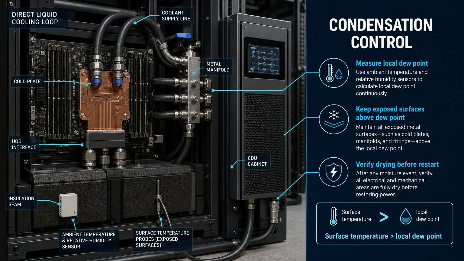
Condensation in a direct liquid cooling system is an environmental control problem, not simply a piping problem. Ambient temperature and relative humidity determine the local dew point. Any exposed surface whose temperature falls below that dew point can collect water, including cold plates, supply lines, quick-disconnect interfaces, metal manifolds, cabinet components and electrical connection areas.
The critical design comparison is the coldest exposed surface temperature versus the local air dew point. Coolant supply temperature is an important control variable, but it is not always equal to surface temperature: insulation, heat transfer, airflow, load state, fittings and thermal bridges create local differences. A fixed temperature margin may be useful, but it must be selected from sensor uncertainty, humidity variation, surface-temperature distribution and control response time.
Condensation must also be distinguished from coolant leakage. Condensation is passive deposition of atmospheric moisture on a cold surface; leakage is pressure-driven loss of loop fluid through a failed or open boundary. The two can occur at the same location and produce similar sensor signals, so diagnosis should use dew-point data, surface temperature, liquid properties, pressure, flow, level and location pattern together.
Dew Point Physics in Liquid Cooling Environments
Ambient temperature describes the air temperature at a measurement point. Relative humidity describes how close that air is to saturation at that temperature. Dew point temperature is the temperature at which the air would reach saturation if cooled at essentially constant moisture content. It therefore depends on both ambient temperature and relative humidity; ambient temperature alone cannot establish condensation risk.
For an illustrative calculation, at 25 °C ambient temperature, 60% relative humidity gives a dew point of approximately 16.7 °C, while 80% relative humidity gives a dew point of approximately 21.3 °C. These values are examples calculated for a stated air condition, not universal data-center limits. The relevant local value may be different inside a cabinet, near a rack, or close to an insulated penetration.
The condensation condition is:
Surface temperature < local dew point temperature
A useful engineering margin is the difference between the coldest exposed surface temperature and the local dew point. A 2–3 K margin is commonly cited as a design suggestion in cooling literature, but it is not a universal standard. The project margin should cover measurement uncertainty, spatial humidity variation, thermal bridges, control lag and the consequences of a wet electrical surface.
Table I: Temperature, Relative Humidity and Dew Point Risk Matrix
|
Ambient temperature |
Relative humidity |
Illustrative dew point |
Coolant supply temperature |
Illustrative margin |
Risk level |
| 25 °C | 40% | 10.5 °C | 18 °C | At least 7.5 K before local surface effects | Lower, if surfaces follow supply temperature |
| 25 °C | 60% | 16.7 °C | 18 °C | Approximately 1.3 K at supply reference | Conditional; verify coldest surface |
| 25 °C | 80% | 21.3 °C | 18 °C | Negative at supply reference | High condensation risk |
| 27 °C | 60% | 18.6 °C | 20 °C | Approximately 1.4 K at supply reference | Conditional; sensor and surface margin required |
| 27 °C | 75% | 22.2 °C | 20 °C | Negative at supply reference | High condensation risk |
This illustrative engineering example shows why coolant temperature cannot be assessed without local humidity. The final decision must use the lowest measured or calculated exposed surface temperature, not only the CDU setpoint or room dry-bulb temperature.
Condensation Risk at Critical Components
Different liquid cooling components have different condensation exposure because their surface temperature, thermal conductivity, exposed area, airflow and proximity to electrical hardware are different. The coldest exposed surface is often an uninsulated supply line, connector body or manifold rather than the loaded top surface of a cold plate.
Table II: Condensation Risk by Liquid Cooling Component
|
Component |
Surface temperature sensitivity |
Condensation exposure |
Electrical impact |
Monitoring and protection |
| Cold plate | Depends on load, coolant temperature and mounting path | High during low load or low supply temperature | Water can reach PCB or power zones | Surface sensor, controlled supply temperature, local barriers |
| PTFE pipe | Low thermal conductivity can slow surface response; fittings may be colder | Medium to high at exposed cold sections and bends | Indirect unless routed above electrical hardware | Surface checks, continuous insulation and protected routing |
| UQD interface | Metal body can approach coolant temperature quickly | High at exposed body and after connection work | Droplets can reach connectors and cable areas | Local surface sensor, removable insulation and visual inspection |
| Metal manifold | High conductivity and large exposed area | High, especially at supply branches and low airflow zones | Water can track toward rack electronics | Manifold surface sensors, insulation continuity and drain path |
| CDU cabinet | Internal cold components may see different air conditions | Medium to high at heat exchangers, valves and low points | Cabinet electrical assemblies may be nearby | Cabinet RH/dew point, surface sensors and separation |
| Insulation joint | Thermal bridge can create a local cold spot | High at seams, penetrations and damaged sections | Local wetting may be hidden | Joint inspection, surface sensing and sealed closures |
| Electrical connection area | Often warmer, but adjacent cold hardware can wet it | High consequence even with small water volume | Short circuit, corrosion and reduced insulation resistance | Keep cold surfaces away, condensation strip and electrical-safe alarm |
The table separates exposure from consequence. A component with moderate condensation probability can still require high-priority protection when it is close to energized electronics. Condensation detection and coolant leak detection should not be treated as interchangeable systems.
Monitoring, Insulation and Temperature Control
A robust control scheme combines ambient temperature and relative humidity sensing with dew-point calculation, surface-temperature measurement and equipment alarms. Ambient sensors should represent the air actually surrounding the cold hardware. A single room sensor may not represent cabinet interiors, rack corners, low points or areas affected by supply-air patterns.
Place sensors at the coldest expected locations: cold-plate inlet and outlet regions, supply and return lines, UQD interfaces, manifold surfaces, insulation seams and penetrations, CDU low points, cabinet bottoms and electrical areas adjacent to cold hardware. Surface-temperature sensors provide a direct margin measurement; condensation strips provide local physical evidence but have limited coverage and require inspection.
Table III: Dew Point Control and Monitoring Methods
|
Method |
Response speed |
Coverage |
Maintenance requirement |
Main limitation |
Best application |
| Ambient humidity control | Medium | Room or zone | Validate calibration and airflow | May miss local microclimates | Facility-level humidity management |
| Dew point sensor or calculated dew point | Fast to medium | Point or zone | Calibration and data validation | Does not measure surface temperature | Dynamic supply-temperature control |
| Surface temperature sensor | Fast | Specific surface | Attachment and calibration check | Limited to sensor location | Cold plates, manifolds and UQD bodies |
| Pipe insulation | Passive | Continuous if intact | Inspect seams, penetrations and damage | Does not control humidity or hidden bridges | Supply lines and exposed fittings |
| Local UQD insulation | Passive | Interface-specific | Remove and restore after maintenance | May obstruct inspection or operation | Connector bodies and service points |
| Coolant supply temperature control | Fast to medium | Loop-wide influence | Verify sensors, valves and control logic | Higher temperature may affect thermal performance | CDU and cold-plate operating envelope |
| Condensation detection strip | Fast at location | Local only | Replace or inspect after activation | Coverage and contamination limits | Low points and electrical-risk zones |
Insulation reduces heat transfer but does not eliminate condensation risk. Seams, penetrations, sensor attachments, UQD service areas and damaged or water-absorbed insulation remain thermal bridges. Temperature control, humidity management, sensing and post-maintenance restoration are required as one system.
Local airflow also changes the margin. A cold surface in a stagnant pocket can approach the coolant temperature, while a nearby supply-air stream may lower or raise the local dew point and surface temperature relative to the room average. During low-load operation or pump shutdown, thermal gradients can change faster than a room sensor responds. Control logic should therefore use validated local measurements, alarm on invalid or missing data, and treat an unmeasured cold surface as an uncertainty rather than as evidence of ion.&l>
Operating and maintenance sequence
FMEA Risk Analysis
Table IV: Condensation Risk FMEA and RPN Analysis
|
Failure mode |
Cause |
Local effect |
System effect |
Detection method |
Illustrative RPN |
Corrective action |
| Coolant surface below dew point | Low supply temperature or high local humidity | Water film or droplets | Electrical and corrosion risk | Dew point and surface-temperature margin | 168 | Raise supply temperature or reduce humidity; verify exposed surfaces |
| Damaged insulation | Tear, open seam or wet insulation | Thermal bridge and cold spot | Localized condensation | Visual and surface-temperature inspection | 144 | Repair, seal and verify after maintenance |
| Humidity sensor failure | Drift, contamination or communication loss | Dew point underestimated | Uncontrolled condensation exposure | Sensor plausibility and redundancy check | 180 | Fail safe, alarm and replace or calibrate |
| Surface temperature sensor failure | Poor attachment, drift or wiring fault | Margin overstated | Cold spot remains undetected | Cross-check with adjacent points | 160 | Alarm on invalid data and restore measurement |
| Condensation at UQD interface | Exposed metal below local dew point | Droplets near connection | Connector and cable corrosion risk | Local surface sensor and inspection | 150 | Restore local insulation and control temperature |
| Water accumulation near electrical components | Drainage path blocked or condensation unnoticed | Standing water | Short circuit or insulation degradation | Condensation strip and visual inspection | 192 | Isolate power, dry, inspect and improve drainage |
| False condensation alarm | Sensor contamination or leak-sensor cross-sensitivity | Unnecessary shutdown | Availability loss and alarm fatigue | Compare dew point, surface temperature and pressure trends | 126 | Tune logic and validate sensor condition |
| Restart before complete drying | Procedure bypass or unclear release criteria | Residual moisture remains | Electrical failure or corrosion | Restart checklist and insulation-resistance check | 180 | Require documented dry and electrically safe release |
The highest-priority controls are not limited to insulation. They include valid humidity and surface-temperature data, conservative alarm behavior, isolation of affected electrical equipment, documented drying, and a restart gate that distinguishes condensation from a continuing coolant leak. The control record should preserve the alarm sequence and operator release decision.
Conclusion
Condensation control in direct liquid cooling systems is governed by the thermal and moisture relationship between the local air and the coldest exposed hardware. Ambient temperature, relative humidity, dew point, coolant supply temperature and surface temperature must be evaluated together. The practical design variable is the surface-temperature margin above the local dew point, not ambient temperature alone.
Reliable control combines supply-temperature management, humidity control, insulation continuity, local surface monitoring, condensation evidence, alarm logic and maintenance discipline. No single measure eliminates condensation in every operating condition. Before restart, affected surfaces must be dry, electrical safety must be confirmed and a separate coolant leak must be excluded using pressure, flow, level and liquid-property evidence.
Engineering FAQ
Q:What is the difference between dew point risk and a liquid cooling leak?
A:Dew point risk is atmospheric moisture condensing on a surface below the local dew point. A liquid cooling leak is pressure-driven loss of coolant through a failed or open boundary. Use location pattern, liquid properties, pressure, flow, level, dew point and surface temperature together; water on a sensor is not proof of a leak.
Q:How much temperature margin should be maintained above the dew point?
A:A 2–3 K margin is a commonly cited engineering suggestion, not a universal requirement. The project margin should cover sensor uncertainty, local humidity variation, the coldest exposed surface, control response time and the consequence of water near energized equipment.
Q:Where should dew point and surface temperature sensors be installed?
A:Use representative ambient temperature and humidity points near the rack or cabinet, then add surface sensors at cold-plate inlet and outlet regions, supply lines, UQD interfaces, manifolds, insulation seams, CDU low points and electrical areas near cold hardware.
Q:Is pipe insulation alone sufficient to prevent condensation?
A:No. Insulation reduces heat transfer but cannot control humidity, protect every fitting or eliminate seams and penetrations. Supply temperature, local humidity, surface sensors, insulation inspection and maintenance restoration must operate together.
Q:What should operators do after a condensation alarm?
A:Follow the approved isolation sequence, protect or de-energize affected electrical equipment as required, identify the wet surface, check dew point and surface temperature, inspect insulation and rule out a coolant leak using pressure, flow and level data. Dry and inspect before restart.
Q:How should a liquid cooling system be verified before restart?
A:Confirm that affected surfaces and insulation are dry, the local surface-temperature margin is restored, sensors are valid, electrical safety checks are complete, drainage is clear and no continuing leak is indicated. Record the cause and corrective action before release.
Post time: Aug-17-2026