
Dynamic Check-Valve Seating in Reciprocating Pumps: Why High-Frequency Ball Impact Triggers Sealing Interface Breakdown
In positive-displacement diaphragm pumps, fluid transfer relies on the rapid cyclic opening and closing of suction and discharge ball check valves. Operating at 60 to 120 strokes per minute, a single valve ball undergoes millions of seating impacts within weeks. Each seating event is a dynamic collision driven by rapid fluid deceleration and steep differential pressure reversals across the chamber boundary.
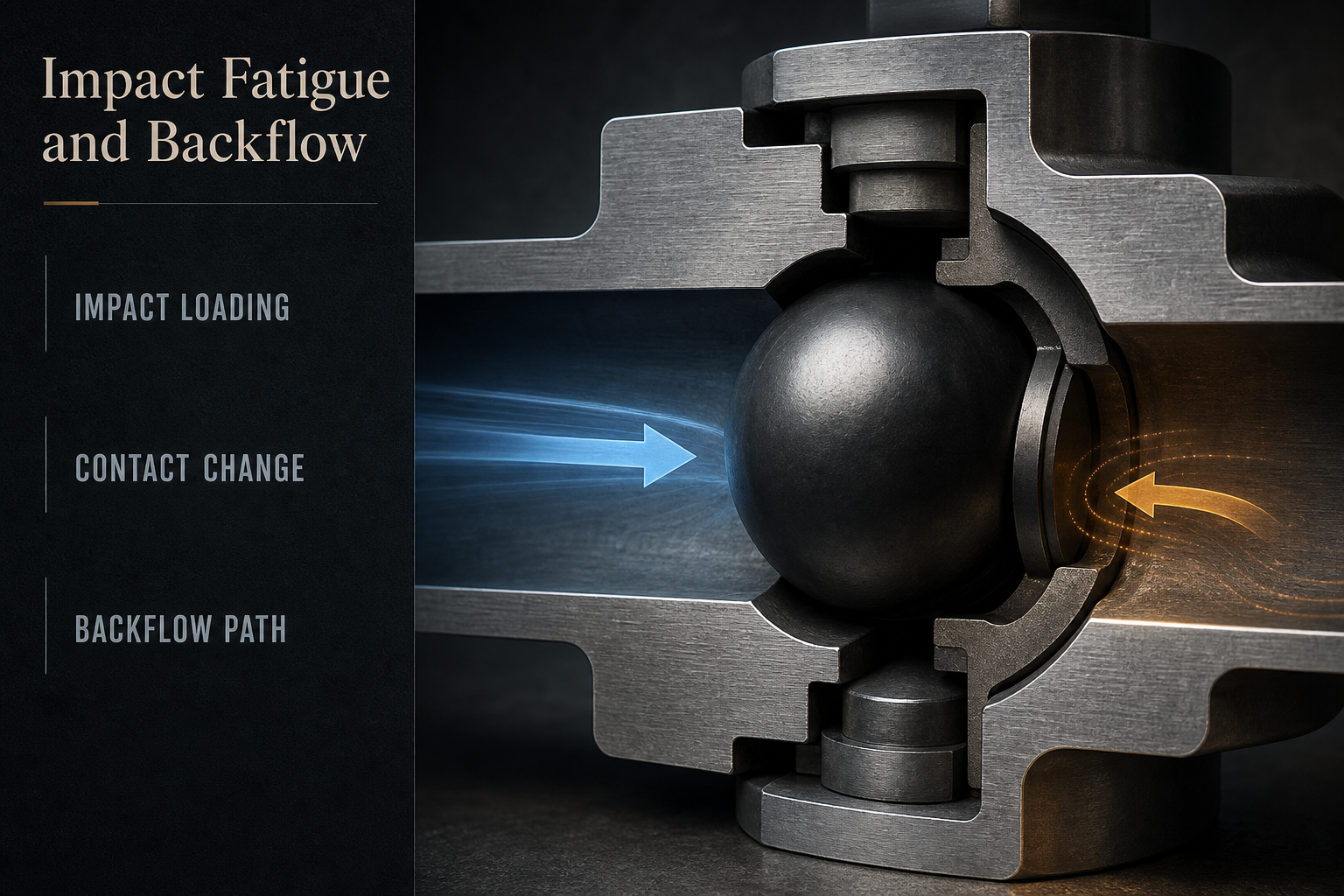
During stroke reversal, the ball accelerates toward the stationary seat driven by reverse flow drag, gravity, and fluid inertia. When striking the seat land, kinetic energy dissipates across a narrow annular contact line, generating localized compressive stresses far exceeding steady-state hydraulic pressures. Over extended cycling, repetitive impact induces micro-plastic deformation, surface fatigue cracking, and seat recession.
When seat geometry or ball sphericity degrades, the interface loses line-contact conformability. Sub-millimeter geometric mismatches introduce closing delays and asymmetric micro-gaps. Under discharge pressure, fluid escapes backward before complete closure, generating high-velocity reverse jetting. This transient backflow causes volumetric efficiency loss and accelerates cavitation erosion. Diagnosing coupled impact and backflow dynamics is essential for engineering durable check-valve boundaries.
Dynamic Ball-Valve Kinematics: Acceleration, Deceleration, and Impact Energy Distribution
Fluid Drag and Deceleration Forces During Stroke Reversal
As the diaphragm reverses from suction to discharge, the chamber pressure gradient inverts rapidly. Surrounding fluid reverses direction, exerting hydrodynamic drag that accelerates the ball toward its seat. Deceleration rates depend on liquid density, viscosity, stroke frequency, and guide cage geometry. In viscous slurries or high-pressure dosing duties, hydrodynamic drag accelerates the ball rapidly, amplifying touchdown collision energy.
Impact Kinetic Energy Dissipation Across the Sealing Land
Upon physical contact, translational kinetic energy dissipates through elastic and plastic deformation within the narrow contact band. Because initial contact between a rigid sphere and conical seat approaches a mathematical line contact, initial contact area is exceedingly small. Dynamic contact stresses spike to extreme localized peaks at touchdown before elastic compliance broadens the supporting band.
Micro-Mechanisms of Valve Seat Impact Fatigue and Surface Degradation
Cyclic Hertzian Contact Stress and Subsurface Micro-Cracking
Under repetitive impacts, localized stress fields beneath the seat contact line undergo cyclic shear reversals. In polymeric seats (PTFE, modified fluoropolymers, PEEK), cyclic shearing initiates subsurface micro-cracks propagating parallel to the seating surface. Over extended cycling, micro-cracks coalesce into surface spalling, micro-pitting, and delamination wear. In elastomeric seats (EPDM, FKM), dynamic compressive over-strain causes polymer chain scission, micro-tearing, and permanent indentation grooving.
Ball Sphericity Loss, Chatter Marks, and Asymmetric Seat Recession
When fluid turbulence or guide cage clearances induce valve ball wobble, eccentric impacts cause asymmetric yield across the seat ring. Concurrently, micro-slipping during touchdown produces circular chatter marks and fretting wear. As the seat land widens unevenly, unit contact pressure under static holding decreases, making the interface susceptible to low-pressure weeping.
Table 1 – Comparative Failure Modes in Diaphragm-Pump Ball Check-Valve Seating Interfaces
| Component / Material | Primary Stress Mode | Damage Morphology | Performance Drift | Operational Consequence | Engineering Control Action |
| Filled & Virgin PTFE Seats | Compressive yield and cyclic shear | Annular groove indentation, creep lip | Low-pressure weeping, delayed closing | Cavitation pitting along seat chamfer | Optimized chamfer radius and modified polymer compounding |
| Elastomer Seats (EPDM/FKM) | Dynamic impact fatigue, tensile tear | Radial micro-tearing, permanent grooving | Loss of suction lift, erratic metering | Chemical attack through micro-cracks | High-resilience peroxide-cured elastomer specification |
| Polymer Balls (PTFE/PEEK) | Asymmetric impact on cage and seat | Localized flats, ovality, scuffing | Intermittent valve hang-up, flow drift | Severe backflow during discharge stroke | Precision centerless grinding to tight sphericity |
| Metal & Ceramic Seats | Shock reflection and abrasive contact | Micro-chipping along seating edge | Immediate high-pressure back-leakage | Erosive cutting from reverse jet streams | Precision spherical lapping and travel restriction |
Hydrodynamic Backflow Mechanics and High-Velocity Interface Erosion
Transient Closing Lag and Reverse Fluid Jetting
Check-valve closure is never instantaneous. The finite time interval between stroke reversal and physical touchdown—valve closing lag—permits discharge fluid to slip backward into the pumping chamber. As the gap between descending ball and seat narrows to micrometers, differential pressure drives reverse fluid velocities exceeding 20 m/s. These fluid micro-jets generate localized shear forces that mechanically scour polymer and elastomer surfaces.
Cavitation Erosion and Acoustic Pressure Shock Waves
When high-velocity reverse fluid passes through micro-gaps into the lower-pressure chamber, static pressure drops below fluid vapor pressure, generating transient micro-bubbles. As vapor cavities travel into the collapsing boundary layer and implode against the seat face, they produce localized micro-jets and shock waves exceeding several hundred megapascals. This cavitation erosion carves wash-out channels across the seat face, turning minor backflow into severe valve failure.
Table 2 – Hydrodynamic Backflow Regimes and Interfacial Erosion Characteristics
| Backflow Operating Regime | Condition & Gap Scale | Fluid-Structure Mechanism | Interface Erosion Signature | Diagnostic Symptom | Recommended Valve Mitigation |
| Micro-Weeping Seepage | Closed ball, micro-gap < 5 μm | Capillary fluid penetration | Polished micro-channels | Discharge pressure decay at dwell | Precision seat finishing (Ra ≤ 0.4 μm) |
| Transient Closing Slip | Closing lag, gap 50 μm to zero | High-velocity reverse jetting | Smooth wash-out grooves | Volumetric efficiency drop | Reduced ball travel stroke height |
| Cavitation Jet Erosion | High pressure drop (> 0.6 MPa) | Local vapor bubble collapse | Deep sponge-like micro-pitting | Acoustic chatter, discharge pulse | Contoured anti-cavitation seat entries |
| Solid Particle Entrapment | Particulate slurry in closing gap | Point-contact stress concentration | Circular dents, embedded cutting | Loss of prime, continuous backflow | Chamfered self-clearing seat angles (45°) |
Material Compatibility, Thermal Softening, and Particulate Pinching Dynamics
Elastomer Swelling and Chemical Softening Under Dynamic Impact
Process fluid chemistry profoundly alters check-valve component resilience. Absorption of aggressive chemicals, solvents, or cleaning agents causes elastomer plasticization, swelling, and tensile modulus decay. A softened seat undergoes excessive dynamic deformation under impact, spreading the contact band and increasing adhesion forces delaying valve release on the subsequent suction stroke. Conversely, chemical embrittlement causes premature micro-cracking and catastrophic seat fracture under low-energy impacts.
Particulate Slurry Pinching and Three-Body Abrasion
In slurry and wastewater transfer duties, solid particles suspended in fluid become trapped between descending ball and seat land. When the ball seats on abrasive mineral grains, closing loads concentrate onto minute contact areas, creating localized stresses exceeding polymer compressive yield strength. This three-body abrasive interaction embeds hard particles into polymer seats, gouging circular sealing tracks and preventing liquid-tight seating.
Table 3 – Chemical and Particulate Compatibility Matrix for Diaphragm-Pump Ball Valve Materials
| Valve Pairing | Chemical Resistance & Temp Profile | Slurry Resilience | Impact Resistance (Max Temp) | Primary Vulnerability | Recommended Target Duty |
| PTFE Ball / PTFE Seat | Universal chemical inertness (pH 0–14) | Low; abrasive grains embed | Creep softening above 80°C | Cold-flow indentation under high heads | Pure chemical dosing, aggressive fluids |
| EPDM Ball / EPDM Seat | Resistance to polar solvents, steam, acids | High resilience; absorbs shock | Stable to 130°C (peroxide cured) | Swelling in petroleum oils and fuels | Water treatment, wastewater, mild chemical |
| FKM Ball / FKM Seat | Resistance to hydrocarbons, fuels, acids | Moderate slurry tear resistance | Stable up to 180°C | Swelling in polar solvents and ketones | Petrochemical, solvent transfer, hot oils |
| Stainless / PEEK Seat | Broad chemical resistance across pH | Exceptional slurry erosion resistance | High modulus up to 200°C | Rigid boundary requires high sphericity | High-pressure slurry injection, mining |
Yokey Engineering Controls: Valve-Seat Geometry Matching, Precision Sphericity, and Impact Attenuation
Precision Spherical Radius Matching and Chamfer Optimization
To eliminate stress concentrations and reduce dynamic impact forces, Yokey engineers check-valve sealing interfaces with optimized spherical and conical land geometries. By matching seat chamfer angles (45° to 60°) to dynamic ball approach vectors, Yokey seat profiles maximize initial elastic contact area upon touchdown. Generous blend radii (R ≥ 0.8 mm) along entry and exit edges eliminate acute knife-edge transitions, preventing fluid turbulence, edge chipping, and localized cavitation initiation.
Controlled Compression and Anti-Extrusion Backup Architecture
In high-pressure diaphragm pumping applications, elastomeric valve seats require robust mechanical retention to prevent displacement and extrusion during cyclic loading. Yokey incorporates precision-machined metallic or PEEK back-up support rings that constrain the elastomer within defined compression limits (15% to 22%). This structural reinforcement prevents excessive bulk deformation under high discharge pressures while ensuring rapid elastic recovery during suction release.
High-Purity Material Compounding and Precision Machining
Yokey manufactures check-valve components utilizing certified virgin and modified compounds—including peroxide-cured EPDM, premium-grade FKM, and carbon-reinforced PTFE. All valve seats undergo precision multi-axis CNC turn-mill machining, maintaining strict dimensional tolerances (ISO H7/f7) and mirror surface micro-finishing (Ra ≤ 0.4 μm). Valve balls are finished through centerless spherical grinding to achieve strict sphericity tolerances (Grade 25 to Grade 100), eliminating out-of-round wobble and ensuring concentric seating on every pump cycle.
Application-Specific Engineering Review: The Yokey 4-Step Ball-Seat Evaluation Workflow (CTA)
When industrial diaphragm pumps experience recurring loss of prime, erratic dosing, high-frequency valve rattle, or premature seat erosion, standard replacement parts cannot solve underlying fluid-structure dynamic mismatches. Plant operators and pump OEMs can initiate a structured technical review through the Yokey 4-Step Ball-Seat Interface Engineering Evaluation:
1. Operating Envelope Characterization: Submit pumping parameters including stroke rate (SPM), pressure profiles, fluid viscosity, particle size, and temperature.
2. Transient Dynamic Simulation: Calculate ball kinetic energy, closing deceleration rates, and reverse slip velocities to model impact severity.
3. Seat Geometry Matching: Configure seat chamfer angles, elastomeric compliance, or PEEK anti-extrusion back-up structures to dissipate shock.
4. Polymer Compound Verification: Specify high-tear-resistance elastomers or modified fluoropolymers ensuring chemical compatibility and fatigue resistance.
FMEA Risk Matrix: Failure Mode and Effects Analysis for Diaphragm-Pump Ball Valve Sealing
Table 4 – Failure Mode and Effects Analysis (FMEA) for Diaphragm-Pump Ball Valve Interfaces
| Failure Mode | Direct Failure Cause | Local Interface Effect | System-Level Effect | Detection Method | Engineering Control Action |
| Seat Impact Chipping | High-velocity ball impact (> 100 SPM) | Micro-cracks propagate along seat edge | Back-leakage, loss of prime, head drop | Acoustic vibration and borescope | Upgrade to Yokey optimized chamfer seats |
| Elastomer Seat Extrusion | Hydraulic pressure exceeding tear modulus | Elastomer flows into guide clearance | Closing delay, erratic dosing, hang-up | Displacement deviation and teardown | Install Yokey PEEK backup support rings |
| Reverse Jetting Cavitation | Delayed valve seating, reverse micro-gap | Erosion trenches carved into seat face | Efficiency collapse, high valve rattle | Pressure decay and ultrasonic test | Implement Yokey reduced-travel ball cages |
| Slurry Particle Pinching | Abrasive solids trapped during touchdown | Circular indentations, embedded grains | Continuous weeping, loss of prime | Flow meter check and swab analysis | Specify Yokey dual-durometer 45° seats |
| Chemical Swelling Softening | Incompatible process fluid absorption | Volume swell, modulus decay, sticking | Suction stall, pump cavitation | Shore hardness test and fluid log | Configure Yokey peroxide EPDM or FKM |
| Ball Sphericity Loss | Unguided collision against cage ribs | Impact flats, out-of-round ovality | Valve hang-up, volume inconsistency | Micrometer roundness inspection | Deploy Yokey centerless ground balls |
Physical Validation Path: 5-Stage Protocol for Check-Valve Seating Integrity
To establish rigorous engineering verification for ball check-valve seating performance, Yokey recommends a structured 5-stage validation protocol:
Stage 1 – Dimensional Metrology and Sphericity Profiling: Verify valve ball sphericity tolerances (Grade 25 to 100) using 3D CMM and optical roundness profilometers. Inspect valve seat chamfer angles (45° ± 0.5°), blend radii, and surface roughness (Ra ≤ 0.4 μm) using stylus profilometry to confirm stress riser elimination.
Stage 2 – Dynamic Impact Cyclic Fatigue Simulation: Subject ball and seat assemblies to high-frequency pneumatic impact testing (> 150 SPM) under dry and lubricated conditions for 1,000,000 cycles. Measure indentation depth, seat land widening, and micro-cracking using SEM microscopy.
Stage 3 – Static and Dynamic Backflow Decay Testing: Install valve assemblies in calibrated fixtures under static hydraulic back-pressure from 0.05 MPa to 1.6 MPa. Measure reverse leakage rates across holding durations using mass-flow sensors to verify zero-leakage sealing performance.
Stage 4 – Chemical and Thermal Exposure Resilience Profiling: Submerge elastomeric and polymer seat samples in aggressive chemical baths at elevated operating temperatures (80°C to 150°C) for 168 hours. Quantify volume swell percentage, tensile strength retention, and hardness drift.
Stage 5 – Full-Scale Pump Operating Efficiency and Dosing Validation: Install validated valve components into complete production diaphragm pumps. Execute continuous pumping trials under maximum discharge pressure and high stroke frequency for 500 hours, monitoring efficiency and acoustic stability.
Comprehensive Engineering Synthesis: Maintaining Hydraulic Integrity in Reciprocating Valve Boundaries
The operational reliability and volumetric precision of reciprocating diaphragm pumps depend fundamentally on the physical integrity of their check-valve sealing boundaries. A check valve is not a passive mechanical component; it is a dynamic interface enduring millions of high-velocity impacts, cyclic contact stress reversals, and transient fluid shear stresses throughout its service life.
Addressing check-valve degradation requires moving beyond repetitive part replacement toward rigorous engineering diagnosis. Premature failure—whether manifested as seat impact fatigue, cavitation wash-out, particulate embedding, or chemical softening—stems from identifiable mismatches between fluid-structure dynamics, component geometry, and material mechanical properties.
By implementing optimized seat chamfer angles, controlled-compression backup glands, high-sphericity precision valve balls, and application-matched polymer formulations, industrial pump operations can effectively eliminate reverse slip flow, prevent cavitation erosion, and stabilize volumetric dosing efficiency. Establishing structured FMEA risk controls and executing multi-stage physical validation ensures that reciprocating pump systems achieve predictable, long-term fluid handling reliability across severe chemical, slurry, and high-pressure industrial duties.
Frequently Asked Questions (FAQ)
Q: What is the primary physical cause of check-valve closing lag in high-speed diaphragm pumps?
A: Valve closing lag is primarily caused by fluid inertia, viscous drag opposing ball motion, and excessive ball travel height within the guide cage. At high stroke frequencies (> 90 SPM), fluid reverses direction before the ball can traverse the travel gap and seat, resulting in transient backflow and reduced volumetric efficiency.
Q: How does valve seat chamfer angle affect contact stress and impact fatigue resistance?
A: A steeper seat chamfer angle (45° to 60°) increases initial geometric contact area upon touchdown, distributing kinetic energy over a broader land and lowering peak Hertzian compressive stresses. Steeper angles also promote self-centering and improve particulate shedding compared to flat or narrow-radius seat pockets.
Q: Why do PTFE valve seats often experience low-pressure weeping after extended operation?
A: PTFE is subject to cyclic compressive creep (cold flow) under repetitive ball impact. Over millions of cycles, the seat land permanently deforms and widens, reducing localized unit contact stress under low differential pressures. Without sufficient sealing contact pressure, process fluid seeps across the widened interface until high pressure forces conformability.
Q: What is the difference between mechanical wear and cavitation erosion on a valve seat?
A: Mechanical wear produces smooth, polished, or burnished annular grooves aligned with the circular ball contact line. Cavitation erosion creates irregular, rough, sponge-like micro-craters and deep jagged wash-out channels, typically located on the downstream edge of the seat where high-velocity reverse fluid micro-jets implode.
Q: How do abrasive slurry particulates accelerate ball-valve sealing degradation?
A: When solid particles are pinched between ball and seat during closure, the closing load concentrates on microscopic points, exceeding polymer yield strength. This causes three-body abrasive cutting, embeds abrasive grains into the seat face, and props the ball open, leading to continuous high-velocity backflow wash-out.
Q: When should spring-assisted check valves be considered instead of free-floating gravity balls?
A: Spring-assisted check valves should be deployed in high-viscosity fluid duties (> 500 cP), high stroke frequency applications, or horizontal pump mounting orientations where gravitational and fluid drag forces are insufficient to seat the ball rapidly, eliminating severe closing lag and backflow.
Q: What role does valve ball sphericity play in preventing check-valve chatter and backflow?
A: High-precision sphericity (Grade 25 to 50) ensures that the valve ball presents an identical geometric curvature to the seat regardless of rotational orientation. Out-of-round or scuffed balls seat eccentrically, creating transient crescent-shaped micro-gaps that leak and induce lateral ball wobble during stroke transitions.
Q: When should plant engineers submit pump operating data for a Yokey ball-seat engineering evaluation?
A: Plant engineers should submit operating dossiers whenever diaphragm pumps exhibit recurring loss of suction prime, volumetric flow drift exceeding 5%, persistent valve rattle, premature seat cracking within 6 months, or when upgrading pump duties to aggressive chemical slurries requiring customized sealing geometry review.
Post time: Oct-12-2026