
Executive Summary
Diaphragm valves in semiconductor wet-process equipment perform more than on-off flow control. They isolate the actuator from the chemical, protect cleanliness, limit retained fluid and help prevent cross-contamination between process steps. Their long-term reliability depends on diaphragm fatigue, chemical exposure, pressure cycling, actuation frequency, dead volume, particle generation, extractables, seat condition and assembly quality.
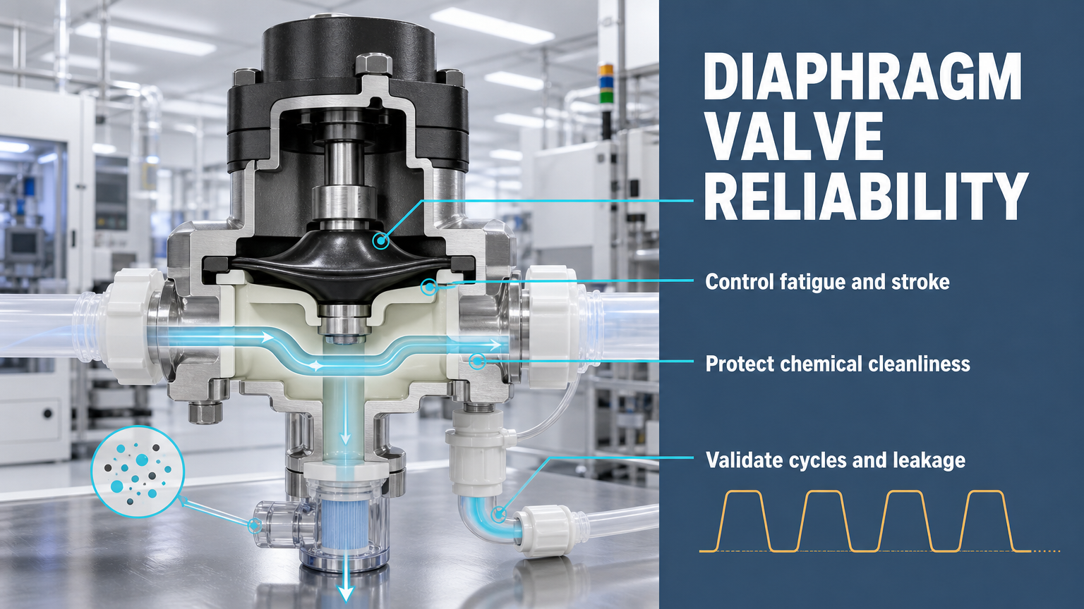
A diaphragm forms the flexible process boundary while the actuator applies a controlled stroke to open or close the valve seat. Repeated flexing can create thinning, crack initiation or rupture, while chemical exposure can change swelling, stiffness, permeability or fatigue behavior. A valve that remains mechanically functional may still be unsuitable if it releases particles, retains chemical residue or produces unacceptable extractables.
Reliable selection therefore combines material, diaphragm geometry, clamping, seat design, flow path, cleaning, packaging, maintenance and validation. PTFE, PFA, EPDM, FKM, FFKM and composite structures can each be appropriate in defined conditions; no single material is universal.
Diaphragm Valve Operating Principle
A diaphragm valve uses a flexible diaphragm between the actuator and the process fluid. The actuator converts a stroke into diaphragm deflection and closing force; the diaphragm then contacts the valve seat or lifts away from it. Under normal operation, the process chemical should not contact the actuator or a conventional moving stem boundary.
The diaphragm is therefore both a dynamic mechanical element and a process-fluid boundary. Its stroke, bending radius, clamping region and support geometry determine local strain. The valve body and seat determine dead volume, drainability and the amount of chemical that can remain after closing, rinsing or drying.
The reliability chain is: actuator command -> diaphragm deflection -> seat contact -> process isolation or flow -> pressure and chemical exposure -> elastic recovery during the next cycle. A design that controls only closing force but not stroke, clamping stress or retained fluid is incomplete.
Diaphragm Fatigue and Mechanical Failure
Diaphragm fatigue is driven by repeated flexing and the strain imposed by each stroke. Higher actuation frequency increases cycle accumulation, while excessive stroke increases bending strain. Pressure differential adds membrane loading, and sharp transitions or uneven clamping can concentrate stress at the diaphragm edge.
Chemical exposure and temperature cycling can change material stiffness and recovery. A hardened diaphragm may no longer conform as intended; a softened diaphragm may deform excessively; a chemically damaged surface may initiate cracks under a previously acceptable stroke. Failure analysis should distinguish thinning, crack initiation, crack propagation, pinhole leakage, full rupture and clamp-edge damage.
The actuator setting is part of the fatigue design. Over-travel, incorrect calibration, excessive closing force and misalignment can reduce life even when the diaphragm material is chemically suitable. Cycle testing should therefore use the actual stroke, pressure, temperature and chemical condition rather than a generic motion profile.
Chemical Compatibility and Material Selection
PTFE and PFA diaphragms may be considered for selected aggressive chemical environments, while EPDM, FKM and FFKM may be considered in other defined process conditions. Composite or reinforced structures can add mechanical support, but the interface between layers becomes part of the qualification problem.
Material selection must account for acid, base, oxidizer, solvent, concentration, temperature, pressure, exposure duration, cleaning and rinsing. Chemical swelling, permeation, extractables, mechanical fatigue, stress cracking and particle shedding are separate mechanisms. A material may resist chemical attack but still fail through fatigue, release unacceptable extractables or generate particles after repeated flexing.
The selected compound or laminate must be tested in the actual chemical formulation and construction. Family names alone do not establish compatibility. A wet-process valve also requires cleanliness evidence for processing, packaging, assembly and maintenance, not only a material data sheet.
Cleanliness, Dead Volume and Contamination Control
Low dead volume is important because retained chemical can remain after the valve closes and can be released into a later process step. Diaphragm folds, seat transitions, clamp regions, body joints and poorly drained pockets should be assessed for residual liquid. Drainability, rinse access and drying behavior are part of valve design.
Cleanliness is a process property. Material formulation, machining, cleaning, drying, packaging, transport, tools and operator handling can all introduce particles or extractables. A clean material can become a contamination source if it is damaged during assembly or exposed to an uncontrolled work area. Maintenance should use capped connections, traceable parts, controlled rinsing and documented drying.
Particle and extractables testing should define the chemical, rinse method, sample volume, detection method and acceptance criterion. The result should be separated from pressure and leakage results because a valve can pass a pressure test while failing a cleanliness requirement.
Valve Design and Maintenance
Design variables include diaphragm clamping, seat geometry, internal surface finish, actuator stroke control, pressure equalization, drain and flush paths, service access and part traceability. The clamp should avoid sharp stress concentration and maintain repeatable support. The seat should close without unnecessary over-travel or local damage.
During maintenance, inspect the diaphragm for permanent deformation, thinning, cracks and chemical staining. Inspect the seat and body for scratches, particles and retained liquid. Confirm actuator stroke and position after replacement, then perform pressure, leakage and cleanliness verification before release. A replacement procedure should define orientation, torque sequence, rinsing, drying and records.
Table I: Diaphragm Material and Application Comparison
|
Material or structure |
Potential strength |
Mechanical fatigue tendency |
Extractables or particle concern |
Suitable application |
Main limitation |
| PTFE diaphragm | Broad chemical resistance in selected uses | Flexing and creep must be evaluated | Processing and particle control required | Selected wet-process chemicals | Cold-flow and support sensitivity |
| PFA diaphragm | High-purity fluoropolymer option in selected designs | Geometry and laminate construction matter | Requires process and cleaning validation | Chemical delivery and clean paths | Construction and temperature boundary |
| EPDM diaphragm | Selected aqueous and alkaline service | Temperature and chemistry dependent | Compound and processing dependent | Defined water-based systems | Not universal for oxidizers or solvents |
| FKM diaphragm | Selected chemical and temperature conditions | Compound and exposure dependent | Must be validated for process chemistry | Specific chemical-delivery envelopes | Grade-specific compatibility |
| FFKM diaphragm | Selected severe chemical or high-consequence conditions | Cost and structure remain relevant | Requires compound and cleanliness validation | High-consequence process systems | High cost and design sensitivity |
| Composite or reinforced diaphragm | Combines support and flexible sealing | Interface and laminate stress require testing | Construction-dependent | Pressure or stroke-sensitive designs | More complex qualification |
The selection is condition-dependent. Chemical concentration, temperature, pressure, stroke, frequency, exposure duration, cleaning method and cleanliness requirements must be stated before comparing diaphragm materials.
Table II: Factors Affecting Diaphragm Fatigue Life
|
Factor |
Local mechanism |
Likely failure mode |
Detection method |
Recommended control |
| Actuation frequency | More cycles per unit time | Fatigue accumulation | Cycle counter and leakage trend | Define duty cycle and inspection interval |
| Diaphragm stroke | Higher bending strain | Thinning or crack initiation | Stroke measurement and teardown | Limit stroke and calibrate actuator |
| Pressure differential | Higher membrane loading | Fatigue or rupture | Pressure-cycle test | Define pressure envelope |
| Temperature | Material softening, hardening or expansion | Recovery loss or cracking | Thermal-cycle and exposure test | Validate temperature condition |
| Chemical exposure | Swelling, permeation or stress cracking | Chemical degradation | Exposure and post-test inspection | Test actual chemical formulation |
| Clamping stress | Local stress concentration | Clamp-edge crack | Geometry review and teardown | Control clamp design and load |
| Valve-seat geometry | Uneven contact or over-travel | Local stress or leakage | Seat inspection and stroke test | Control seat and actuator setup |
| Material thickness | Changed strain and flexibility | Fatigue or incomplete closure | Dimensional inspection and cycle test | Control construction tolerance |
Fatigue life is governed by the interaction of stroke, pressure, temperature, chemistry, clamping and construction. A material comparison without these variables cannot predict service life.
Testing and Validation
A complete validation plan combines mechanical, pressure, chemical and cleanliness evidence. Actuation-cycle and fatigue tests assess repeated flexing. Pressure-hold, seat-leakage and external-leakage tests assess different boundaries. Chemical exposure tests should state concentration, temperature, pressure, duration and sample construction.
Extractables, particle, rinse and cleanliness verification should define the sampling method, detection limit and acceptance criterion. Post-test teardown should inspect thinning, cracks, stress cracking, swelling, residue, particles and seat damage. Test records should include diaphragm material, valve type, chemical medium, concentration, temperature, pressure, differential pressure, frequency, stroke, cycle count, leakage and particle or extractables result.
Table III: Cleanliness and Diaphragm Valve Validation Matrix
|
Test |
Test objective |
Key parameter |
Detectable failure |
Main limitation |
Suitable stage |
| Actuation cycle test | Assess repeated flexing | Stroke, frequency and cycles | Friction rise, leakage or stroke change | Does not represent every chemical condition | Design validation |
| Pressure hold test | Verify pressure boundary | Pressure and duration | Pressure decay or wetting | Does not prove cleanliness | Assembly and service release |
| Seat leakage test | Verify closed-valve isolation | Pressure, direction and temperature | Internal leakage | Cannot prove diaphragm life | Design and acceptance |
| Chemical exposure test | Assess material response | Chemical, concentration, temperature and time | Swelling, cracking or stress damage | Requires representative construction | Material qualification |
| Extractables test | Assess released species | Fluid, sampling and detection method | Chemical release | Method and detection-limit dependent | Process qualification |
| Particle test | Assess particle generation | Rinse, sample and count method | Particle shedding | Requires controlled sampling | Cleanliness qualification |
| Rinse and cleanliness verification | Assess residual chemical and contamination | Rinse condition and acceptance | Carryover or residue | Must represent actual cleaning process | Maintenance and release |
| Post-test teardown | Identify physical mechanism | Visual and analytical inspection | Thinning, cracks, residue or damage | Destructive | Root-cause analysis |
No single test proves diaphragm-valve reliability. Mechanical cycling, pressure, chemical exposure, particles, extractables, rinsing and teardown provide different evidence and should be linked to the intended process condition.
FMEA Risk Analysis
A diaphragm-valve FMEA should distinguish mechanical fatigue, chemical degradation, cleanliness failure, geometry error and maintenance error. Typical modes include diaphragm fatigue, rupture, swelling, stress cracking, thinning, seat damage, particle shedding, dead-volume contamination, stroke error, excessive pressure differential, incomplete cleaning and incorrect diaphragm replacement.
RPN is a prioritization aid, not a universal safety limit. The values below are illustrative engineering assessments; project scoring must define Severity, Occurrence and Detection and convert high-priority items into design, test and maintenance controls.
Table IV: Diaphragm Valve FMEA and RPN Analysis
|
Failure mode |
Cause |
Local effect |
System effect |
Detection method |
Illustrative RPN |
Corrective action |
| Diaphragm fatigue | Repeated flexing or excessive stroke | Thinning or crack initiation | Leakage or process interruption | Cycle test and teardown | 170 | Control stroke and duty cycle |
| Diaphragm rupture | Pressure pulse, fatigue or damage | Loss of process boundary | Chemical release or equipment shutdown | Pressure and leakage test | 190 | Define pressure and replacement limits |
| Chemical swelling | Incompatible chemistry or concentration | Geometry and contact change | Leakage or contamination | Exposure and dimensional test | 175 | Validate material and fluid |
| Stress cracking | Chemical exposure and local strain | Crack growth | Leakage or particle risk | Exposure and visual inspection | 180 | Reduce stress and requalify construction |
| Valve seat damage | Particles, over-travel or wear | Incomplete closure | Chemical flow error or leakage | Seat inspection and leakage test | 160 | Protect seat and calibrate stroke |
| Particle shedding | Material wear or poor cleaning | Particles enter process fluid | Yield or contamination risk | Particle test and inspection | 185 | Control material, process and cleaning |
| Dead-volume contamination | Poor drainability or retained chemical | Residual fluid remains | Cross-contamination | Rinse and cleanliness verification | 175 | Redesign flow path and flush process |
| Incorrect actuator stroke | Calibration or setup error | Over-travel or incomplete closure | Leakage or fatigue acceleration | Stroke and position test | 155 | Calibrate actuator and verify |
| Incomplete cleaning | Insufficient rinse, dry or handling control | Residue and extractables | Chemical contamination | Cleaning record and extractables test | 180 | Qualify cleaning and release gate |
| Incorrect diaphragm replacement | Wrong part, orientation or clamp load | Immediate local defect | Repeat failure or outage | Part, assembly and pressure test | 190 | Traceable replacement procedure |
All RPN values are illustrative engineering assessments, not universal safety limits, certification results or field-failure statistics.
Conclusion
Semiconductor wet-process diaphragm-valve reliability is not a single-material problem. It combines diaphragm material, geometry, actuation stroke, pressure cycling, chemical exposure, seat design, dead volume, clean assembly, testing and maintenance.
A reliable solution should provide chemical resistance, fatigue resistance, low dead volume, low particle generation, low extractables, stable shut-off and repeatable actuation. These requirements must be demonstrated under the actual chemical concentration, temperature, pressure, stroke, frequency and cleaning process.
Engineering FAQ
Q:Why are diaphragm valves used in semiconductor chemical delivery systems?
A:A diaphragm can isolate the actuator from the process fluid while providing controlled closure and a low-retention flow path. The valve still requires validation of fatigue, chemical exposure, cleanliness, pressure and seat performance.
Q:What causes diaphragm fatigue in wet-process valves?
A:Repeated flexing, excessive stroke, pressure cycling, clamping stress, thermal cycling, chemical degradation and actuator misalignment can combine to create thinning, crack initiation or rupture.
Q:How should PTFE, PFA, EPDM, FKM and FFKM diaphragms be compared?
A:Compare the specific construction against chemical concentration, temperature, pressure, stroke, frequency, exposure time, extractables, particles, cleaning and maintenance requirements. Material family names alone are insufficient.
Q:Why is low dead volume important in semiconductor chemical valves?
A:Low dead volume reduces retained chemical, rinse demand and cross-contamination risk. Geometry, drainability, diaphragm folds, seat transitions and cleaning flow affect retained volume.
Q:Which tests are necessary to verify diaphragm valve cleanliness and reliability?
A:Use cycle, pressure, seat leakage, chemical exposure, extractables, particle, rinse and cleanliness tests, followed by teardown where appropriate. Each test should state its chemical and measurement conditions.
Q:How can diaphragm failure be detected before chemical leakage occurs?
A:Track stroke, actuation force, leakage, pressure behavior, cycle count and cleanliness indicators. Rising friction, stroke change, pressure instability or particles can justify inspection before visible rupture.
Post time: Aug-20-2026