
Executive Summary
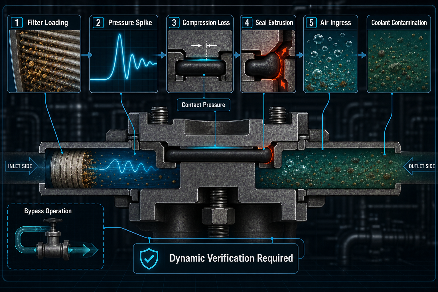
A CDU filter-housing seal is not exposed to one static pressure value. It works at an interface where filter resistance, flow demand, pump transients, temperature and maintenance repeatedly change the local load. Filter loading can increase differential pressure, but high differential pressure alone does not prove seal failure. The critical question is how pressure amplitude, rise rate, cycle frequency, temperature and housing deformation change seal compression and contact pressure.
Differential-pressure cycling can expose insufficient squeeze, uneven compression, extrusion, seal slip, rolling and fatigue more clearly than a static pressure-hold test. Cartridge resistance, housing stiffness, cover preload and groove geometry jointly define the actual sealing state. Evaluation must address liquid leakage, air ingress, contamination, bypass abnormality and resealing. CDU filter-housing sealing should be evaluated as a cyclic pressure-interface system rather than as a static gasket under one nominal pressure.
CDU Filter-Housing Architecture and Pressure Boundaries
A liquid-cooling CDU filter assembly includes the filter housing, cover, cartridge, basket, inlet, outlet, upstream and downstream sides, pressure ports, O-ring groove, flat gasket, end-face seal, clamp or bolted cover, drain port, vent port, bypass valve and housing wall. Upstream pressure rises as the cartridge accumulates particles, while downstream pressure depends on pump demand, loop restriction and flow distribution. The difference between these points is not the same as the local pressure at every seal surface.
The cover seal protects the housing boundary, the cartridge-end seal separates filtered and unfiltered flow, and drain, vent and sensor interfaces create smaller but independent leakage paths. A bypass valve can reduce the cartridge pressure drop or preserve flow when resistance increases, yet it also changes the pressure distribution and adds its own sealing boundary. Air bubbles, venting events and drain-port residue can produce local paths that do not appear in a simple housing pressure check.
Wall thickness, cover stiffness, bolt spacing, clamp geometry and flange flatness determine whether compression remains continuous. Cartridge support can also transfer reaction load into the cover. The design should therefore separate upstream pressure boundary, downstream pressure boundary, cover sealing boundary, cartridge sealing boundary, drain and vent boundary, and bypass-flow boundary before assigning verification methods.
Table I: CDU Filter-Housing Pressure Boundaries and Seal Functions
| Boundary | Pressure exposure | Seal function | Typical risk | Verification | Limitation |
| Cover seal | Housing pressure | Block leak | Low compression | Leak test | Not cartridge proof |
| Cartridge seal | Filter drop | Separate flow | Bypass leak | Flow check | Hidden path |
| Drain or vent | Service pressure | Close port | Residue leak | Local check | Maintenance driven |
| Pressure port | Sensor pressure | Measure DP | False signal | Sensor audit | Location sensitive |
| Bypass seal | Bypass flow | Control path | Unwanted bypass | Valve test | Separate boundary |
Sources of Differential Pressure and Pressure-Cycle Formation
Differential pressure begins with resistance. Particle accumulation increases cartridge resistance, but the pressure response is not a simple straight line because flow rate, pump-speed control, coolant viscosity, local blockage and parallel-loop imbalance all interact. A cold start may raise viscosity and resistance before the system reaches its normal thermal state. High-flow operation can push a partially loaded filter into a sharper pressure response than the same cartridge would show at lower flow.
Pump start-up, shut-down, valve switching and flow redistribution can create pulsation or water-hammer-like transients. A gas pocket entering the filter housing can reduce effective flow area, alter sensor readings and collapse or move when local pressure changes. A bypass valve may reduce cartridge differential pressure after opening, but the opening event can shift load toward the bypass-valve seal, cover seal or downstream boundary. In a parallel loop, one restricted branch can force flow into another branch and change local housing pressure without a uniform system warning.
Differential-pressure sensors must be interpreted with their sampling location, response speed and installation condition. A port near a local restriction may exaggerate or hide the pressure seen by the cartridge or cover seal. A single maximum pressure value is incomplete. Pressure amplitude, pressure-rise rate, pressure-drop rate, cycle frequency, cycle count, temperature, flow direction and local pressure distribution must be considered together.
Table II: Differential-Pressure Cycling and Seal-Risk Matrix
| Cycle factor | Seal effect | Secondary effect | Failure mode | Control | Limitation |
| Filter loading | Higher load | Flexing | Seepage | DP trend | Not root cause |
| Pump transient | Fast rise/drop | Seal movement | Slip or extrusion | Transient record | Short event |
| Valve switching | Load reversal | Rolling | Micro-leak | Sequence review | Timing sensitive |
| Bypass opening | Flow shift | Boundary change | Bypass leak | Valve test | Partial protection |
| Thermal viscosity | Resistance shift | Compression drift | Cyclic leak | Thermal test | Coolant specific |
| Gas pocket | Area change | Signal noise | Air ingress | Vent audit | Intermittent |
| Housing deformation | Uneven squeeze | Low contact | External leak | Deflection check | Assembly dependent |
Seal Compression, Housing Deformation and Cyclic Failure
Initial compression, squeeze and groove fill establish contact pressure, but cycling decides whether it remains stable. Too little compression leaves low-pressure regions at parting lines, fastener spans or groove irregularities. Too much compression may produce a flattened cross-section, compression-set growth and poor recovery after maintenance. Contact pressure is therefore a distribution around the circumference, not a single assembly number.
Repeated loading and unloading can drive micro-slip, seal rolling, extrusion, groove displacement and local fatigue. Cover flexing, housing expansion, flange flatness deviation and uneven fastener preload move the seal boundary relative to the groove. When pressure direction changes during bypass switching or flow redistribution, the load path may push an O-ring, profiled seal or flat gasket into a different contact state. Backup rings or structural support may be needed in high-differential-pressure regions, but their interaction with groove fill and installation tolerance must be verified.
The evidence often differs by seal location. A cover seal may show circumferential wetting, local seepage, extrusion lips, coolant residue, air ingress or repeated pressure-decay drift. A cartridge-end seal may show bypass staining, flattened end contact, rolling marks or debris tracking without external leakage. Local tearing can occur where particles, groove edges or assembly damage concentrate strain. After disassembly, recovery may be incomplete, so post-maintenance leakage is not a new-part condition.
Coolant, Temperature, Particles and Maintenance Interaction
Coolant chemistry can change the mechanical response of the seal. Water-glycol coolant, dielectric coolant, corrosion inhibitors, additives, oxidation products and contamination may cause rubber absorption, extraction, swelling, shrinkage, softening or hardening. Temperature cycling changes hardness, viscoelastic recovery and stress relaxation, so a seal that appears stable during a static pressure check may respond differently when pressure cycles occur at another coolant temperature.
A filter controls particles, yet the assembly can also create contamination. Seal abrasion, machining residue, metal fragments and filter debris may enter the interface. A trapped particle creates local standoff, scratches the groove and distorts contact pressure. Wear debris can contaminate coolant even when external leakage is small.
Maintenance adds another variable. Drain and refill, air removal, filter replacement, cleaning residue and lubricant application can change surface condition and groove cleanliness. Coolant residue may appear oily or colored, while cleaning-agent residue may leave a different film or odor; the distinction matters because the corrective action differs. Lubricants must be compatible with both coolant and seal material. Pressure-cycle failure may combine mechanical load, material change, particles and assembly error; pressure data alone cannot prove root cause.
Material, Seal Geometry and Filter-Housing Design Selection
Material selection may include EPDM, FKM, FVMQ, NBR, HNBR, silicone, FFKM or PTFE-encapsulated seals, but no material family is universal for all CDU filters. Selection must compare coolant compatibility, temperature range, compression-set resistance, stress relaxation, extrusion resistance, pressure-cycle response, particle tolerance, friction, gas permeability, installation repeatability, reworkability, cleaning compatibility, long-term aging and the main limitation of each option.
Seal geometry determines how pressure becomes contact stress. O-rings provide concentrated elastic contact but can roll or extrude. Flat gaskets distribute load across wider surfaces but depend strongly on cover stiffness and bolt spacing. End-face seals protect cartridge separation but may fail internally without external leakage. Quad-rings and profiled seals can improve stability in some grooves but increase sensitivity to orientation and fill. Liquid-applied sealants may fill irregularities, yet reworkability and residue control are critical.
Cover stiffness, housing material, clamp location, bolt spacing and groove geometry must be designed with the seal material. Soft materials may bridge gaps but suffer extrusion, slip and set. Hard materials may resist extrusion but fail to compensate flatness or thermal movement. Coolant resistance does not prove pressure-cycle capability; the complete housing, cartridge, bypass and assembly system must be validated.
Inspection, Testing and Failure-Analysis Logic
Failure analysis should begin with evidence preservation. Visual inspection and magnified seal inspection can identify wetting tracks, extrusion lips, rolling marks, tearing, residue and embedded particles. Dimensional inspection, flange flatness measurement, groove-depth measurement and seal cross-section measurement connect the evidence to housing geometry. Hardness measurement, compression-set testing, stress-relaxation testing and coolant immersion testing evaluate material condition, while comparison with an unused seal helps separate aging from assembly damage.
Static pressure-hold testing is useful but cannot replace differential-pressure cycling. A dynamic test should record pressure amplitude, pressure-rise rate, pressure-drop rate, cycle frequency, cycle count, temperature and flow rate. Pressure-decay testing can show boundary drift, while flow-resistance measurement can identify filter loading or flow-path abnormality. Bypass-valve response testing is required when bypass operation changes load paths. Liquid leakage testing and air or helium leakage testing have different sensitivity; helium can reveal a gas channel that may not represent coolant migration.
Coolant contamination analysis, particle extraction and wear-debris analysis help connect leakage evidence to cleanliness risk. Post-maintenance leak testing should be separated from original failure analysis because disassembly can create scratches, twisting, new particles or seal displacement. Findings should be classified as observed, suspected, confirmed, inconclusive or not evaluated. The failed seal, cartridge, housing, coolant sample and pressure record should be retained until mechanism verification is complete.
Table III: CDU Filter-Housing Seal Verification Guide
| Test | Objective | Key variable | Detects | Stage | Limitation |
| Material exposure | Check response | Coolant, heat | Swelling or hardening | Design | Not housing proof |
| Static hold | Check boundary | Pressure state | Gross leak | Build or service | Not cycling proof |
| DP cycling | Check cyclic seal | Amplitude, rate | Slip, extrusion | Validation | Needs real profile |
| Flow resistance | Find restriction | Flow, drop | Filter loading | Operation | Not seal proof |
| Bypass test | Check path | Opening behavior | Bypass fault | Validation | May shift loads |
| Leak test | Find fluid or gas path | Medium used | Seepage or channel | Service | Sensitivity differs |
| Post-maintenance | Confirm reseal | Assembly state | Service leak | After replacement | Not prior cause |
| Coolant analysis | Check cleanliness | Particles, residue | Wear or ingress | Failure analysis | Source may vary |
Maintenance, Process Control and Long-Term Reliability
Long-term control starts with monitoring but cannot rely on one differential-pressure alarm. Sensor drift, port blockage, local loading position and temperature-dependent viscosity can make the alarm early, late or misleading. Replacement interval should reflect pressure trend, flow, coolant condition and criticality. Bypass inspection is required because a stuck or leaking path changes cleanliness and sealing loads.
During maintenance, housing cleaning, groove cleaning, cartridge positioning, cover alignment, fastener torque, torque sequence, lubricant control, coolant refill and air removal all affect resealing. A reused seal should be accepted only if condition, compression history and test results support reuse. Filter replacement can twist, scrape, pinch or contaminate the seal, especially when coolant residue hides particles in the groove.
Process control should connect seal batch, cartridge batch, coolant batch, maintenance records, end-of-line testing and field-return analysis. Static leakage, dynamic differential-pressure response and bypass action should be verified as separate functions. Any change in seal material, housing, cartridge, bypass valve or assembly process should trigger renewed pressure-cycle validation. Reliability comes from pressure monitoring, filter maintenance, seal-state control and dynamic verification, not simply from increasing compression.
FMEA Risk Analysis: CDU Filter-Housing Sealing Under Differential-Pressure Cycling
Filter resistance, pump operation and valve movement create differential-pressure cycling rather than one steady load. That cycling changes seal compression, local contact pressure and housing deformation. A seal can leak through extrusion, slip, fatigue, compression-set growth or coolant-driven material change. The filter cartridge, housing, seal, bypass valve, coolant and maintenance process must therefore be assessed together. A static pressure-hold pass does not prove dynamic differential-pressure cycling reliability. The RPN values are illustrative engineering risk rankings, not field statistics or experimental results.
Table IV: FMEA Risk Analysis
| Failure mode | Cause | Local effect | System effect | Detection | RPN | Corrective action |
| Filter loading | Dirty cartridge | Higher DP | Seal overload | DP trend | 78 | Replace filter |
| Pressure spike | Pump or valve | Seal movement | Leak path | Transient record | 82 | Control ramp |
| Bypass failure | Valve fault | Load shift | Flow or leak risk | Bypass test | 76 | Service valve |
| Low compression | Gap or preload | Micro-channel | Leakage | Compression map | 84 | Correct groove |
| Housing deformation | Pressure load | Squeeze shift | Cyclic leak | Deflection check | 80 | Increase stiffness |
| Gasket extrusion | Gap and DP | Damaged edge | Seepage | Visual check | 70 | Add support |
| Compression set | Dwell and heat | Force loss | Service leak | Set test | 77 | Replace by criteria |
| Coolant swelling | Absorption | Distortion | Extrusion risk | Mass check | 66 | Screen compound |
| Particle entrapment | Dirty groove | Local standoff | Micro-leak | Groove inspection | 75 | Clean and filter |
| Cartridge misalignment | Assembly error | End-seal gap | Bypass flow | Position check | 73 | Use locating feature |
| Incorrect lubricant | Incompatibility | Surface change | Slip or swelling | Residue review | 58 | Approve lubricant |
| Inadequate validation | Static test only | Unknown cyclic risk | False claim | DP cycling test | 88 | Run dynamic validation |
Conclusion
A CDU filter-housing seal faces cyclic differential pressure and multi-physics loading rather than a single static pressure. Filter loading, pump transients, bypass operation, temperature variation, particles and maintenance disturbance can all change the seal interface. Compression, housing stiffness, flange flatness, fastener load and material compatibility must be evaluated together. Static pressure-hold, liquid leakage and gas leakage tests do not replace one another. Filter pressure drop and seal leakage must be correlated through synchronized pressure, flow, temperature and physical evidence. A filter-housing seal that has not been verified under representative differential-pressure cycling should not be described as long-term reliable for CDU operation.
FAQ
Q:Why can filter loading affect the sealing performance of a CDU filter housing?
A:Filter loading increases flow resistance, which can raise differential pressure and change housing deformation. The risk is not only pressure amplitude; pressure-rise rate, temperature-dependent viscosity, particle location and maintenance state also matter. Higher differential pressure does not automatically mean the seal has failed, but it can reveal low compression, extrusion tendency or contact-pressure drift. A static test alone cannot prove repeated cycling reliability.
Q:How is differential-pressure cycling different from a static pressure test?
A:A static pressure test checks one stable condition. Differential-pressure cycling repeatedly loads and unloads the seal as filter resistance, pump speed, valve position, temperature and flow change. Cycling can expose slip, rolling, fatigue, pressure-decay drift and extrusion hidden during a short hold. The record must include amplitude, rise rate, frequency, temperature and flow, not only the peak value.
Q:Can a filter-housing seal fail even when the maximum pressure remains within the design range?
A:Yes. A seal can fail because of rapid pressure rise, high cycle count, local cover flexing, uneven preload, groove contamination or particle entrapment even when the maximum pressure looks acceptable. Maximum pressure is only one variable. Pressure history, flow resistance, temperature and physical evidence from the seal and housing must be correlated before the cause is confirmed.
Q:How do pump start-up and valve switching affect filter-housing seals?
A:Pump start-up, shut-down and valve switching can create pressure spikes, flow redistribution or pressure reversal. These events may move the seal in its groove, start rolling, promote extrusion or open a short-lived micro-channel. Stable differential pressure data may miss this behavior. Recording transient pressure and inspecting for rolling marks, extrusion lips and repeated pressure-decay drift gives stronger evidence.
Q:What is the role of a bypass valve in protecting the filter and its seals?
A:A bypass valve can reduce excessive cartridge differential pressure or preserve flow when the filter becomes restrictive. It does not eliminate sealing risk. Opening the bypass changes pressure distribution and can load the bypass-valve seal, cover seal or downstream boundary differently. A bypass valve also creates a cleanliness risk if it allows unfiltered flow. Its response and sealing function require separate verification.
Q:Which tests are useful for confirming differential-pressure-related seal failure?
A:Useful tests include differential-pressure cycling, pressure-rise-rate recording, pressure-decay testing, flow-resistance measurement, bypass-valve response testing, liquid leakage testing, air or helium leakage testing, magnified seal inspection and comparison with an unused seal. Liquid and gas tests have different sensitivity. No single method proves the full mechanism; results should be classified as observed, suspected, confirmed or inconclusive.
Q:How should a CDU filter-housing seal be inspected after filter replacement?
A:Inspection should cover groove cleanliness, seal cross-section, twisting, pinching, rolling marks, particles, coolant residue, lubricant condition, cartridge position, cover alignment and torque sequence. Filter replacement can disturb compression and introduce contamination even when the seal looks visually acceptable. Post-maintenance verification should check static leakage and dynamic pressure response because one clean visual inspection cannot prove cycling reliability.
Post time: Sep-08-2026