
Executive Summary
Double mechanical seals for chemical pumps form a controlled leakage and hazardous-media isolation system, not a zero-leakage guarantee. The inboard seal faces the process fluid; the outboard seal faces the atmosphere or a support-fluid cavity. A barrier or buffer fluid, reservoir, circulation path, heat exchanger, instruments, drains and collection boundary determine how leakage is contained and interpreted.
Barrier fluid and buffer fluid are not interchangeable terms. A pressurized barrier system may maintain a selected pressure relationship for lubrication and process-fluid exclusion, while a buffer system may use a different pressure and containment logic. The correct relationship depends on the seal arrangement, process pressure, fluid hazard and manufacturer design.
Reliability depends on pressure stability, face lubrication, heat removal, fluid compatibility, circulation and monitoring. Normal barrier pressure or one static test cannot prove both seals remain healthy during low flow, dry running, cavitation, frequent starts or heat accumulation. Pressure, level, temperature, composition and collected leakage require path-specific verification.
Chemical Pump Double-Seal Architecture
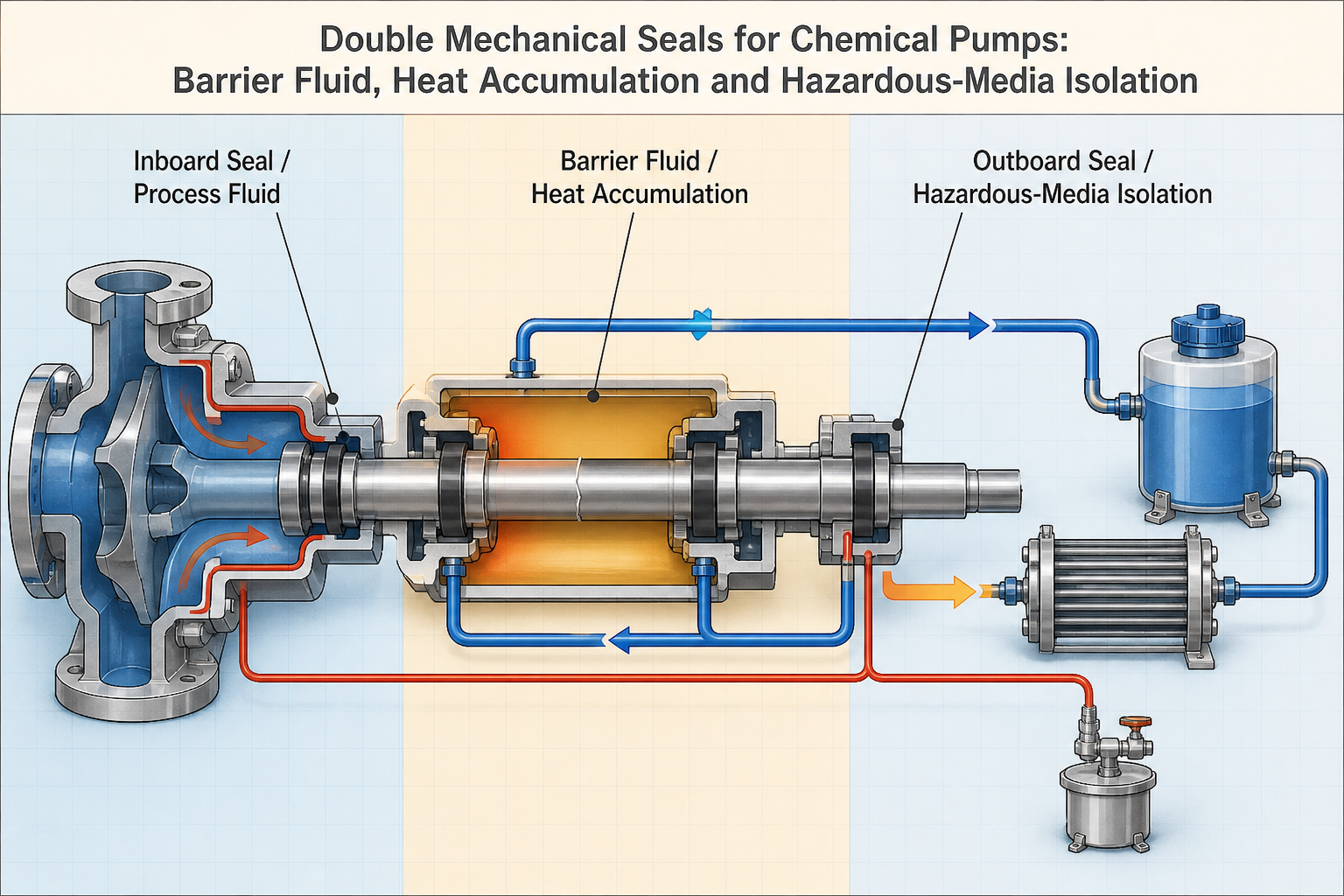
The pump shaft and sleeve transmit rotation through the seal chamber. The inboard seal limits process-fluid movement from the pump side; the outboard seal limits movement toward the atmosphere or the support-fluid side. Seal faces carry the sliding contact, while secondary seals, glands and static joints maintain the remaining boundaries. A reservoir, circulation circuit, cooler, pressure and temperature instruments, vents, drains and collection points form the support system around the seal faces.
Tandem and back-to-back arrangements have different pressure logic and leakage direction. Process fluid may enter barrier fluid through an inboard failure, while an outboard failure may first appear as support-fluid loss. A static gland or sleeve may bypass the faces. Map process fluid, barrier fluid, buffer fluid, atmosphere and controlled collection boundaries separately.
Table I: Chemical Pump Double-Mechanical-Seal Zones and Functions
|
Sealing zone |
Seal component |
Adjacent medium |
Main function |
Typical leakage path |
Verification focus |
| Inboard seal | Primary faces and secondary seals | Process fluid and support cavity | Limit process-fluid migration | Process fluid into barrier fluid | Fluid composition and face inspection |
| Outboard seal | Primary faces and gland seals | Support fluid and atmosphere | Limit external release | Barrier-fluid loss or emission | Level, pressure and external collection |
| Barrier-fluid cavity | Reservoir, circuit and cooler | Barrier fluid | Lubricate, cool and contain migration | Vaporization, ingress or loss | Pressure, level, temperature and sampling |
| Buffer-fluid circuit | Unpressurized or alternative support path | Buffer fluid and atmosphere | Provide defined secondary boundary | Contamination or uncontrolled migration | Pressure logic and fluid condition |
| Shaft-sleeve boundary | Sleeve and secondary seal | Rotating shaft region | Prevent bypass around faces | Sleeve leakage or wear path | Surface, runout and teardown |
| Static and collection boundary | Gland, housing, drains and vents | Process, support fluid and atmosphere | Direct release to controlled handling | Joint, fitting or drain leakage | Pressure test and collection review |
Each component must be assigned to a boundary and a detectable failure. A normal support-system signal does not certify the condition of both seal faces, the sleeve or static joints.
Barrier Fluid, Buffer Fluid and Pressure Control
Barrier-fluid, buffer-fluid and process pressures determine internal migration. A pressurized barrier system can provide a secondary boundary, lubrication and heat removal. A buffer system may be unpressurized or governed by different pressure logic, so it should not be interpreted as a pressurized barrier system.
Insufficient barrier pressure may reduce process-fluid exclusion. Excessive pressure may drive support fluid into the pump chamber, change face loading or increase outboard seal load. Pressure fluctuation can originate from leakage, temperature, gas entrainment, circulation change, reservoir behavior or instrument error. A falling level may indicate seal loss, evaporation, auxiliary-system leakage or sampling and replenishment effects.
Fluid selection must consider process-fluid compatibility, face and secondary-seal materials, shaft sleeve, viscosity, volatility, cleaning, downstream handling and hazard classification. No universal pressure difference, level, flow rate or refill interval applies to every chemical pump double seal.
Seal-Face Heat Generation and Heat Accumulation
Seal-face heat is generated by face loading, friction, sliding speed, lubrication regime, face opening and transient operation. The heat must pass through the faces, surrounding fluid, chamber and support circuit. If circulation is inadequate, a cooler is fouled, a line is blocked or gas is entrained, heat can accumulate and raise support-fluid temperature. Vapor formation, foaming, flashing, poor lubrication, face distortion, blistering, cracking and rapid wear may follow.
Seal-chamber, barrier-fluid and local face temperatures are not necessarily the same. Sensor location and response can hide a local hot spot. Temperature rise can also result from low flow, dry running, cavitation, process-fluid temperature change, friction increase or measurement error. Any thermal-balance or friction-power calculation is an illustrative engineering example and must be tied to the pump, seal arrangement, speed, fluid and test method.
Hazardous-Media Isolation and Leakage Paths
For toxic, flammable, corrosive or volatile process fluids, the double seal should direct migration toward a monitored, collected or treated boundary. Process-fluid ingress into barrier fluid may change pressure, temperature, color, viscosity or composition. Barrier-fluid ingress into the process may contaminate the product or alter process conditions. An outboard failure may release support fluid first, while a combined failure can allow process fluid to reach the atmosphere.
Other paths include static-seal leakage, shaft-sleeve bypass, reservoir or circuit leakage, drain or vent leakage, vaporization, foaming and sampling-system contamination. The absence of visible droplets does not prove hazardous-media isolation. Detection and collection must be designed with the fluid hazard, drain routing, vent routing, sampling method and personnel-protection boundary in mind.
Operating Conditions: Start-Up, Low Flow and Cycling
Before start-up, the seal chamber and support circuit should be filled, vented and circulating according to the system design. Delayed circulation or trapped gas can cause short dry-running exposure. Low-flow or dead-heading operation can reduce heat removal. Cavitation and gas entrainment can destabilize face lubrication. Variable speed changes sliding speed, frictional heat and support-system behavior, while frequent starts increase thermal and pressure cycling.
The pump and support system should have coordinated start and stop logic. A fixed minimum flow, waiting time or circulation time is not universal. Record filling, venting, speed, pressure, temperature, low-flow exposure, start-stop history, fluid condition and leakage trend.
Monitoring, Leakage Detection and Verification
Barrier pressure, level and temperature are useful signals but not complete diagnoses. Process pressure, seal-chamber temperature, differential pressure, fluid composition, viscosity or density, gas detection and collected leakage should be interpreted together. A pressure test checks a defined boundary; it does not replace dynamic rotation, speed, low-flow, start-stop or thermal-cycle verification.
A composition change may indicate process ingress, but contamination, evaporation, sampling error and temperature can create similar signals. Temperature rise may indicate friction, circulation loss, cooler fouling, low flow or process heating. Teardown should examine faces, cracks, deposits, secondary seals, sleeve marks and blocked lines.
Table II: Barrier Fluid, Heat Accumulation and Leakage-Risk Matrix
|
Operating factor |
Primary effect |
Secondary effect |
Potential failure mode |
Required measurement |
Main limitation |
| Barrier pressure low | Reduced process-fluid exclusion | Face-load change | Process ingress or external release | Pressure, composition and leak trend | Pressure alone does not identify face damage |
| Barrier pressure high | Support fluid driven toward process | Higher face or outboard load | Product contamination or wear | Differential pressure and sampling | Limit is system-specific |
| Fluid contamination | Property and lubrication change | Deposit or gas formation | Face wear or opening | Composition, viscosity and particles | Source may be ingress or handling |
| Circulation loss | Reduced heat removal | Vaporization or hot spot | Overheating and leakage | Flow, temperature and line inspection | Sensor location can hide local heat |
| Cooler fouling | Lower heat-transfer capacity | Support-fluid temperature rise | Face distress or flashing | Inlet/outlet temperature and flow | Trend needs process context |
| Low flow or dry running | Poor chamber cooling and lubrication | Rapid face heating | Blistering, cracking or wear | Flow, temperature and dynamic leakage | Short events may leave limited evidence |
| Gas entrainment or foaming | Unstable face film and circulation | Level or pressure fluctuation | Face opening or false alarm | Sight, level, pressure and sampling | May be process or support-system related |
The matrix separates mechanisms from signals. A single abnormal pressure or temperature value should trigger path-specific checks, not an automatic seal replacement.
Material and Interface Selection
Carbon, silicon carbide, tungsten carbide, resin-impregnated carbon, PTFE-based secondary seals, FKM, FFKM, EPDM, HNBR, graphite, filled PTFE, coated or hardened sleeves and composite systems may suit different pump boundaries. Comparison should include process and barrier-fluid compatibility, temperature, thermal conductivity, wear, face-pair behavior, friction, swelling, hardening, compression set, extrusion, particle tolerance, surface finish and cleaning.
No face pair, O-ring, packing or support fluid is a universal best choice. Selection must combine process chemistry, concentration, temperature, pressure, speed, seal arrangement, support fluid, lubrication, hazard, manufacturing tolerance and maintenance method.
Inspection, Testing and Maintenance
Inspect faces, secondary seals, shaft and sleeve, gland, chamber, reservoir, circulation pipes, cooler and instruments. Record pressure, temperature, fluid condition, calibration, dynamic leakage, low-flow behavior, start-stop response and teardown. Visual inspection cannot replace dynamic testing.
After replacing faces, clean the support circuit and confirm fluid compatibility, level, pressure, venting and circulation. Recheck leakage direction and alarm logic after replacing an inboard or outboard seal. A blocked line, valve, cooler or reservoir can imitate seal failure. Commissioning should confirm start sequence, support stability, temperature trend, hazardous-media detection and the affected dynamic boundary.
Data Interpretation and Maintenance Planning
Separate inboard, outboard, process ingress, support-fluid ingress, face, static and sleeve leakage from vaporization, foaming, heat accumulation and instrumentation error. A pressure, level, temperature or composition trend is a clue, not a diagnosis; correlate it with speed, process condition, low-flow events, circulation, sampling, calibration and teardown.
Maintenance can combine calendar, operating-hour, start-stop, leakage-trend, support-level, temperature, contamination and low-flow triggers. Laboratory hours, one leakage measurement, one refill or one cycle count must not be converted into universal seal life. Replacement should address the path and be followed by documented requalification.
FMEA Risk Analysis
The RPN values are illustrative engineering risk rankings, not field statistics or experimental results. They prioritize evidence for fluid selection, pressure control, heat removal, face integrity, hazardous-media containment and post-maintenance verification.
Table III: Chemical-Pump Double-Seal Monitoring and Verification Guide
|
Test or monitoring method |
Test objective |
Key variable |
Detectable issue |
Suitable stage |
Main limitation |
| Pressure and level monitoring | Track support-system state | Pressure, level and differential | Loss, ingress or unstable support | Continuous operation | Cannot prove both faces are healthy |
| Temperature monitoring | Identify heat accumulation | Barrier, chamber and process temperature | Circulation loss or hot spot | Operation and troubleshooting | Sensor location limits diagnosis |
| Fluid composition check | Detect process ingress or contamination | Chemistry, viscosity, density and particles | Cross-contamination or degradation | Operation and maintenance | Sampling and evaporation errors possible |
| Static pressure test | Check defined containment boundary | Pressure, dwell and temperature | Gross static leakage | Assembly and repair | Does not reproduce rotation |
| Dynamic leakage test | Assess face behavior in motion | Speed, pressure, temperature and flow | Face opening, wear or emission | Qualification and requalification | Requires safe test handling |
| Low-flow and start-stop test | Challenge thermal transients | Flow, sequence, speed and cycles | Dry running or transient heating | Qualification and troubleshooting | Profile must represent service |
| Teardown and calibration audit | Confirm mechanism and signal quality | Faces, seals, lines and instruments | Damage, blockage or false signal | Failure analysis and repair | Destructive and history-dependent |
For hazardous media, the record should also identify test fluid, drainage, vent routing, sampling, collection and personnel-protection controls.
Table IV: Chemical-Pump Double-Mechanical-Seal FMEA and RPN Analysis
|
Failure mode |
Cause |
Local effect |
System effect |
Detection method |
RPN |
Corrective action |
| Incorrect barrier or buffer fluid | Poor compatibility or wrong pressure logic | Property or film change | Ingress, wear or contamination | Fluid review and sampling | 180 | Match fluid and pressure logic to arrangement |
| Insufficient barrier pressure | Leak, gas entry or control error | Reduced process exclusion | Hazardous-media migration | Pressure, level and composition | 195 | Control pressure and investigate loss |
| Excessive barrier pressure | Incorrect setting or thermal expansion | Load shift toward process | Product contamination or outboard load | Differential pressure and sample | 180 | Define system-specific pressure window |
| Inadequate circulation | Blocked line, valve or gas entrainment | Heat removal loss | Vaporization or face opening | Flow and temperature trend | 190 | Inspect, vent and verify circuit |
| Cooler fouling | Poor heat transfer or wrong utility | Support-fluid heating | Heat accumulation and wear | Inlet/outlet temperature and flow | 175 | Clean, inspect and trend heat removal |
| Face overheating or opening | Low flow, dry running or load change | Film loss and wear | Leakage, cracking or emission | Temperature, dynamic leak and teardown | 200 | Control operation and restore lubrication |
| Inboard seal leakage | Face damage, pressure or contamination | Process enters support fluid | Cross-contamination and warning signal | Composition, pressure and teardown | 195 | Identify path and requalify inboard seal |
| Outboard seal leakage | Wear, overload or secondary-seal damage | Support fluid loss or release | External emission or containment loss | Level, collection and gas detection | 200 | Inspect outboard boundary and collection |
| Shaft or sleeve damage | Runout, scoring or particles | Secondary bypass path | Persistent leakage and friction | Runout, surface and teardown | 175 | Correct alignment and surface condition |
| Instrumentation error | Drift, wrong location or sampling issue | False pressure, temperature or level signal | Wrong maintenance decision | Calibration and cross-check | 155 | Audit instruments and measurement method |
| Incorrect assembly or requalification | Wrong seal, fluid, sequence or test | Unverified support state | Repeat failure after repair | Work record and dynamic test | 190 | Use controlled procedure and path-specific test |
Risk reduction is credible only when it improves the physical control, measurement method or decision rule. Lowering an RPN without better evidence does not improve double-seal reliability.
Conclusion
Double mechanical seals for chemical pumps are controlled hazardous-media isolation systems. Inboard and outboard seal behavior, barrier or buffer fluid pressure, face lubrication, heat removal, circulation and process compatibility determine whether migration is contained and detectable. Pressure normality or one static test cannot prove long-term integrity during low flow, dry running, cycling or heat accumulation.
A defensible program connects support-fluid monitoring, dynamic tests, temperature and pressure trends, composition checks, safe collection, teardown and requalification. The objective is a defined path, controlled containment, early warning and verified correction, not zero leakage.
Engineering FAQ
Q:What is the difference between a barrier fluid and a buffer fluid in a double mechanical seal?
A:A barrier fluid forms a controlled support boundary with defined pressure, lubrication and cooling functions. A buffer fluid may use different pressure and containment logic; the arrangement determines its role.
Q:How does barrier-fluid pressure affect hazardous-media isolation?
A:Pressure changes migration direction and face loading. Too little may reduce process exclusion; too much may drive support fluid into the process or load the outboard seal. Evaluate it with arrangement and process pressure.
Q:Why can seal-face heat accumulation cause leakage in a chemical pump?
A:Friction and face loading generate heat. Poor circulation, cooler fouling, gas entrainment, low flow or dry running can prevent removal, causing vaporization, lubrication loss, distortion, wear or face opening.
Q:What does a falling barrier-fluid level indicate?
A:It may indicate outboard loss, process ingress, vaporization, auxiliary leakage, sampling or replenishment effects. Confirm with pressure, temperature, composition, collection records and inspection; level alone does not prove face failure.
Q:How can process-fluid ingress into the barrier system be detected?
A:Use composition, viscosity, density or particle trends with pressure, temperature and level records. Exclude sampling error, evaporation and contamination; teardown may be needed to confirm the path.
Q:Does normal barrier-fluid pressure prove that both mechanical seals are healthy?
A:No. Pressure can remain normal despite face wear, static leakage, sleeve bypass, a blocked measurement path or an outboard defect. Combine pressure with level, temperature, composition, dynamic leakage and inspection.
Q:Which checks are required after replacing a chemical-pump double mechanical seal?
A:Confirm face and secondary-seal installation, shaft condition, clean lines, compatible fluid, fill, venting, pressure, circulation, alarm logic, dynamic leakage, temperature trend and hazardous-media collection before return to service.
Q:How should temperature, pressure and leakage trends be interpreted together?
A:Correlate operating condition, support state and leakage path. Temperature rise can reflect friction, low flow or cooling loss; pressure change can reflect migration or instrumentation. Use trends to select a path-specific test, not assign a cause.
Post time: Sep-01-2026