
Executive Summary
Dynamic O-ring sealing is a tribological problem, not a static compression problem with motion added afterward. The seal must maintain contact pressure while sliding against a shaft, rod, piston or sleeve. Frictional work is produced at the dynamic contact band, converted into local heat, and then redistributed through the elastomer, metal hardware and lubricant. Initial low leakage therefore says little about what will happen after speed changes, start-stop cycling, temperature drift, contamination and wear particles accumulate.
Service life depends on compound, groove, squeeze, pressure differential, sliding speed, stroke or rotation, lubrication, surface finish, heat dissipation and particle control. Low friction is not identical to low wear; falling friction may indicate contact-pressure loss. The useful question is whether the interface preserves sealing margin while limiting heat, stabilizing the film, controlling particles and leaving inspectable surfaces.
Dynamic O-Ring Architecture and Contact Boundary
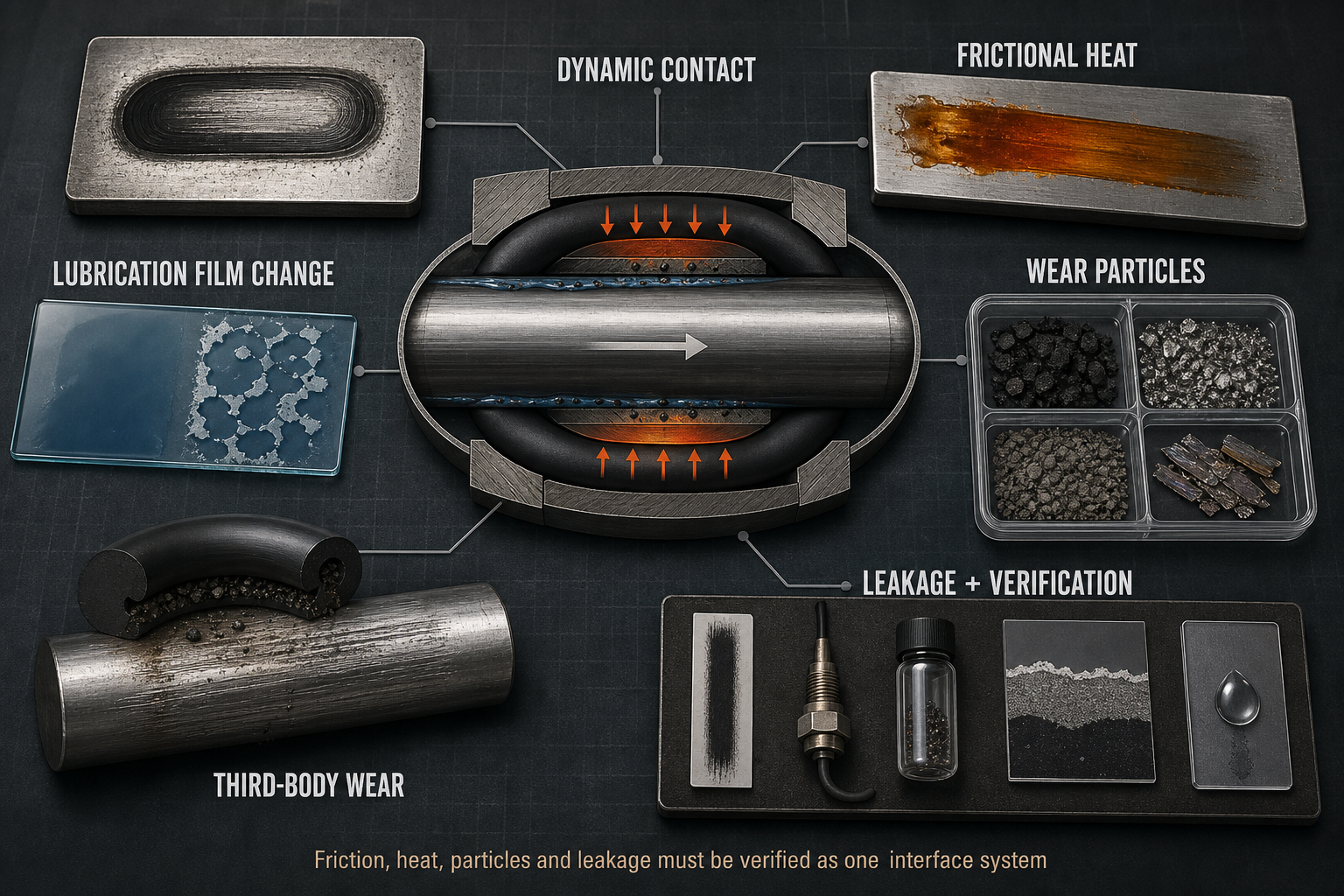
A dynamic O-ring forms a boundary between the high-pressure side, low-pressure side, groove support zone and moving counterface. The O-ring may contact a shaft, rod, piston, sleeve or valve stem while the groove controls squeeze, extrusion clearance and pressure loading. The dynamic contact zone is where sliding, local stick-slip, lubricant shear, heat generation, transfer-film formation and wear-particle release occur. The static groove wall can simultaneously experience compression set, twisting, rolling or nibbling.
Reciprocating and rotating applications must be separated. In reciprocation, reversal zones experience changing film thickness, start-up friction and debris re-entry. In rotation, circumferential speed, runout and continuous heat accumulation become dominant. A pressure reversal or eccentric shaft can move the contact band to one side and create a local hot track before any visible leak appears. Wear particles may migrate with motion, fluid flow or lubricant displacement and later return as third-body abrasives.
Table I. Dynamic O-Ring Sealing Zones and Functions
| Seal zone | Adjacent component or medium | Dynamic function | Main friction or wear risk | Leakage consequence | Verification focus |
| Contact band | Shaft, rod or piston | Sliding containment | Heat and film loss | Dynamic leakage | Friction and leak trend |
| Groove wall | Housing and trapped fluid | Compression support | Twist or set | Contact-pressure loss | Dimension and set check |
| Extrusion gap | Pressure side clearance | Gap control | Nibbling and extrusion | Edge bypass | Clearance and edge inspection |
| Low-pressure side | Return flow or atmosphere | Leak exit path | Particle migration | Visible leakage | Debris and fluid check |
| Counterface | Metal or coating | Motion surface | Scoring or polishing | Wear-induced leak | Roughness and morphology |
The table separates where heat is generated, support is lost and particles travel. A valid diagnosis must inspect the O-ring, groove, counterface and lubricant path together.
Contact Pressure, Sliding Motion and Frictional Heat
Friction behavior is governed by contact pressure, squeeze, interference, pressure differential, material formulation, surface finish, lubricant condition and speed. Higher squeeze can raise sealing margin but also increases friction force and heat generation. Insufficient squeeze may reduce heat but can destabilize the lubrication film and reduce leakage resistance. The friction coefficient is therefore a result of the interface state, not a fixed material property.
Frictional heat is generated locally where the O-ring and counterface slide. Measured housing, oil or bulk seal temperature may be lower than local flash temperature. Poor dissipation may soften the elastomer, increase volume, reduce elastic recovery, thin the lubricant, promote adhesive wear, or create thermal hardening and thermal aging depending on material and medium. No single alarm temperature is universal.
Motion history controls the thermal pattern. Low-speed start-up may produce boundary contact and stick-slip because the film is not yet stable. Reversal in a cylinder can wipe lubricant away and pull debris back into the seal. High circumferential speed in rotation can create continuous heat input with limited cooling. Stroke length, dwell time and pressure cycling decide whether heat dissipates between movements or accumulates until friction, actuation force and wear accelerate.
Table II. Frictional Heat, Lubrication and Wear-Risk Matrix
| Operating factor | Primary effect | Secondary effect | Potential failure mode | Required measurement | Main limitation |
| High squeeze | Contact pressure rises | Friction heat increases | Wear or force drift | Squeeze and friction | Geometry specific |
| Low squeeze | Contact margin falls | Film instability | Dynamic leakage | Leak and compression | May reduce friction |
| High speed | Friction power rises | Thermal accumulation | Heat damage | Speed and temperature | Sensor may miss flash heat |
| Poor lubrication | Boundary contact | Adhesive wear | Stick-slip and debris | Friction and lubricant | Film not directly visible |
| Rough surface | Asperity cutting | Hard debris | Abrasive wear | Roughness and particles | Sampling sensitive |
| Runout or misalignment | Uneven loading | Local hot track | Scoring and leakage | Runout and wear map | Requires assembly data |
The matrix is not a universal limit table. Each factor must be interpreted with the actual material, groove, counterface, medium, pressure, speed and measurement position.
Lubrication Film, Surface Finish and Particle Generation
Lubrication decides whether contact operates in boundary, mixed or fluid-supported conditions. Too little lubricant increases shear, adhesion and heat. Too much or incompatible lubricant can cause chemical swelling, extraction, debris trapping or migration away from the active band. Viscosity changes with temperature and shear; cold start raises friction, while heat can thin the film or accelerate oxidation.
Surface finish is not simply “smoother is better.” A rough shaft can cut the O-ring and release rubber fragments or filler-rich debris. A surface that is too smooth may retain too little lubricant, increasing stick-slip. Directional grinding marks, waviness, coating defects, runout and eccentricity can concentrate pressure and create a repeating hot or polished track. Surface polishing, stable transfer film and true material loss must be separated through morphology and composition analysis.
Wear particles may originate from the O-ring body, released filler, metal counterface, coating fragments, external contamination, deposits or unstable transfer film. Hard particles can roll, cut or plough as third bodies; soft rubber fragments can block micro-paths, thicken lubricant locally or re-enter the contact during reversal. Particle increase may appear before leakage because debris formation, surface scoring and contact instability precede a continuous leak path. Particle counts must be checked against sampling, cleaning and fluid-change effects.
Geometry, Extrusion and Motion Stability
Groove geometry turns tribology into failure. Cross-section, radial or axial squeeze, groove fill, pressure direction, clearance, edge radius, backup support and installation stretch define how the O-ring moves under load. Excessive squeeze raises frictional heat and actuation force. Insufficient squeeze can reduce contact pressure and allow leakage or film instability. Large clearance, high pressure and thermal softening can drive extrusion, nibbling and edge particle generation.
Motion instability produces failure modes that can be misread as poor wear resistance. Spiral twist, rolling, local slip and seal rotation change the stress distribution and expose new surface regions to heat. Reciprocating reversal, pressure reversal, shaft runout, eccentricity and misalignment can generate alternating hot spots. A backup ring may control extrusion, but it cannot correct poor lubrication, an eccentric counterface or a twisted O-ring installed with contamination in the groove.
Leakage Diagnosis, Testing and Service-Life Control
Dynamic leakage can result from wear, extrusion, contact-pressure loss, compression-recovery loss, shaft scoring, lubricant failure, permeation or test-system leakage. Pressure decay needs temperature, medium, volume and sensor context. Friction rise may come from heat, dry contact, swelling, contamination, surface damage or misalignment; temperature rise may reflect friction, external heat, medium temperature, sensor position or temperature-measurement error. Friction-measurement error must also be excluded.
Verification should combine dynamic leakage, friction force or torque, contact temperature, particle analysis, lubricant analysis, surface inspection, hardness mapping, dimensional inspection and cross-sectional microscopy. Static leakage tests and static immersion can screen compatibility, but they cannot reproduce speed, reversal, frictional heating or third-body wear. After abnormal particles or heat, preserve the O-ring, counterface and lubricant before cleaning so that particle shape, transfer film and surface morphology remain available.
Service-life planning should record seal type, motion, geometry, compound, batch, hardness, clearance, pressure, speed, stroke or rotation, lubricant, viscosity, roughness, runout, alignment, temperature, friction trend, leakage trend, particle trend and maintenance history. A single run, one low-leak result or one particle sample is only a tested-configuration observation.
Table III. Dynamic O-Ring Testing and Verification Guide
| Test or inspection | Test objective | Key variable | Detectable issue | Suitable stage | Main limitation |
| Dynamic leak test | Measure containment in motion | Speed, pressure, stroke | Motion leakage | Validation | Setup specific |
| Friction monitoring | Track force or torque | Load and speed | Stick-slip or heat risk | Development and service | Needs baseline |
| Temperature monitoring | Find heat trend | Sensor location | Thermal accumulation | Validation | May miss flash heat |
| Particle analysis | Identify debris source | Shape and composition | Third-body wear | Failure analysis | Sampling sensitive |
| Surface inspection | Map counterface damage | Roughness and scoring | Abrasive or adhesive wear | Before and after test | Requires reference state |
| Cross-section microscopy | Inspect seal damage | Cut face and edge | Extrusion, cracks or set | Failure analysis | Destructive |
Testing must follow the same motion, pressure, lubricant and surface conditions that create the field risk. Otherwise the result verifies only the test fixture.
Material, Surface and Maintenance Decisions
NBR, HNBR, FKM, EPDM, FFKM, silicone, polyurethane and PTFE-based dynamic elements may differ in friction behavior, heat resistance, recovery, tear strength, chemical compatibility, lubricant compatibility and particle generation. Filled, low-friction, wear-resistant, high-temperature and low-compression-set compounds all carry trade-offs. Surface-treated shafts, hardened rods, coatings and engineered backup rings are also part of the tribological pair. No material, hardness, filler, coating or lubricant can eliminate frictional heat and wear in every dynamic O-ring application.
Maintenance should not stop at replacing the ring. The groove, clearance, counterface roughness, runout, lubricant, contamination, assembly twist and initial run-in procedure must be checked. If the same shaft scoring, debris source or lubricant starvation remains, the new O-ring may repeat the old failure. Post-repair dynamic requalification should include leakage, friction, temperature and particle checks under representative motion.
FMEA Risk Analysis
The RPN values in the following table are illustrative engineering risk rankings, not field statistics or experimental results. They should be recalculated using the organization’s severity, occurrence and detection definitions.
Table IV. Dynamic O-Ring Friction and Wear FMEA
| Failure mode | Cause | Local effect | System effect | Detection method | RPN | Corrective action |
| Friction heat buildup | High squeeze or speed | Hot contact band | Wear and leakage | Temperature and force | 245 | Revise squeeze, speed and cooling |
| Film failure | Starvation or viscosity drift | Boundary contact | Adhesive wear | Friction and lubricant | 230 | Correct lubricant and supply path |
| Abrasive wear | Rough shaft or hard debris | Cutting and scoring | Leak path | Particles and microscopy | 250 | Improve finish and cleanliness |
| Third-body wear | Debris trapped in contact | Rolling or ploughing | Accelerated wear | Particle morphology | 235 | Improve flushing and filtration |
| Excess squeeze | Groove or size error | High force | Heat and actuation load | Dimensional check | 210 | Correct groove and size |
| Low squeeze | Set or undersize seal | Contact loss | Dynamic leakage | Compression and leak | 205 | Restore compression margin |
| Extrusion or nibbling | Gap, pressure, softening | Edge damage | Debris and leakage | Edge cross-section | 240 | Reduce gap or add support |
| Runout or misalignment | Assembly or bearing error | Local hot track | Uneven wear | Runout and wear map | 220 | Correct alignment and support |
| Poor verification | Static-only testing | Hidden wear risk | Repeat failure | Test-matrix audit | 255 | Add dynamic heat and particle tests |
Conclusion
Dynamic O-ring sealing reliability is determined by contact pressure, sliding motion, lubrication-film stability, frictional heat, heat dissipation, wear mechanisms and particle control. Leakage is often the last visible result, not the first sign of failure. Friction, temperature and particles may drift before a continuous leakage path forms.
A defensible life assessment must distinguish frictional heat from bulk temperature, abrasive wear from adhesive wear, third-body wear from contamination, extrusion from material wear, and dynamic leakage from test-system leakage. The engineering answer is not a universal material or surface finish; it is a verified interface combining compound, groove, counterface, lubricant, motion envelope, cleanliness and post-test evidence.
Engineering FAQ
Q:Why does a dynamic O-ring generate frictional heat?
A:Sliding contact converts frictional work into local interface heat.
Q:How do sliding speed and contact pressure affect seal temperature?
A:They change friction power, stress and heat-dissipation balance.
Q:What is the difference between abrasive wear and adhesive wear?
A:Abrasive wear cuts surfaces; adhesive wear tears or transfers material.
Q:Where do wear particles come from?
A:From the O-ring, filler, shaft, coating, contamination, deposits or transfer film.
Q:Can a low-friction O-ring still generate significant wear?
A:Yes. Low friction does not prove stable film, pressure or particle control.
Q:How do roughness and lubrication affect particle generation?
A:They control cutting, film stability, debris trapping and third-body abrasion.
Q:Why can friction increase before leakage appears?
A:Heat, debris and surface damage can accumulate before a leak path opens.
Q:Which tests are needed after abnormal heat or particles?
A:Use dynamic leakage, friction, temperature, particle, lubricant, surface and cross-section analysis.
Q:How should dynamic O-ring service life be evaluated?
A:Evaluate trends under representative motion, pressure, temperature, lubricant and surface conditions.
Post time: Sep-04-2026