
Executive Summary
An e-axle reducer oil seal operates at a different boundary condition from a low-speed gearbox seal. The shaft may rotate rapidly, the gears may agitate lubricant, and the seal interface must manage sliding speed, frictional heat, oil-film stability and shaft motion at the same time. Reliability therefore depends on rotational speed, seal-lip contact, lubricant condition, oil aeration, foam behavior, shaft runout, surface condition, housing alignment, temperature and installation quality.
A static leakage result is only one observation. It does not show how the lip behaves at target speed, during speed ramps, after oil temperature rises, or when radial runout changes the contact pattern. Dynamic verification should combine leakage, friction torque, temperature, lubricant observation, shaft geometry and post-test morphology. No single oil-seal material or structure removes every high-speed leakage, foaming or alignment risk.
E-Axle Reducer Oil-Seal Architecture
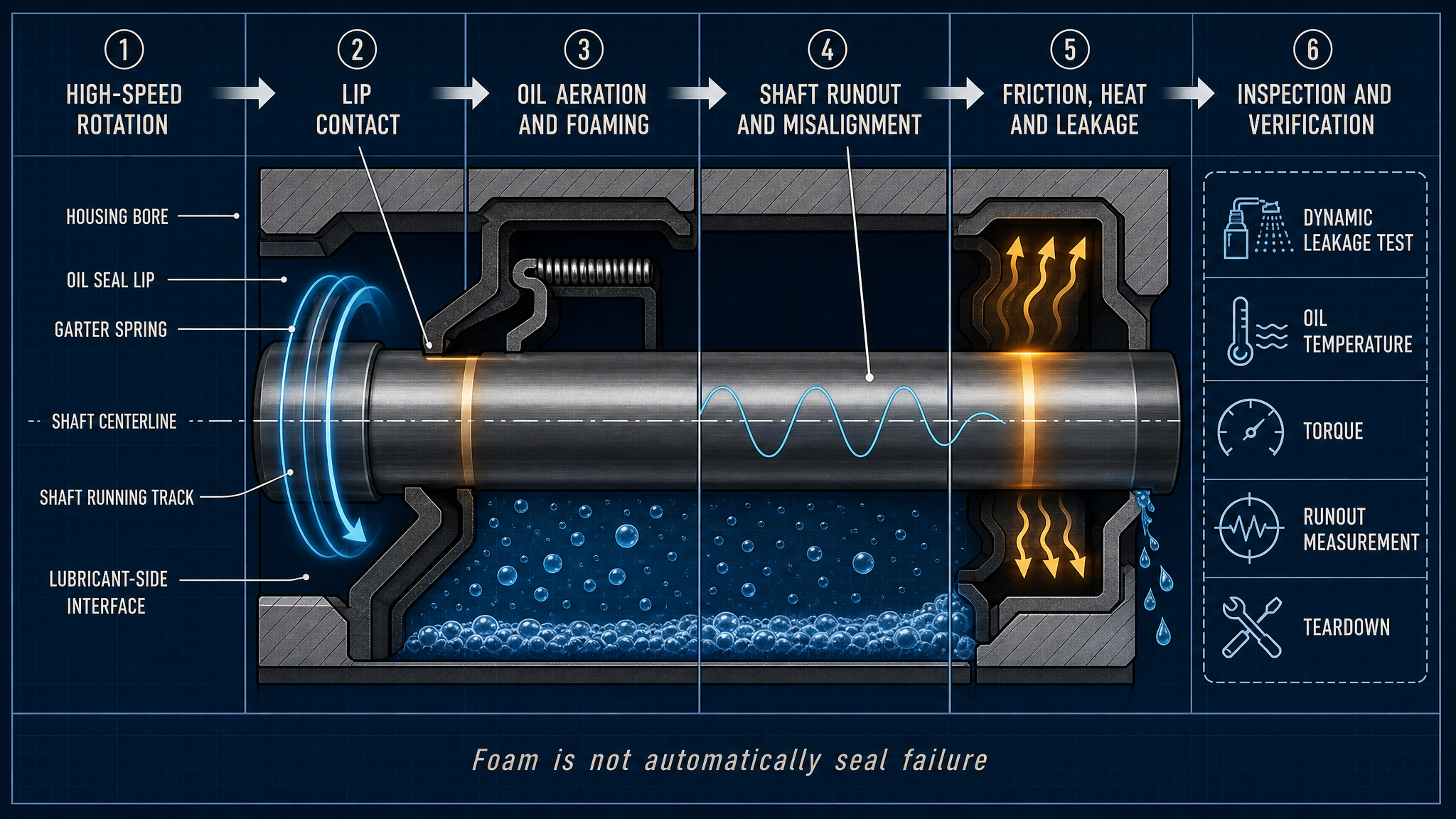
The sealing assembly normally includes a reducer housing, an input or output shaft, a seal carrier, a housing bore, a rotary seal lip and a garter spring. The lubricant-side interface faces the oil space; the atmospheric-side interface faces the outside environment. An auxiliary dust lip may limit contamination entry, but it is not a substitute for the main oil-sealing lip.
The garter spring maintains radial contact while the lip, shaft surface and lubricant film form the working interface. Shaft sleeves or hardened tracks can provide a controlled running surface, but their finish, concentricity and damage tolerance remain design-specific. Housing-bore condition and press-fit depth determine whether the seal axis is stable. Sealing capability, low friction, high-speed stability and service life must be evaluated separately.
Table I: E-Axle Reducer Oil-Seal Operating Factors
|
Operating factor |
Seal-interface effect |
Likely symptom |
Verification focus |
Main limitation |
| Shaft speed | Sliding velocity and heat rise | Friction or leakage change | Dynamic speed test | Design-specific |
| Oil temperature | Viscosity and material change | Film instability | Temperature and leakage record | Thermal-history dependent |
| Oil level | Wetting and churning change | Starvation or foam | Oil-level inspection | Geometry dependent |
| Shaft runout | Periodic contact variation | Intermittent leakage | Runout and teardown | Root cause may be upstream |
| Installation condition | Seating and orientation change | Early leakage | Visual and dimensional check | Requires access |
These factors interact at the lip interface. A single symptom should not be assigned to one factor without supporting geometry, lubricant and dynamic evidence.
High-Speed Rotation, Friction and Heat
Increasing shaft speed raises sliding velocity and can increase friction torque and local heat generation. The lip must maintain contact without producing excessive drag, while a thin lubricant film must separate enough of the surfaces to control wear. If the film becomes unstable, contact temperature and wear may rise even when the static seal appears acceptable.
Temperature changes lubricant viscosity, elastomer modulus, elastic recovery and thermal expansion. Start-stop cycles and speed ramps can create transient conditions different from steady operation. Heat must be considered across the lip, shaft track, lubricant and housing because local cooling and oil distribution may not be uniform. Fixed speed, temperature-rise or friction values should not be treated as universal e-axle standards.
Oil Aeration, Foaming and Seal Lubrication
Oil foaming is a visible or persistent foam layer. Oil aeration describes air dispersed through the lubricant, while entrained air is gas carried within the oil stream. These conditions may coexist but are not identical. Air-release behavior depends on lubricant formulation, temperature, viscosity, agitation and residence time. Cavitation-related vapor formation is a separate pressure-related phenomenon and is mentioned here only as background, not as the primary subject.
Gear churning, oil level, return paths and local turbulence can increase air content or foam persistence. At the seal lip, aerated oil may change film continuity, local pressure fluctuation and heat transfer. A foam layer can alter wetting or oil delivery, while lubricant starvation means the contact zone is not receiving sufficient lubricant; starvation is not simply proof of low overall oil level.
Foaming does not automatically mean seal failure. Leakage, aeration and inadequate lubrication may influence one another, but each needs separate evidence. Oil level, temperature, speed, lubricant condition, foam persistence, leakage and lip morphology should be reviewed together before assigning a root cause.
Table II: High-Speed Rotation, Oil Aeration and Shaft-Runout Matrix
|
Stress factor |
Primary effect |
Secondary effect |
Potential failure mode |
Required measurement |
Main limitation |
| High-speed rotation | Sliding velocity rises | Frictional heat | Lip wear or overheating | Speed, torque, temperature | No universal speed limit |
| Oil aeration | Film continuity changes | Heat transfer shifts | Lubrication instability | Air-release and oil observation | Oil-specific behavior |
| Foam accumulation | Local wetting changes | Pressure fluctuation | Intermittent leakage | Foam persistence and level | Observation is conditional |
| Shaft runout | Contact pressure cycles | Local lip pumping | Lip wear or leakage | Radial runout | Bearing or shaft root cause |
| Axial movement | Lip track shifts | Contact loss | Intermittent leakage | Axial displacement | Load dependent |
| Housing misalignment | Seal axis changes | Uneven wear | Premature leakage | Bore alignment | Assembly dependent |
The matrix separates high-speed, lubricant and shaft-system effects. Similar leakage symptoms can still require different corrective actions.
Shaft Runout, Eccentricity and Alignment
Radial runout makes lip contact pressure vary during each revolution. Excessive eccentricity can produce a high-contact region with accelerated wear and a low-contact region with intermittent loss of sealing. Axial shaft movement can shift the lip track, while shaft bending, bearing clearance, housing-bore misalignment or gear loading can change the seal axis.
The resulting symptoms may include an uneven wear track, lip pumping, intermittent leakage or a polished band that does not match the intended contact path. Grooves, burrs, roughness changes and previous seal marks on the shaft can accelerate damage. Runout is therefore a shaft-system issue, not merely a seal-material issue. Replacing the seal without checking the shaft, bearing, bore and assembly condition may leave the cause unchanged.
Oil Level, Churning and Lubrication Distribution
Splash lubrication depends on oil level, gear motion, housing geometry and return paths. Too much agitation can increase air entrainment and heat, while a local region may still experience insufficient wetting. A high oil temperature can reduce viscosity and change both churning losses and lip-film behavior. The relevant condition is the lubricant state at the seal interface, not only the nominal oil quantity.
Inspection should distinguish local oil accumulation, restricted return, abnormal churning, aerated flow and true starvation. These conditions can produce similar temperature or leakage symptoms but require different corrective actions. The lubrication assessment should use the actual reducer geometry, lubricant, speed profile and thermal history.
Material and Interface Selection
FKM, HNBR, ACM, PTFE-based rotary seals, elastomeric lips, low-friction designs, coated sleeves and hardened shaft surfaces may be suitable for different designs. Selection should consider oil and additive compatibility, temperature, friction, wear, elastic recovery, swelling, hardening, high-speed stability, debris generation, shaft-surface requirements and assembly tolerance.
Temperature capability alone is not enough. A material may resist one lubricant but swell in another; a low-friction design may require a controlled shaft finish; a hard running surface may reduce wear but increase sensitivity to contamination or installation damage. The seal, shaft track, housing bore and lubricant must be treated as one interface system. No material is a universal best solution for every e-axle reducer.
Inspection, Testing and Maintenance
A static leakage test checks a stationary boundary but cannot represent high-speed contact. Dynamic rotation testing should observe leakage, speed, friction torque, oil temperature and, where possible, lubricant aeration. Speed-ramp and start-stop tests reveal hidden transitions. Foam observation is useful evidence but cannot independently prove seal failure.
Runout and concentricity inspections examine the shaft system; surface and bore inspections examine the running track and press-fit. Teardown should record lip wear, uneven contact, heat damage, spring displacement, deposits, shaft tracks, contamination and installation marks. Each method has a limitation, so no single test represents long-term reliability.
After replacement, confirm orientation, lip protection, press-fit depth, spring position, shaft condition, bore cleanliness and tooling. Requalify under representative speed, temperature, lubricant and leakage conditions.
Table III: E-Axle Oil-Seal Verification Guide
|
Test or inspection |
Test purpose |
Key variable |
Detectable issue |
Suitable stage |
Main limitation |
| Static leakage test | Check stationary boundary | Leakage and pressure | Gross sealing defect | Assembly screening | Does not represent high speed |
| Dynamic rotation test | Check running seal | Speed, leakage, torque | Lip instability | Design validation | Requires controlled rig |
| Speed-ramp test | Observe transition behavior | Speed and temperature | Speed-related change | Qualification | Profile dependent |
| Oil-foam observation | Assess aeration behavior | Foam and air release | Persistent foam | Lubrication study | Visual observation limited |
| Runout inspection | Check shaft geometry | Radial and axial runout | Eccentric contact | Manufacturing and repair | Does not prove lip condition |
| Shaft-surface inspection | Check seal track | Roughness and damage | Grooves or scoring | Assembly and teardown | Criterion is design-specific |
| Teardown inspection | Identify physical mechanism | Lip, spring and track | Wear, heat or damage | Failure analysis | Requires disassembly |
| Post-maintenance verification | Confirm restored condition | Leakage, speed and temperature | Assembly recurrence | Return to service | Must match actual duty |
The guide links static boundary checks, dynamic operation, lubricant state, shaft geometry and physical morphology rather than treating one result as proof of reliability.
Data Interpretation and Maintenance Planning
Useful records include reducer type, shaft speed and diameter, seal design and material, lubricant type and viscosity, oil level, oil temperature, foam or aeration observation, radial and axial runout, bearing and bore condition, leakage trend, friction torque, speed-cycle history, assembly condition, teardown morphology and corrective action.
Maintenance may be calendar-, mileage-, operating-cycle-, leakage-trend- or temperature-trend-based. Condition-based decisions should distinguish lip wear, shaft damage, housing misalignment, oil aeration, starvation and sensor or test variation. Laboratory rotation counts, fixed mileage or one temperature result must not be converted directly into a universal vehicle life.
FMEA Risk Analysis
The RPN values are illustrative engineering risk rankings, not field statistics or experimental results.
Table IV: E-Axle Reducer Oil-Seal FMEA and RPN Analysis
|
Failure mode |
Cause |
Local effect |
System effect |
Detection method |
RPN |
Corrective action |
| Lip wear | High speed or unstable lubrication | Contact loss | Oil leakage | Dynamic test and teardown | 240 | Review speed, oil and lip design |
| Shaft runout | Shaft, bearing or assembly error | Periodic contact change | Intermittent leakage | Runout measurement | 252 | Correct shaft-system alignment |
| Oil aeration | Churning, oil level or lubricant behavior | Film instability | Heat and leakage variation | Oil observation and temperature trend | 224 | Review oil level and lubricant condition |
| Frictional overheating | Excessive contact or cooling limitation | Lip property change | Accelerated degradation | Torque and temperature monitoring | 216 | Reduce heat source and verify materials |
| Installation damage | Wrong orientation or press-fit depth | Local lip damage | Early leakage | Assembly inspection and teardown | 245 | Control tooling and records |
| Housing-bore misalignment | Manufacturing or deformation | Uneven lip tracking | Premature wear | Bore and concentricity inspection | 210 | Correct housing geometry |
| Post-maintenance verification failure | Incomplete test | Defect remains undetected | Repeat field leakage | Requalification record review | 196 | Require return-to-service testing |
The FMEA separates seal, shaft, housing, lubricant and maintenance risks because they require different controls. A ranking is not field frequency; it indicates where detection and corrective action deserve engineering attention.
Conclusion
E-axle reducer oil-seal reliability is governed by the interaction of high-speed rotation, lip contact, lubricant aeration and foaming, shaft runout, frictional heat and housing alignment. Oil foaming is not automatically seal failure, and shaft runout is not simply a material-aging problem. Leakage is an outcome that requires evidence from the lip, shaft, lubricant and structure.
Reliable validation combines dynamic leakage, speed and temperature history, friction torque, oil-state observation, runout measurement, surface inspection and teardown. Post-maintenance verification must confirm orientation, press-fit depth, shaft condition, lubricant state and representative running behavior. The correct conclusion must follow the specific reducer, seal, lubricant, shaft geometry and test method rather than a universal material or life claim.
Engineering FAQ
Q:Why are e-axle reducer oil seals difficult at high speed?
A:High speed increases sliding velocity and frictional heat while reducing the margin for stable lip contact. The seal must control leakage without excessive drag, temperature or wear under changing lubricant and shaft conditions.
Q:How can oil foaming affect rotary oil-seal performance?
A:Foam and aerated oil can change wetting, film continuity, local pressure fluctuation and heat transfer near the lip. The effect depends on oil formulation, temperature, speed, oil level and foam persistence; foam alone does not prove seal failure.
Q:How does shaft runout cause intermittent oil leakage?
A:Runout makes lip contact pressure vary around the rotation. One region may wear excessively while another loses contact periodically, producing a leakage pattern that may appear only at speed or under certain loads.
Q:Can a static leakage test prove high-speed oil-seal reliability?
A:No. Static testing checks a stationary boundary. High-speed reliability requires dynamic rotation, speed transitions, oil-temperature observation, friction or torque evidence and post-test inspection under representative conditions.
Q:What should be checked when replacing an e-axle reducer oil seal?
A:Check orientation, spring position, lip protection, press-fit depth, shaft track, runout, housing bore, cleanliness, lubricant condition and installation tooling. Requalify leakage and running behavior after assembly.
Q:How can oil aeration be distinguished from an oil-seal failure?
A:Compare foam persistence, air-release behavior, oil level, temperature, speed, leakage, torque and teardown morphology. Aeration may exist without leakage, while a worn lip may leak without creating stable foam.
Post time: Aug-29-2026