
Executive Summary
Alkaline electrolyzer end-plate sealing is a system-level boundary problem. End-plate geometry, gasket compression, stack alignment, compression uniformity, chemical compatibility and cycling history determine whether alkaline solution, pure water and gas-side spaces remain separated. The gasket is only one element in a load path that also includes bipolar plates, diaphragms or separators, grooves, manifolds, tie rods and the compression frame.
The principal reliability risk is not simply that a material may be “not alkali resistant.” A leak can result from insufficient or excessive compression, local gap, end-plate distortion, fastener-load loss, chemical swelling, hardening, softening, compression-set loss, extrusion, contamination or incorrect assembly. External leakage, internal fluid crossover, gas-to-liquid leakage and permeation are different failure categories and require different evidence.
A single static pressure hold or one-medium immersion result cannot represent long-term stack compression stability. Thermal, chemical, pressure and start-stop cycling can change contact pressure and load distribution after initial assembly. Qualification and maintenance verification should therefore combine dimensional inspection, medium-specific tests, differential-pressure tests, cycling, fluid analysis, torque or compression records and post-test teardown.
Electrolyzer Stack and End-Plate Sealing Architecture
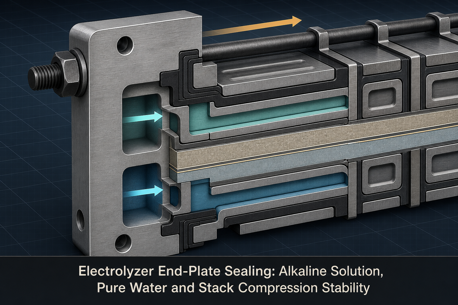
An alkaline electrolyzer stack creates several adjacent boundaries rather than one continuous seal. End plates transfer clamping load into the stack. Bipolar plates define cell interfaces and manifolds. Diaphragms or separators support the intended electrochemical partition, while gaskets establish local barriers around liquid channels, gas spaces and external edges. Grooves control gasket location and deformation; tie rods or a compression frame maintain the assembly load.
Leakage paths include alkaline solution or pure water to the exterior, alkaline-to-water crossover, water-to-alkaline crossover, gas-to-liquid leakage and local manifold leakage. Pressure decay indicates a boundary change but not its path. Fluid composition, conductivity, alkalinity, gas concentration, pressure history and teardown evidence are needed to distinguish crossover, external leakage, permeation, sampling error and test-system leakage.
Table I: Electrolyzer End-Plate Sealing Zones and Functions
|
Sealing zone |
Separated medium |
Main sealing function |
Typical risk |
Verification focus |
| Alkaline liquid boundary | Alkaline solution and adjacent plate or environment | Contain liquid and maintain contact under pressure | External alkaline leakage, swelling or extrusion | Alkaline-side pressure and teardown |
| Pure-water boundary | Pure water and adjacent channel or environment | Prevent loss and ionic contamination | Pure-water leakage or water-to-alkaline crossover | Pure-water pressure and fluid analysis |
| Internal crossover boundary | Alkaline solution and pure-water path | Maintain composition separation | Alkaline-to-water crossover | Differential pressure and composition trend |
| Gas-side boundary | Gas space and liquid channel | Limit gas-to-liquid leakage | Gas crossover or unsafe accumulation | Gas concentration, pressure and flow review |
| External stack boundary | All internal media and enclosure | Protect equipment and personnel from release | Visible leakage, deposits or corrosion | Visual inspection plus boundary testing |
The sealing architecture must be reviewed as a connected load and fluid network. A gasket that appears intact at one perimeter may still allow internal crossover through a local compression deficit, distorted plate, damaged groove or contaminated contact surface.
Gasket Compression and Stack-Assembly Control
Gasket sealing depends on contact pressure remaining high enough to close leakage paths while staying low enough to avoid excessive friction, extrusion or assembly damage. Compression ratio, groove geometry, gasket thickness, plate parallelism, end-plate flatness and local gap determine the distribution of contact pressure. Nominal stack height or a single fastener torque does not prove uniform compression across the full area.
Assembly control should record the tightening sequence, fastener type, load or torque method, plate alignment, gasket location, surface cleanliness and inspection results. The correct compression target is specific to the stack architecture, gasket design, material, temperature, pressure and manufacturer requirements. A fixed compression value, bolt torque or leakage limit must not be presented as a universal electrolyzer standard.
Insufficient compression can create local leakage or crossover. Excessive compression can reduce recovery, damage the gasket, distort a groove or alter a flow path. Uneven compression can leave one region apparently acceptable while another remains vulnerable, especially as end-plate distortion and misalignment change during cycling.
Alkaline Solution, Pure Water and Chemical Compatibility
Alkaline solution and pure water can affect the same sealing element differently. The relevant exposure is defined by concentration, temperature, pressure, additives or impurities, dissolved gases, exposure duration and the strain imposed by compression. Chemical compatibility is therefore a coupled material-and-interface question rather than a material-name lookup.
Alkaline exposure may cause swelling, hardening, softening, extraction, surface change or faster compression-set development, depending on compound, temperature and time. Pure-water exposure may reveal different dimensional, ionic or deposit effects. A conductivity or pH change cannot independently prove gasket failure because temperature, make-up water, sampling, dissolved species and sensor error can produce similar signals.
Deposits, particles, cleaning residues or corrosion products can create a local gap and turn adequate compression into a leakage path. Material screening should therefore be combined with actual-medium exposure, dimensional measurements, suitable property tracking, leakage testing and post-exposure morphology.
Table II: Alkaline Solution, Pure Water and Compression Influence Matrix
|
Stress factor |
Primary effect |
Secondary effect |
Potential failure mode |
Required measurement |
Main limitation |
| Alkaline exposure | Swelling, extraction or property change | Contact-pressure shift | Leakage, extrusion or hardening | Mass, dimensions, hardness and leak test | Screening fluid may not match service |
| Pure-water exposure | Dimensional or surface change | Ionic contamination or deposits | Pure-water leakage or crossover | Conductivity, chemistry and dimensions | Conductivity is not a standalone seal diagnosis |
| Temperature | Modulus and expansion change | Differential plate movement | Thermal-cycle leakage | Temperature map and torque or compression trend | Single temperature does not represent cycling |
| Pressure differential | Load on gasket and local gaps | Extrusion or contact loss | Crossover or external leakage | Differential-pressure record and leak rate | Nominal pressure hides local stress |
| Compression relaxation | Lower contact reserve over time | Leakage after dwell or cycling | Internal crossover or restart leakage | Load, height and leakage trend | Initial assembly result is not long-term evidence |
| Deposits or contamination | Local gap or surface damage | Flow-path obstruction | Leakage and false sensor signal | Cleaning record and teardown | Cause may be chemical or mechanical |
No single immersion test can replace a condition-specific compatibility program. The medium, temperature, pressure and maintained compression state must be linked to the suspected failure mechanism.
Stack Compression Stability and Thermal-Pressure Cycling
Initial compression is only the starting state of a stack. Gasket creep, stress relaxation, recovery loss, thermal expansion, differential expansion between plates and end plates, fastener relaxation and local deformation can change the load distribution during operation. A reduction in average stack load may first appear as an internal crossover or a position-dependent leak rather than as visible liquid outside the enclosure.
Thermal cycling changes material modulus and the relative dimensions of plates, gaskets and fasteners. Pressure cycling changes the force across local gaps and can promote extrusion or contact loss. Start-stop cycling adds dwell, temperature transitions, pressure ramps and chemistry changes. Evaluate these effects with the actual or justified representative media, gas-side pressure and operating sequence.
Excessive compression is not a safe substitute for uniform compression. It can reduce the gasket recovery margin, damage edges, distort grooves or narrow a flow path. The appropriate control is a verified assembly process with measured alignment, load distribution or stack height, followed by pressure, fluid-isolation and cycling checks matched to the intended service envelope.
Leakage, Crossover and Fluid-Isolation Verification
Verification should follow the suspected failure path. An external pressure hold evaluates one outer boundary; it does not replace alkaline-side, pure-water-side or internal crossover testing. Differential-pressure testing loads adjacent paths, while fluid analysis helps identify crossover without visible external wetting.
Conductivity, pH and alkalinity trends require controlled sampling and temperature correction. Gas-to-liquid crossover requires pressure, flow, gas concentration and fluid evidence because dissolution, permeation, sensor drift and sampling error can mimic leakage. Pressure decay needs an isolation map and stable test background. Teardown should examine imprints, extrusion, misalignment, distortion, deposits, corrosion and residue.
Table III: Electrolyzer End-Plate Seal Verification Guide
|
Test or inspection |
Test purpose |
Key variable |
Detectable issue |
Suitable stage |
Main limitation |
| Flatness and groove inspection | Verify geometry and seating | Flatness, parallelism, groove and surface | Local gap or placement error | Incoming and assembly | Does not prove fluid isolation |
| External pressure hold | Check selected outer boundary | Pressure, dwell and temperature | External leakage | Assembly and repair | Cannot prove internal crossover |
| Alkaline-side pressure test | Challenge liquid boundary | Medium, pressure and temperature | Alkaline leakage or compression loss | Qualification and maintenance | Must define path and acceptance basis |
| Pure-water-side test | Check water boundary and contamination risk | Water condition, pressure and sampling | Water leakage or crossover | Qualification and maintenance | Conductivity needs context |
| Differential-pressure crossover test | Challenge adjacent fluid paths | Pressure direction, ratio and dwell | Alkaline-to-water or water-to-alkaline crossover | Qualification and troubleshooting | Does not identify all chemical causes |
| Thermal and pressure cycling | Assess changing contact state | Temperature, pressure, ramps and cycles | Cycle-induced leakage or relaxation | Qualification and requalification | Acceleration must preserve mechanism |
| Post-test teardown | Confirm physical failure mechanism | Imprint, deposits, damage and alignment | Extrusion, set, swelling or distortion | Failure analysis and repair | Destructive and history-dependent |
Test records should include the stack architecture, gasket and plate identity, medium condition, pressure and temperature history, compression or fastener record, sensor calibration, sampling method and teardown observations.
Material and Interface Selection
EPDM, FKM, HNBR, FFKM, PTFE-based elements, filled polymers, engineered polymer components, coated metal surfaces and composite structures may each be appropriate in a defined boundary. The selection question is not which material is universally best, but whether the material and interface maintain chemical compatibility, compression recovery, extrusion resistance, cleanliness and controlled permeability over the intended temperature, pressure and maintenance envelope.
Material comparisons should state their main limitation. A compound with good alkaline-solution resistance may still have an unsuitable compression-set response, gas permeability, cleaning tolerance or manufacturing window. A low-friction polymer element may require a different groove or anti-extrusion design. A coated or layered interface may improve one boundary while adding sensitivity to scratches, deposits or assembly handling. These trade-offs require system-level verification.
Inspection, Testing and Maintenance
Maintenance inspection should begin with the stack record: electrolyzer type, architecture, end-plate and gasket identity, groove condition, alignment, fastener type, tightening sequence and measured compression or stack height. Visual inspection can identify deposits, corrosion, displaced edges or external wetting, but cannot certify internal isolation.
After gasket replacement or restacking, verify cleaning, groove condition, dimensions, orientation, alignment, tightening sequence and recorded load or torque. Requalification should include alkaline-side, pure-water-side and relevant crossover checks, plus cycling when the repair changes the load path or addresses relaxation. Calendar, operating-cycle, leakage-trend and fluid-condition triggers can be combined in a risk-based plan.
Data Interpretation and Maintenance Planning
Trend interpretation should separate external leakage, internal crossover, gas-to-liquid leakage, permeation, chemical swelling, compression-set loss, extrusion, end-plate deformation and test-system error. Conductivity, alkalinity or gas-concentration changes are clues, not diagnoses. Correlate them with pressure, temperature, sampling, fluid inventory, compression records, cycle history and inspection.
Maintenance decisions should use evidence from the actual stack and operating history. Laboratory dwell time, immersion duration or cycle count should not be converted directly into universal service life. Replacement decisions are stronger when supported by leakage trends, compression loss, material condition, teardown morphology and documented corrective action.
FMEA Risk Analysis
The RPN values are illustrative engineering risk rankings, not field statistics or experimental results. They prioritize where geometry, assembly control, chemical compatibility, fluid-isolation testing or post-maintenance verification requires additional evidence.
Table IV: Electrolyzer End-Plate Sealing FMEA and RPN Analysis
|
Failure mode |
Cause |
Local effect |
System effect |
Detection method |
RPN |
Corrective action |
| Insufficient compression | Low load, local gap or wrong gasket geometry | Open leakage path | External leak or crossover | Compression record and differential test | 190 | Control geometry, load and alignment |
| Excessive compression | Over-tightening or wrong stack height | Set, damage or extrusion | Torque change or leakage | Height, load and teardown | 175 | Define architecture-specific assembly window |
| Uneven stack compression | Plate tilt, debris or sequence error | Local contact loss | Position-dependent leakage | Flatness and imprint inspection | 185 | Improve alignment, cleaning and sequence |
| End-plate distortion | Insufficient stiffness or thermal gradient | Compression redistribution | Crossover or external leakage | Flatness before and after cycling | 180 | Review stiffness and thermal boundary |
| Fastener-load loss | Relaxation, friction scatter or settling | Lower stack load | Delayed leakage after operation | Load or torque trend | 170 | Control fastener process and recheck after conditioning |
| Gasket compression set | Time, temperature and strain | Reduced recovery | Leakage after dwell or restart | Compression recovery and leak test | 180 | Validate material and maintained compression |
| Gasket swelling or hardening | Medium, temperature or exposure mismatch | Geometry or modulus change | Leakage, torque shift or damage | Exposure properties and teardown | 175 | Use service-relevant compatibility testing |
| Gasket extrusion | Pressure, clearance or poor support | Displaced seal edge | Leakage and debris | Pressure-cycle teardown | 185 | Control clearance and pressure boundary |
| Alkaline-to-water crossover | Internal barrier loss or local gap | Composition change | Water contamination or process upset | Differential pressure and fluid analysis | 195 | Add path-specific crossover verification |
| Gas-to-liquid leakage | Gas-side barrier loss or pressure event | Gas enters liquid path | Safety and process-control concern | Gas concentration, pressure and flow | 200 | Validate gas-side boundary under defined conditions |
| Incorrect assembly or cleaning | Misalignment, residue or wrong orientation | Local contamination or gap | Early leakage after restart | Assembly record and teardown | 165 | Use controlled work instruction and inspection |
| Incomplete post-maintenance verification | External test treated as complete proof | Undetected internal defect | Recurrence after return to service | Verification checklist audit | 190 | Require path-specific requalification |
Risk reduction is credible only when it improves the physical control, the measurement method or the decision rule. Reducing an RPN without improving evidence does not improve electrolyzer sealing reliability.
Conclusion
Electrolyzer end-plate sealing is governed by the interaction of alkaline-solution compatibility, pure-water isolation, gasket compression, stack alignment, end-plate deformation and cycling history. Internal fluid crossover, external leakage and gas-to-liquid leakage are distinct outcomes and should not be merged into a generic material-failure explanation.
Reliable qualification and maintenance verification require controlled geometry, documented compression, medium-specific compatibility, differential-pressure testing, thermal and pressure cycling, fluid analysis and teardown. The same discipline applies after gasket replacement or restacking. An initial pressure pass may still require requalification after relaxation, chemical exposure or cycling.
Engineering FAQ
Q:How does an electrolyzer end-plate gasket separate alkaline solution and pure water?
A:The gasket forms local barriers around channels and manifolds while the plates supply compression. Separation depends on geometry, alignment, compression uniformity, material response and pressure direction across each boundary.
Q:Why can a stack pass a pressure test but develop leakage after compression relaxation?
A:A pressure test captures an initial condition. Creep, stress relaxation, fastener-load loss, temperature and chemical exposure can later reduce contact reserve or redistribute load, opening a path that was closed during the test.
Q:How do alkaline solution and pure water affect sealing materials differently?
A:They may produce different swelling, extraction, hardening, softening, deposits and compression-set responses. Concentration, temperature, pressure, time, impurities and maintained compression matter, so one medium cannot represent both boundaries.
Q:What causes fluid crossover inside an electrolyzer stack?
A:Common causes are compression loss, extrusion, plate or groove distortion, misalignment, damage, contamination and chemical degradation. Combine pressure and composition data with teardown evidence to identify the path.
Q:Which tests are needed after replacing electrolyzer stack gaskets?
A:Verify cleaning, dimensions, groove, alignment and assembly load. Perform alkaline-side, pure-water-side and crossover checks, adding thermal or pressure cycling when the repair changes the load path or addresses relaxation.
Q:Can one sealing material suit every alkaline-electrolyzer temperature and concentration?
A:No universal choice can be assumed. Selection must balance alkaline and pure-water compatibility, temperature, pressure, recovery, creep, extrusion resistance, gas permeability, cleaning tolerance and manufacturing capability.
Post time: Sep-01-2026