
Executive Summary
Entrapped air in a sealing groove is not a simple filling nuisance. It is a boundary-condition error created when groove geometry, seal compression, filling path, vent access and surface wetting do not allow gas to leave before the interface becomes closed. The retained gas may remain outside the primary contact band, sit beside the seal edge, occupy a high point or blind corner, or become trapped near the local fluid-contact interface. Each location has a different consequence, which is why bubble observation alone is not a failure diagnosis.
The central engineering problem is interpretation. A retained bubble does not automatically create a through-leak, yet it can interrupt local wetting, change pressure transfer, create unstable pressure-decay behavior and migrate under thermal or pressure cycling. A static hold test, one successful refill or the absence of visible bubbles cannot prove that all groove dead zones are deaerated. Reliable judgment requires a chain of evidence: groove architecture, assembly sequence, filling and venting records, fluid behavior, pressure and temperature history, and leakage verification.
Groove Architecture and Gas Survival
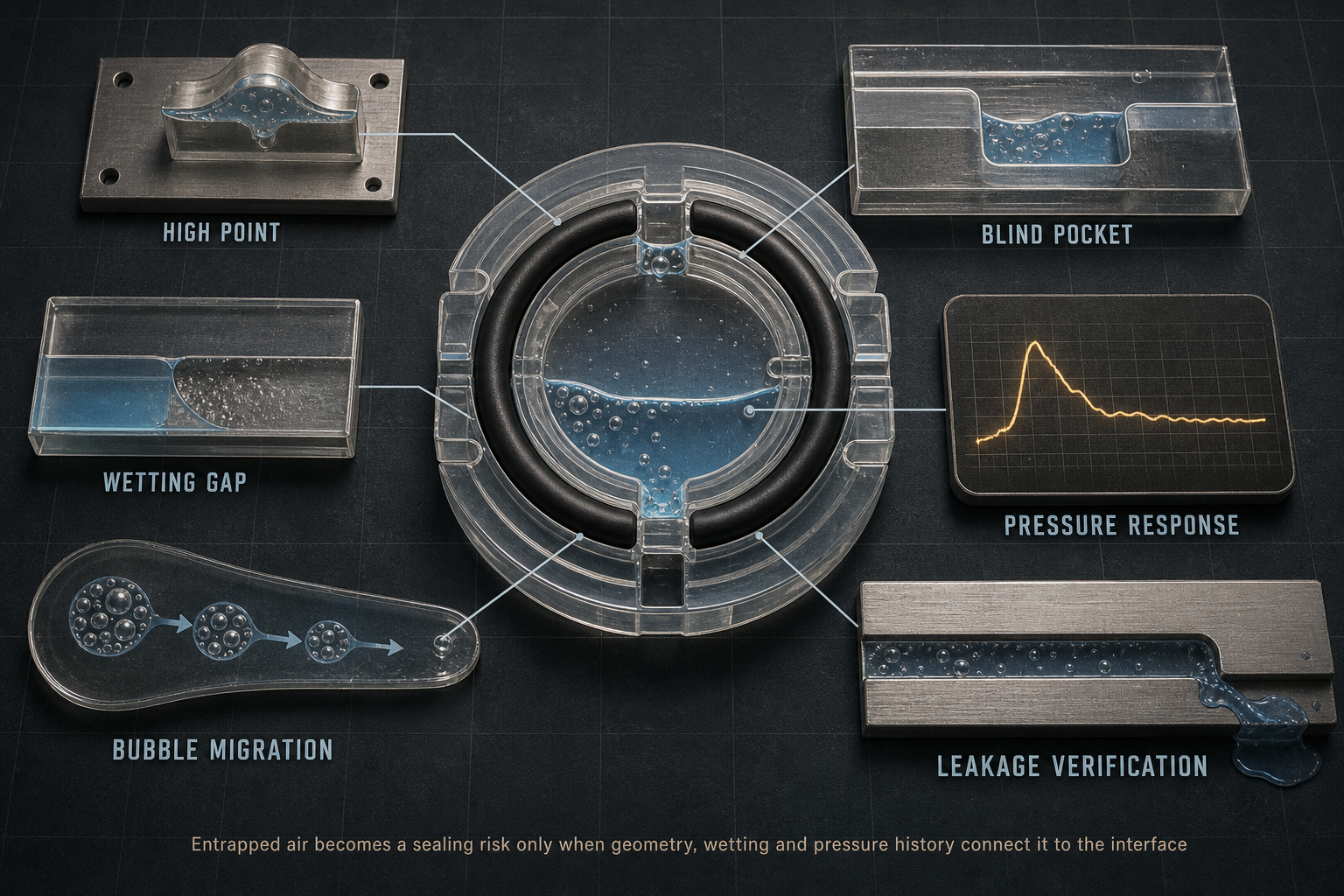
The sealing boundary is created jointly by the housing, cover, flange, groove, O-ring or gasket, seal chamber and connected fluid channel. Gas can survive wherever the structure creates a local high point, blind pocket, step, corner, surface-roughness valley or semi-closed volume after compression. These zones are not equivalent. Gas in a non-contact groove volume may mainly affect filling stability; gas near the seal-fluid interface may alter liquid-film continuity and local pressure transfer; gas connected to both pressure sides may become part of a true leakage path.
Flat gasket lands, radial O-ring grooves, electrolyzer end plates, liquid-cooling plates, valve bodies and vacuum chambers must not be treated as one geometry. A continuous groove may vent during progressive closure, while a blind groove may trap the final air pocket exactly when the cover reaches compression. A manifold corner may appear filled during static inspection but release gas only after pump start or valve switching. The design review therefore has to evaluate sealing, venting, drainage, filling direction and maintenance access as one coupled geometry, not as separate checklist items.
Table I: Gas-Retention Zones and Engineering Consequences
| Zone | Gas-entry route | Retention mechanism | System consequence | Verification focus |
| O-ring groove | Seal placement | Closed volume after compression | Unstable pressure response | Groove and vent review |
| Gasket land | Cover closure | Dry island under local load | Contact variation | Wetting trace |
| Blind pocket | Fast or incomplete filling | No direct escape route | Delayed gas release | Transparent test or teardown |
| High point | Purge limitation | Buoyancy-driven collection | False decay signal | Orientation and purge record |
| Valve cavity | Switching or refill | Dormant gas volume | Flow instability | Actuation-stage monitoring |
The same retained gas volume has different meaning depending on whether it is isolated, seal-adjacent or connected to the pressure boundary.
Assembly and Filling Air Entry
Most groove-related air problems are introduced before the system reaches its formal leakage test. Air can be sealed in during manual O-ring placement, gasket laydown, lubricant application, pipe connection, cover closure, progressive bolt tightening, pressure filling, vacuum filling or purge sequencing. The closure direction matters: a cover that closes from one side can sweep air toward the opposite high point; a cross-tightening pattern can divide one air pocket into several smaller pockets; immediate full compression can close the final escape route before liquid has displaced the gas.
The fluid then decides whether the remaining air can be displaced. High viscosity slows gas removal. High surface tension and poor wetting leave dry islands on metal, coating or elastomer surfaces. Contamination and excess lubricant can bridge corners and create sealed voids. Fast filling may wrap liquid around air and isolate it in the groove, while slow filling may still fail if the vent path is blocked or the dead zone is not hydraulically connected. Vacuum filling is useful only when the trapped volume communicates with the vacuum path and when the fluid does not introduce new vapor or gas-release effects. No fixed filling speed, vacuum duration or purge order can be generalized across groove geometries.
Table II: Filling, Wetting and Bubble-Risk Matrix
| Factor | Primary effect | Local interface risk | Required record | Main limitation |
| Fast filling | Air enclosure | Incomplete wetting | Fill sequence and pressure trend | Geometry dependent |
| High viscosity | Slow gas displacement | Long stabilization | Fluid temperature and viscosity | Fluid specific |
| Poor wetting | Film discontinuity | Dry contact zone | Surface condition | Not fully visual |
| Excess lubricant | Void bridging | Artificial pocket | Lubricant method | Operator dependent |
| Vacuum filling | Gas removal where connected | False confidence if isolated | Vacuum path and hold record | Does not prove wetting |
The matrix links controllable factors to mechanisms; it is not a universal set of process limits.
Wetting Loss and Contact Instability
Bubble retention is governed by surface tension, contact angle, local pressure, roughness, contamination, seal deformation and the geometry of the remaining void. A bubble may attach to a roughness valley, sit at a seal edge, remain in a high point, or occupy a region where lubricant residue prevents complete wetting. Under compression, the bubble may flatten rather than escape. That behavior matters because sealing performance depends not only on nominal compression but on whether the local interface is wetted, supported and pressure-stable.
Incomplete wetting can interrupt the liquid film and change how pressure is transmitted into the contact zone. In some geometries the gas remains harmless because it is isolated from the leakage path. In others it supports a temporary microchannel during pressure reversal, creates repeatability problems in pressure-decay testing, or migrates into a region where local contact pressure is already low. Bubble size alone is therefore a weak criterion. A small bubble in the wrong interface position can be more relevant than a larger bubble stored in a harmless dead volume. The engineering question is not whether a bubble exists; it is whether its location, mobility and connection to the pressure boundary can change the seal state.
Pressure and Thermal Cycling
A bubble trapped during assembly is not static. Pressure loading compresses gas and may temporarily hide its influence during a short hold test. Pressure release allows expansion and may move the gas toward a low-pressure region. Warm-up can reduce gas solubility, accelerate dissolved-gas breakout or promote vapor formation in susceptible fluids. Cooldown changes viscosity, wetting and gas dissolution. Dissolved gas is not visible entrapped air, but it can become a visible bubble after pressure or temperature conditions change.
Operational transients are equally important. Pump start, valve switching, flow acceleration, start-stop operation and thermal cycling can redistribute bubbles from dead zones into active channels or seal-adjacent pockets. Bubble collapse or rapid migration may produce noise, flow fluctuation or transient pressure response, but those observations do not prove seal damage. They must be separated from cavitation-like disturbance, liquid vaporization, material outgassing, permeation, external leakage, internal leakage and instrument response. A system that passes an initial pressure test may still contain gas that becomes diagnostically relevant after cycling.
Application-Specific Risk Patterns
Hydraulic and pneumatic seals usually emphasize pressure response, purge quality and flow stability; retained gas may compress and distort pressure-decay interpretation before any real external leakage is present. Liquid-cooling plates are more sensitive to high points, manifold corners and refill sequence; a bubble can reduce local heat-transfer stability or create flow noise without proving seal failure. Electrolyzer end-plate seals add stack compression, liquid partitioning and internal crossover risk, so local gas retention must be distinguished from true internal leakage between media zones.
Valve and manifold seals contain blind holes, spool cavities and switching volumes where gas may stay dormant until actuation. Vacuum-chamber seals require a different discipline: trapped gas, outgassing, permeation and true leak rate must be separated before assigning root cause. Pump, heat-exchanger and precision-fluidic seals add start-stop transients and narrow passages where small bubbles may create disproportionate diagnostic noise. These applications cannot share one air-removal rule. Each requires its own definition of the main boundary, gas-entry path, dead-zone location, suitable purge method and verification limit.
Leakage Diagnosis and Test Limits
Pressure decay is not a direct synonym for true leakage. It may result from gas compression, trapped-gas release, dissolved-gas breakout, temperature drift, test-system leakage, sensor error or actual fluid loss. Vacuum rate-of-rise may reflect retained gas, material outgassing, permeation, thermal change or a real leak. Visible bubbles may come from entrapped air, entrained gas carried by flow, dissolved gas leaving solution, vapor formation, air ingress through a leak or chemical gas generation.
A defensible leakage diagnosis combines methods rather than relying on one signal. Transparent fixtures can show visible bubbles but cannot cover opaque cavities. Pressure and vacuum decay tests require temperature and stabilization records. Flow monitoring must be interpreted with pump and valve state. Tracer gas can locate a leakage path but cannot prove complete liquid wetting. Teardown inspection should look for dry areas, wetting boundaries, gas marks, deposits, groove high points, seal imprint variation, contamination and assembly displacement. The required record includes filling sequence, vent condition, pressure, temperature, fluid viscosity, stabilization time and maintenance history.
Table III: Inspection and Leakage-Diagnosis Guide
| Method | Objective | Detectable issue | Best stage | Limitation |
| Visual observation | Locate visible gas | Large retained bubbles | Filling or transparent test | Opaque zones hidden |
| Pressure decay | Measure pressure loss | Leak or gas response | Commissioning | Not leakage-specific |
| Vacuum decay | Assess gas release | Leak, outgassing or retained gas | Pre-fill or vacuum service | Fluid state may differ |
| Flow trend | Find instability | Gas migration or pump effect | Operation | Multiple causes |
| Teardown | Confirm local evidence | Dry zones, deposits, imprint shift | Failure analysis | State may change during opening |
Diagnosis becomes credible only when the method matches the suspected location and failure mode.
Control Strategy and Maintenance Evidence
Control begins with geometry. Groove depth, width, corner form, continuity, high-point location, vent channel, purge path and drain path must allow air to leave before compression closes the interface. Excessive free volume can store gas; insufficient space can damage the seal or force rolling, twisting and extrusion. Neither condition can be judged by a universal groove width or compression value. The correct decision depends on seal cross-section, material, fluid, pressure, orientation and assembly process.
Maintenance must control the entire air-removal chain, not just replace the seal. The groove should be cleaned, burrs and deposits removed, seal identity and dimensions checked, lubricant quantity controlled, centering confirmed and the fill-and-vent sequence repeated. After refilling, records should capture purge order, stabilization time, pressure trend, flow behavior and any bubble observation. Clearing visible bubbles is not proof that all dead zones are deaerated, and one bubble-free run after rework is not evidence of long-term reliability under thermal and pressure cycling.
FMEA Risk Analysis
The FMEA focuses only on air retention, wetting instability and leakage-diagnosis errors related to sealing grooves. Its purpose is not to assign field statistics, but to identify where design, assembly and verification controls must be strengthened.
Table IV: Sealing-Groove Entrapped-Air FMEA and RPN Analysis
| Failure mode | Cause | Local effect | System effect | Detection | RPN | Corrective action |
| Inadequate vent path | Poor high-point access | Retained gas | False decay or delayed leak | Purge record | 168 | Revise vent route |
| Blind pocket | Closed geometry | Bubble hold-up | Intermittent instability | Transparent test | 144 | Remove pocket or change fill direction |
| Incomplete wetting | Residue or surface energy | Dry local zone | Contact variation | Teardown check | 126 | Clean surface and control lubricant |
| Seal misalignment | Assembly error | Uneven compression | Leak risk | Imprint check | 135 | Center seal and revise closure |
| False decay reading | Gas compression or temperature drift | Wrong root cause | Unnecessary rework | Repeat test | 108 | Separate thermal and leakage evidence |
| Weak requalification | Short retest | Hidden retained gas | Recurring instability | Cycle review | 150 | Document purge and retest sequence |
The RPN values are illustrative engineering risk rankings, not field statistics or experimental results.
Conclusion
Entrapped air and bubble retention in sealing grooves are governed by structure, closure sequence, wetting, filling, venting, purging and operating cycles. A bubble is not automatically a leak, but it can change local contact stability and test response in ways that resemble leakage. The correct engineering response is not to assign every pressure fluctuation or visible bubble to seal failure, but to trace the gas boundary, the fluid boundary and the verification boundary separately.
Reliable sealing practice requires distinguishing entrapped air, entrained gas, dissolved-gas breakout, outgassing, permeation, vaporization, cavitation, internal leakage, external leakage and test-system error. Only that separation allows engineers to decide whether the corrective action is groove redesign, vent-path improvement, filling-sequence control, surface cleaning, seal repositioning, material review or a more discriminating leak test.
Engineering FAQ
Q:Why does air become trapped in a sealing groove?
A:Because assembly closure, filling direction or groove geometry can isolate the last gas volume before liquid reaches a connected vent path.
Q:Can a trapped bubble directly cause seal leakage?
A:Only in some cases. It becomes a leakage concern when its position and connectivity disturb local contact or form part of a continuous leakage path.
Q:How are trapped air, entrained gas and dissolved gas different?
A:Trapped air is isolated in a cavity, entrained gas travels with the fluid, and dissolved gas remains in solution until pressure or temperature conditions cause breakout.
Q:Why can a system pass a pressure test but still contain trapped bubbles?
A:Pressure can compress retained gas and hide its effect during a short static test; later thermal or pressure cycling can make it expand, migrate or reappear.
Q:Does vacuum filling remove all air from a sealing interface?
A:No. It removes gas only where the pocket is connected to the vacuum path and where the fluid and materials do not introduce new gas or vapor effects.
Q:How should pressure decay from trapped gas be distinguished from true leakage?
A:Compare temperature, stabilization time, repeated pressure response, vacuum behavior, flow trend, visual evidence and independent leak-test results.
Q:What should be inspected after recurring bubble-related instability?
A:Inspect groove high points, blind pockets, vent paths, seal position, lubricant residue, contamination, fill sequence, pressure records and test-system integrity.
Post time: Sep-05-2026