
Executive Summary
EV battery enclosure sealing is a boundary-management problem, not a simple choice between a sealed or unsealed package. The tray, cover, flange, gasket, fasteners, special interfaces and vent components must control water and dust ingress while managing normal pressure change and abnormal gas release through engineered paths. Water protection, dust protection, pressure equalization and controlled thermal-runaway venting are related but non-interchangeable functions.
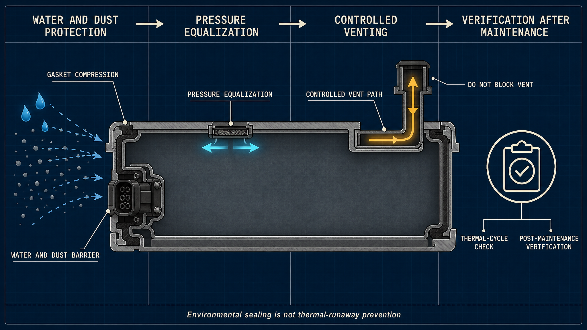
Normal sealing limits water, mud, cleaning fluid and particulate entry. A pressure-equalization feature manages routine pressure change, while a relief device or directed vent path addresses abnormal gas release. The gasket cannot prevent thermal runaway, and a fully closed enclosure is not automatically a safe pressure design. Vent opening, flow resistance, hot-gas routing and blockage tolerance require pack-level validation.
Reliability depends on joint geometry, compression, fastener load, thermal expansion, vibration, impact, chemical exposure and maintenance. A single water or enclosure leak test cannot prove long-term sealing or venting compatibility.
Battery Enclosure Sealing Architecture
A typical boundary includes a tray, cover flange, gasket groove, continuous gasket, fasteners and compression limiters. Separate interfaces surround cable glands, high-voltage connectors, coolant ports, service openings and vents. Each opening has its own tolerance stack; a sound perimeter gasket cannot compensate for a damaged connector seal.
The flange and cover define the joint, while the gasket converts fastener load into contact pressure. Groove shape, flatness, corners, splice locations and fastener spacing determine compression continuity. A pressure-equalization membrane may pass gas while resisting liquid and dust within its design conditions; a relief path serves an abnormal event. Map environmental sealing, equalization, controlled venting and inspection features separately so debris or maintenance cannot block an intended path.
Table I: Battery Enclosure Sealing Structure and Function
|
Component |
Sealing or safety function |
Main stressor |
Typical risk |
Verification focus |
| Tray and cover flange | Defines the joint boundary | Bending and thermal expansion | Local joint opening | Flatness and witness marks |
| Gasket groove and gasket | Maintains environmental contact | Compression variation and aging | Water or dust ingress | Seating and compression inspection |
| Fasteners and limiters | Applies and limits joint load | Relaxation and wrong sequence | Under- or over-compression | Process and load records |
| Connector and coolant interfaces | Seals local openings | Misalignment and contamination | Local fluid path | Interface leak test |
| Vent membrane or relief path | Manages normal or abnormal gas flow | Blockage and damage | Pressure-management failure | Flow-path inspection |
This structure separates perimeter sealing from special openings and gas-management components. Each function needs its own tolerance and verification evidence.
Gasket Compression and Joint Integrity
Gasket sealing requires sufficient local contact pressure and continuous surface conformity. Compression ratio, flange flatness, surface cleanliness, fastener spacing, bolt sequence and enclosure stiffness all affect the result. Under-compression can leave a local leakage path; over-compression can damage the gasket, restrict intended movement, accelerate compression set or create extrusion. A compression limiter may control joint closure, but it does not correct a warped flange or an incorrect assembly sequence.
Fasteners should follow the defined design and manufacturing process, not a universal torque assumption. Staged tightening may reduce distortion, but the suitable sequence depends on the enclosure. Particles, residue, corrosion and gasket misplacement can create a leak even when the recorded operation appears correct.
A completed joint is not proof of uniform sealing. Inspect seating, corners, splices, witness marks, flange damage and contamination. Compression, torque and leakage limits must be confirmed for the specific gasket, enclosure, temperature, pressure and process.
Water, Dust and Chemical Exposure
Road spray, immersion, condensation, dust, mud, salt and cleaning fluid challenge the enclosure differently. Pressure washing can impose a local load; salt and mud can remain at flange edges; condensation can expose the internal boundary without visible external water. Coolant or electrolyte contamination may change gasket volume, hardness, friction or adhesion and attack coatings or connector materials.
Exposure can cause swelling, hardening, softening, cracking, compression-set growth, surface damage or contact-pressure loss. Trapped particles hold the gasket away from the flange, while corrosion changes the surface and leakage path. Evaluate water and dust protection with the intended exposure, orientation, drainage and inspection method; no universal test value should be assumed.
Table II: Water, Dust, Thermal and Mechanical Influence Matrix
|
Stress factor |
Primary effect |
Secondary effect |
Potential failure mode |
Required measurement |
Main limitation |
| Water or immersion | Fluid reaches joint | Corrosion or swelling | Water ingress | Exposure and leak inspection | Orientation dependent |
| Dust or mud | Particles enter interface | Local contact loss | Dust ingress | Visual and cleanliness check | Particle distribution varies |
| Thermal cycling | Compression changes | Stress relaxation | Thermal-cycle leakage | Temperature and leak record | Pack-specific history |
| Vibration or shock | Gasket movement | Fastener-load loss | Vibration-induced leakage | Vibration and teardown | Vehicle input varies |
| Coolant or electrolyte | Chemical interaction | Surface degradation | Interface leakage | Compatibility and inspection | Fluid composition matters |
The matrix prevents one exposure result from being treated as proof against every environmental or mechanical stress.
Thermal Cycling, Vibration and Enclosure Deformation
The enclosure, gasket and fasteners may expand differently. Heating and cooling change flange separation, compression and contact pressure; gradients can bend the cover or tray. Charging cycles, vibration, shock and road load can reduce fastener load, move the gasket or enlarge a surface defect.
Thermal-cycle passage does not prove long-term water resistance, and static water testing does not replace vibration or shock testing. Interpret results with temperature history, restraint, fastener condition, witness marks and post-test inspection.
Pressure Equalization and Thermal-Runaway Venting Compatibility
This distinction is central. The enclosure gasket limits external environmental ingress. A pressure-equalization feature manages routine internal pressure change caused by temperature or altitude variation. A controlled venting system provides a designed route for abnormal gas release. These functions cannot be replaced by one gasket or by simply making the enclosure more airtight.
A vent membrane, pressure-relief device or directed path must be evaluated for flow direction, resistance, contamination, mounting and blockage tolerance. Gasket material, sealant, debris, deformation or service hardware must not block it. The environmental gasket is not the primary thermal-runaway relief device; over-closure can create pressure risk, while a damaged vent can create water-ingress risk.
Thermal-runaway gas release requires a complete pack safety concept covering routing, vent location, surrounding components and vehicle-level protection. No universal vent pressure, temperature or flow rate is assigned here. Pack-level validation defines the boundary. A seal supports environmental protection; it cannot stop thermal runaway or guarantee safety in every accident condition.
Table III: Battery-Pack Sealing and Venting Verification Guide
|
Test or inspection |
Test purpose |
Key variable |
Detectable issue |
Suitable stage |
Main limitation |
| Visual and compression inspection | Confirm joint condition | Seating, witness marks | Misplacement or damage | Assembly and service | Surface evidence only |
| Water or immersion test | Check ingress resistance | Exposure and internal evidence | Water path | Design and validation | Does not test vent safety |
| Dust-ingress test | Check particulate protection | Dust exposure and residue | Dust path | Design and validation | Setup dependent |
| Pressure-equalization test | Check normal gas path | Flow response and blockage | Equalization failure | Design and service | Not thermal-runaway validation |
| Thermal and vibration test | Assess durability | Cycles, input and leakage | Progressive leakage | Qualification | Requires representative input |
| Vent-path inspection | Confirm abnormal path availability | Opening and resistance | Blockage or damage | Assembly and maintenance | Pack-level event test remains separate |
Each method answers a different question. Environmental sealing, normal pressure management and abnormal gas release must remain separate verification claims.
Material Selection and Interface Compatibility
EPDM, silicone rubber, FKM, FVMQ, foam, molded, dispensed-in-place, compression and adhesive-backed gaskets may suit different designs. Selection must consider temperature, compression set, water and dust, coolant and chemical compatibility, vibration, reworkability, tolerance capability, particles and the vent interface.
Temperature rating alone is insufficient. A gasket may resist one fluid but swell in another; a soft profile may conform well but lose compression stability; a molded profile may improve repeatability but require tighter groove control. Hot-gas exposure is a separate boundary and cannot be inferred from routine environmental compatibility.
Inspection, Testing and Maintenance
Inspection should combine visual, dimensional, functional and record evidence. Check gasket seating, groove, flange flatness, fastener process, connector and coolant interfaces, and vent components before closure. Water, immersion and dust tests examine environmental protection; pressure-equalization tests examine the normal path; thermal, vibration and shock tests examine durability. None alone proves abnormal-event venting safety.
After maintenance, clean the enclosure, inspect interfaces, repeat the defined assembly sequence and verify the perimeter plus each opening. Record materials, geometry, compression, vent design, pressure result, environmental result, history, action and findings. Teardown should look for compression set, displacement, tearing, corrosion, contamination and blockage.
Data Interpretation and Maintenance Planning
Maintenance decisions should distinguish external water ingress, boundary leakage, pressure-equalization abnormality and vent damage. Post-impact or post-flood inspection may be justified without visible water because contamination and hidden gasket displacement can remain. Condition-based maintenance may use history and trends, but a laboratory result must not become a fixed vehicle life.
After gasket replacement or pack disassembly, requalify the post-maintenance state under representative conditions. The objective is to show that environmental sealing, special interfaces and pressure-management paths have returned to their defined condition.
FMEA Risk Analysis
The RPN values are illustrative engineering risk rankings, not field statistics or experimental results.
Table IV: EV Battery Enclosure Sealing FMEA and RPN Analysis
|
Failure mode |
Cause |
Local effect |
System effect |
Detection method |
RPN |
Corrective action |
| Gasket under-compression | Tolerance stack or wrong assembly | Local contact loss | Water or dust ingress | Compression and leak inspection | 240 | Control joint geometry and assembly verification |
| Gasket compression set | Aging and heat exposure | Reduced recovery force | Thermal-cycle leakage | Teardown and repeat environmental test | 210 | Review material and replacement interval |
| Flange distortion | Impact or joint overloading | Uneven contact | Persistent perimeter leak | Flatness and witness-mark inspection | 216 | Correct flange condition and joint load |
| Vent-path blockage | Debris, sealant or deformation | Increased flow resistance | Pressure-management failure | Vent-path inspection and functional test | 280 | Protect, clean and verify the path |
| Vent-component damage | Impact or incorrect service | Open or restricted vent path | Water ingress or abnormal release path | Visual and functional inspection | 252 | Replace component and requalify |
| Connector-interface leakage | Seal damage or misalignment | Local fluid path | Electrical isolation risk | Connector leak test and inspection | 245 | Replace interface seal and verify fit |
| Vibration-induced movement | Road load or fastener-load loss | Gasket displacement | Progressive ingress | Vibration test and teardown | 224 | Improve retention and post-test inspection |
The FMEA separates gasket, flange, vent, connector and maintenance risks because they require different controls. A high ranking does not prove field frequency; it indicates where detection and corrective action deserve engineering attention.
Conclusion
EV battery enclosure sealing is a coordinated boundary system. Gasket compression, flange integrity, fastener load and special interfaces control water and dust ingress, while pressure equalization and thermal-runaway venting have different purposes and validation requirements. The enclosure is not an absolutely closed volume, and the gasket is not a thermal-runaway safety device.
Verification combines environmental exposure, pressure-path checks, thermal cycling, vibration, shock, interface inspection and post-maintenance requalification. Decisions must follow the specific enclosure, gasket, vent design, vehicle condition and safety validation, not a universal compression value, leakage limit or material claim.
Engineering FAQ
Q:How does an EV battery enclosure gasket prevent water and dust ingress?
A:It maintains contact between the cover and base flange across the defined joint. Actual performance depends on continuous compression, flange condition, fastener load, surface cleanliness, special openings and exposure conditions.
Q:Why can a battery pack pass a water test but still develop long-term leakage?
A:A single test may not reproduce thermal cycling, vibration, impact, contamination, compression set or maintenance damage. Long-term assessment requires representative durability and post-test inspection.
Q:How should enclosure sealing be coordinated with pressure equalization?
A:The gasket should limit environmental ingress while the pressure-equalization feature manages normal pressure change. Their locations, flow resistance, contamination protection and service conditions must be evaluated together without blocking the intended path.
Q:Can a fully sealed battery enclosure safely manage thermal-runaway gases?
A:Not by sealing alone. Abnormal gas release requires a pack-level controlled venting and protection concept. The gasket cannot prevent thermal runaway, and a sealed enclosure must not obstruct the validated relief path.
Q:What should be inspected after battery-pack maintenance or impact?
A:Inspect gasket seating, compression witness marks, flange flatness, fastener process, connector and coolant interfaces, vent components, contamination and any deformation. Repeat defined environmental and pressure-path checks before return to service.
Q:Which tests are needed to verify gasket sealing and vent-path compatibility?
A:Use the tests required by the specific design: water, dust, pressure-equalization, thermal-cycle, vibration, shock, interface and post-maintenance checks. Environmental sealing results must not be treated as thermal-runaway venting validation.
Post time: Aug-29-2026