
Executive Summary
EV thermal-management valves separate or switch refrigerant, glycol-water coolant, air-side conditions and residual process fluids. Their sealing reliability is a boundary-condition problem rather than a material-name problem. Refrigerant compatibility, glycol compatibility, seal geometry, valve motion, pressure and temperature cycling, switching transients, assembly quality and leakage verification must be considered together. A static gasket, dynamic stem seal and valve-seat interface can experience different media, contact pressures and motion histories within one valve.
Refrigerant leakage, glycol leakage and external air ingress are different observations. Permeation and diffusion can occur without a visible flow path, while swelling, shrinkage, hardening, softening and compression-set loss can change contact pressure. A single-medium immersion, one temperature condition or one static leak test cannot represent long-term reliability after refrigerant-to-glycol switching. Validation must reproduce media sequence, pressure state, temperature history, valve movement and post-maintenance condition.
Thermal-Management Valve Architecture
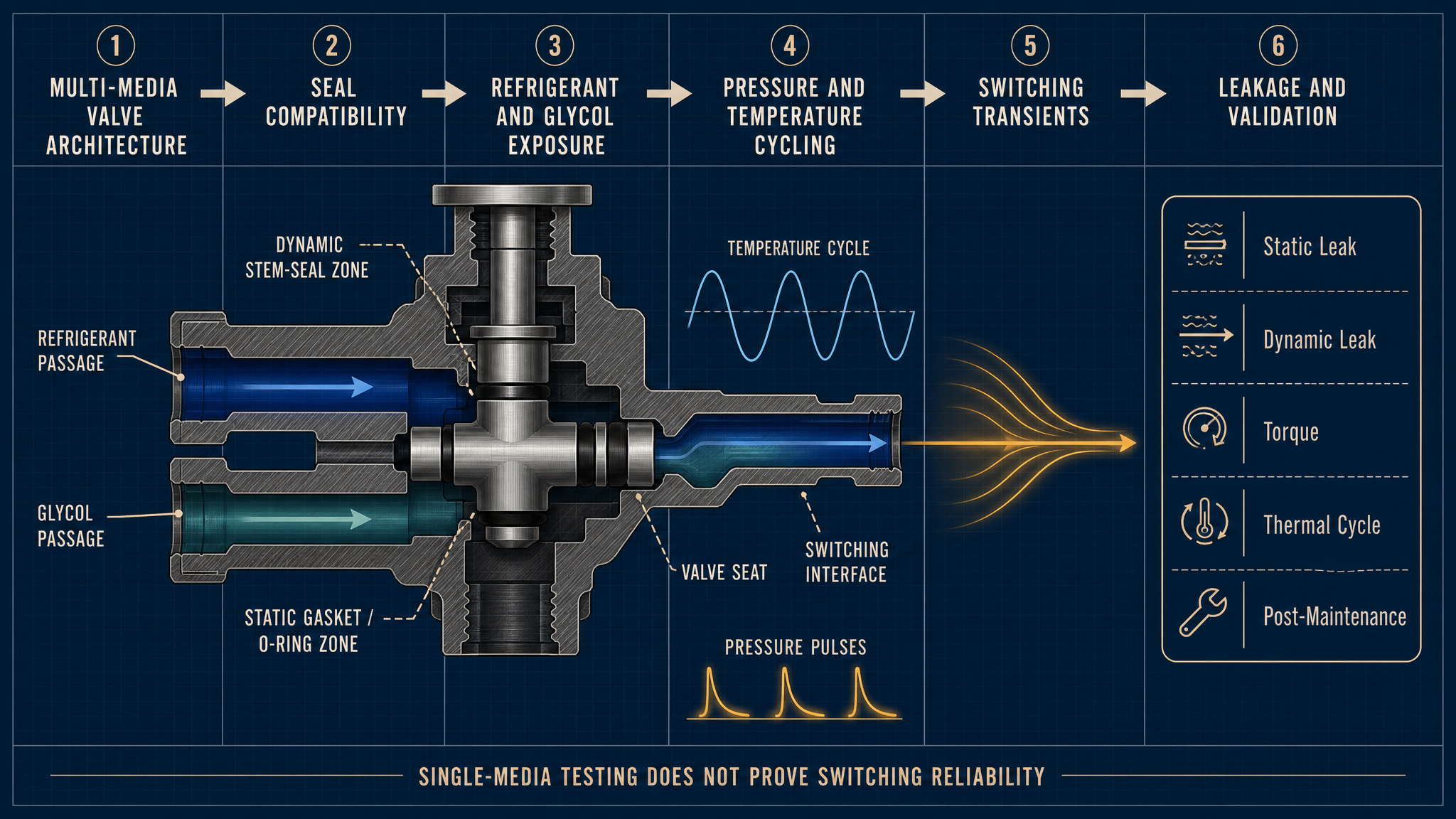
A thermal-management valve contains a body, stem, plug or spool, seat, actuator and flow passages. Static gaskets and O-rings seal fixed joints between the body, cover and cartridge. A dynamic stem seal manages reciprocating or rotary motion, so friction, wear, stem finish and alignment become part of the sealing boundary. A lip seal may use directional contact to retain fluid, whereas a valve-seat seal must close a passage and tolerate pressure differential, particles and repeated seating.
The seal groove controls squeeze, support and extrusion resistance. The refrigerant passage may expose a seal to pressure variation and permeation; the glycol passage may introduce water, glycol, inhibitors, moisture and additives. At the switching interface, one seal can be wetted by different media. The actuator adds load variation, while stem eccentricity, plug offset, seat wear and assembly error can create intermittent leakage.
Table I: Thermal-Management Valve Sealing Functions and Risks
|
Valve or seal component |
Main function |
Media exposure |
Typical risk |
Verification focus |
| Valve body joint | Fixed boundary | Refrigerant, glycol, air | Gasket relaxation, extrusion | Static leak and joint inspection |
| Valve-stem seal | Dynamic barrier | Selected media and residue | Wear, friction, stem leakage | Dynamic leak and torque trend |
| Valve seat | Flow-path isolation | Pressure-side media | Seat wear, particle interference | Seat closure and pressure test |
| O-ring and groove | Fixed or cartridge sealing | Media, moisture, additives | Swelling, shrinkage, set loss | Dimension and groove inspection |
| Switching interface | Separates media paths | Alternating media | Residue, mixing, transient leak | Sequence test and teardown |
Judge each component by exposure and movement, not by its label. A stem seal can pass a static check yet fail during movement, while a seat can pass a low-pressure check yet leak after pressure pulses or thermal distortion.
Refrigerant and Glycol Compatibility
Refrigerants and glycol coolants influence sealing materials through different pathways. Refrigerant exposure may involve pressure-driven permeation, diffusion, temperature-dependent response and rapid fluid-state changes. Glycol coolant exposure may involve water, glycol, corrosion inhibitors, stabilizers, contamination and material extraction. Moisture and residual process fluid can change interface chemistry even when the nominal medium is known.
Possible responses include swelling, shrinkage, hardening, softening and compression-set development. Swelling can increase friction or reduce clearance; shrinkage can lower contact pressure. Hardening may reduce low-temperature compliance, while softening can increase extrusion or wear. These responses depend on formulation, temperature, pressure, exposure time, geometry and mechanical constraint.
No single material should be treated as a universal solution. EPDM, FKM, HNBR, FVMQ, PTFE-based elements, PEEK or other engineered polymers must be assessed against the actual media, additives, temperature, pressure and motion. Screening is necessary, but it does not replace testing the assembled valve.
Pressure, Temperature and Valve-Motion Effects
Pressure differential loads the seat, stem seal and static boundaries differently. Pressure cycling repeatedly changes contact stress and can expose extrusion weaknesses hidden in a static condition. Pressure-pulse damage may appear as indentation, seal-edge displacement or progressive seat leakage rather than immediate failure.
Thermal cycling changes modulus, dimensions, lubricant behavior and compression recovery. Low-temperature start can increase friction and reduce compliance, while high-temperature operation can accelerate softening, relaxation, additive interaction or permeation. Valve stroke, rotation, speed and seating velocity add frictional heat and wear. Increased torque may indicate swelling, changed wetting, stem damage, misalignment, seat interference or degraded lubrication; it should not automatically be assigned to incompatibility.
A pressure test does not prove dynamic sealing. One temperature, pressure, torque or cycle count is not a universal standard. The record must connect leakage or torque change to the valve architecture and operating sequence.
Table II: Refrigerant, Glycol and Switching Influence Matrix
|
Stress factor |
Primary effect |
Secondary effect |
Potential failure mode |
Required measurement |
Main limitation |
| Refrigerant exposure | Permeation or material response | Contact-pressure change | Refrigerant leakage | Mass or pressure loss, leak location | Does not represent glycol switching |
| Glycol and additives | Swelling, extraction or hardening | Friction and set change | Glycol leakage, torque rise | Fluid condition, dimensions, torque | Formulation-specific |
| Pressure cycling | Repeated contact loading | Extrusion or seat damage | Pressure-pulse damage | Pressure history and leak trend | May miss motion-related wear |
| Thermal cycling | Modulus and dimension change | Compression relaxation | Thermal-cycle leakage | Temperature history and post-test leak | Does not isolate chemistry |
| Media switching | Wetting and lubrication change | Residual-fluid interaction | Switching-induced leakage | Sequence, dwell, pressure and leak | Requires representative sequence |
| Valve motion | Sliding or rotating wear | Heat and debris generation | Stem leakage, seat wear | Stroke, torque and surface track | Static tests cannot replace it |
The matrix is a planning tool. It does not replace a design-specific test definition with identified media, geometry and boundary conditions.
Multi-Media Switching and Interface Risk
The critical risk in a multi-media valve is the transition. During refrigerant-to-glycol switching, residual fluid can remain in a groove, seat or stem. Pressure equalization may occur while the seal is wetted by the previous medium. A rapid temperature change can alter viscosity, swelling, friction and contact pressure. The next medium may therefore encounter a surface unlike a clean single-medium condition.
Media mixing can create interface contamination without an obvious material failure. A residual inhibitor, process solvent or previous coolant may change wetting, lubrication or material extraction. Cross-contamination between circuits can make diagnosis ambiguous: a measured fluid may be a mixture, trace residue or cleaning fluid rather than the nominal service medium.
Switching fatigue is not only a cycle-count issue. A media-switching transient combines sequence order, pressure differential, temperature, dwell time, valve speed and equalization. The pressure-pulse effect should be evaluated within that sequence. Validate representative boundaries; a material selected for one refrigerant or glycol coolant cannot automatically suit every switching sequence.
Material and Interface Selection
Material selection should follow geometry and interface design. EPDM may be considered for glycol-coolant exposure and low-temperature flexibility, subject to formulation and temperature history. FKM may offer useful high-temperature or chemical-resistance characteristics in selected refrigerant environments, but low-temperature behavior must be confirmed. HNBR can be evaluated where mechanical strength and fluid resistance are both required. FVMQ may suit selected low-temperature or gas-exposure conditions, with attention to mechanical limits.
PTFE-based elements can reduce friction or provide chemical resistance in suitable geometries, but require support and control of cold flow. PEEK and other engineered polymers may serve as guide, seat or support components rather than universal elastomer replacements. Coated stems and metal seats reduce wear risk only when coating integrity, surface condition, alignment and counterface behavior are controlled. Filled polymers add variables in filler type, orientation and surface interaction.
Every material option is conditional. A compatibility chart cannot predict the combined effect of pressure pulses, thermal cycling, valve motion, residual media and assembly variation on an installed valve.
Inspection, Testing and Maintenance
Verification should combine chemistry, mechanics and leakage measurement. Static testing checks fixed boundaries and closed seats; dynamic testing examines stroke or rotation. Separate refrigerant-side and glycol-side pressure tests so leakage identity is clear. Switching tests reproduce sequence, equalization, temperature transitions and dwell conditions that change wetting and friction.
Thermal-cycle testing identifies leakage after modulus and dimensions change. Pressure-cycle testing examines repeated load and pulse effects. Torque monitoring can reveal swelling, wear, contamination or misalignment before leakage is obvious. Inspection should include seat condition, stem surface, seal dimensions, groove support and installation direction. Teardown should record swelling, hardening, compression set, indentation, extrusion, wear tracks and residual media.
A refrigerant test does not replace a glycol test. Glycol immersion does not replace switching verification. Static leakage does not replace dynamic action. One pressure test does not prove long-term reliability. After maintenance, the replacement material, geometry, orientation, squeeze, lubrication state and valve action should be checked before the valve returns to service.
Table III: EV Thermal-Management Valve Seal Verification Guide
|
Test or inspection |
Test purpose |
Key variable |
Detectable issue |
Suitable stage |
Main limitation |
| Static leakage test | Check fixed or closed boundaries | Pressure, temperature, duration | Seat or body leakage | Production and validation | No valve motion |
| Dynamic leakage test | Check sealing during movement | Stroke, speed, torque | Stem leakage, wear | Design validation | Requires controlled actuation |
| Media-side pressure test | Separate fluid-path behavior | Refrigerant or glycol side | Path-specific leakage | Validation and service | Medium-specific |
| Switching test | Reproduce transition risk | Sequence, dwell, pressure | Residue and transient leakage | System validation | Sequence must be representative |
| Thermal and pressure cycling | Expose repeated boundary changes | Temperature and pressure history | Set loss, extrusion, pulse damage | Reliability validation | Does not identify one cause alone |
| Teardown and dimension check | Identify morphology and change | Seal size, surface, hardness | Swelling, wear, set, residue | Failure analysis and service | Destructive and local |
Each result should retain valve identity, material record, media condition, pressure and temperature history, switching sequence, torque trace, leakage result and teardown observations.
Data Interpretation and Maintenance Planning
A useful record connects valve type and architecture with seal material, geometry, refrigerant, glycol coolant, additive package, pressure, temperature, switching sequence, actuation torque, leakage result, thermal history, seal dimensions, surface condition and corrective action. This prevents a mixed-fluid observation from being misclassified as a simple material failure.
Maintenance may be calendar-based, mileage-based, operating-cycle-based, leakage-trend-based, torque-trend-based, condition-based or risk-based. The appropriate trigger depends on valve duty and available monitoring. Post-repair requalification should confirm material identity, installation direction, compression state, valve movement and relevant media-side leakage. Laboratory immersion duration or action count should not be converted directly into a universal vehicle life.
FMEA Risk Analysis
Table IV: EV Thermal-Management Valve Sealing FMEA and RPN Analysis
|
Failure mode |
Cause |
Local/System effect |
Detection method |
RPN |
Corrective action |
| Refrigerant incompatibility | Seal chemistry not matched to exposure | Permeation or swelling; refrigerant leakage | Media test, leak localization | 180 | Review compatibility and validate assembly |
| Glycol incompatibility | Coolant or additive interaction | Softening or hardening; glycol leakage | Fluid analysis, teardown | 168 | Confirm formulation and material screening |
| Compression-set loss | Heat, time or excessive squeeze | Reduced contact; static leakage | Dimension and recovery check | 150 | Rebalance groove and thermal design |
| Stem-seal wear | Motion, rough stem or debris | Wear track; dynamic leakage | Torque trend and surface inspection | 192 | Control finish, alignment and cleanliness |
| Valve-seat wear | Particles, misalignment or pulse load | Incomplete isolation; cross-path leakage | Seat inspection and pressure test | 210 | Improve seat support and particle control |
| Switching-induced leakage | Residue, wetting or pressure transient | Temporary or progressive leakage | Sequence test and fluid identification | 216 | Validate actual switching order and equalization |
| Thermal-cycle leakage | Modulus and dimension variation | Loss of contact after cycling | Thermal cycle plus leak test | 175 | Review low/high-temperature contact margin |
| Incorrect seal installation | Wrong material, direction or squeeze | Immediate or delayed leakage | Work instruction and post-repair test | 225 | Add traceability, visual checks and requalification |
| Incomplete post-maintenance verification | Static-only release decision | Dynamic or media-specific defect remains | Audit records and repeat tests | 240 | Require static, dynamic and relevant media checks |
The RPN values are illustrative engineering risk rankings, not field statistics or experimental results. They prioritize review; they do not replace design evidence or failure analysis.
Conclusion
EV thermal-management valve sealing is governed by the complete interface between refrigerants, glycol coolants, seal geometry, valve motion, pressure and temperature cycling, switching transients and maintenance quality. Refrigerant leakage, glycol leakage, air ingress, permeation, diffusion and compression-set loss describe different physical observations and require different diagnostic methods.
A reliable program separates static, dynamic, seat and stem-seal behavior; evaluates material compatibility against actual media and additives; reproduces switching order and pressure-temperature history; monitors torque and leakage; and inspects the seal and interfaces after testing. No single material, seat design or valve architecture eliminates all switching risk. Reliability is established by representative validation and post-maintenance verification.
Engineering FAQ
Q:How do refrigerants and glycol coolants affect valve seals differently?
A:Refrigerants can drive permeation, diffusion and pressure-dependent material response, while glycol coolants expose seals to water, glycol, inhibitors, additives and possible contamination. The resulting swelling, shrinkage, hardening or softening depends on formulation and temperature, so separate media-side testing is required.
Q:Why can a valve pass a single-media leak test but fail after media switching?
A:Switching changes wetting, lubrication, residual-fluid chemistry, pressure equalization and temperature state. A seal that performs in a clean single-medium condition may experience altered friction or contact pressure when the previous medium remains at the interface.
Q:How does thermal cycling change thermal-management valve sealing?
A:Thermal cycling changes material modulus, dimensions, viscosity and compression recovery. These changes can reduce contact pressure, increase friction or expose extrusion and seat-alignment weaknesses that are not visible at one temperature.
Q:What causes increased actuation torque in a multi-media valve?
A:Possible causes include swelling, hardening, changed lubrication, residual-media contamination, stem-surface damage, seat interference, misalignment and thermal distortion. Torque should be interpreted with leakage, temperature history and surface inspection rather than assigned to one cause automatically.
Q:Which tests are needed after replacing a thermal-management valve seal?
A:Confirm material identity, geometry, orientation, groove condition and compression first. Then perform the applicable static and dynamic leakage checks, relevant refrigerant and glycol-side checks, actuation verification and any required switching or thermal requalification before release.
Q:Can one sealing material suit every refrigerant and glycol application?
A:No universal selection should be assumed. Compatibility depends on the actual refrigerant, glycol formulation, additives, temperature, pressure, geometry, motion, surface condition and switching sequence. Material screening must be followed by assembled-valve validation.
Post time: Aug-31-2026