
Executive Summary: Surface Damage Precedes Many Vacuum Failures
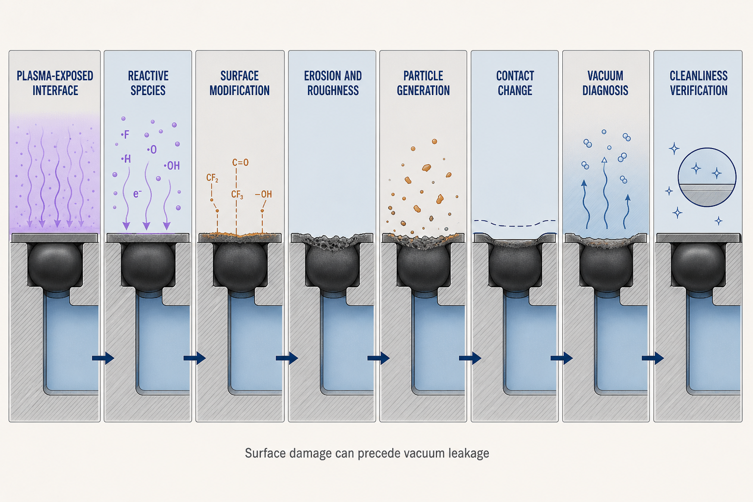
FFKM surface erosion in a plasma chamber is not simply a question of whether the polymer survives a nominal temperature. The exposed surface receives a chemically specific combination of radicals, ions, ultraviolet radiation, heat and process by-products. That combination can change the outer layer while the compressed bulk still maintains contact. Consequently, the first measurable effect may be roughness, pitting, hardening, mass loss, powdering or particle release rather than a failed helium leak test.
Particle risk can rise before macroscopic leakage, while vacuum pressure can rise from outgassing, volatile products, residues, contamination or temperature change. These alternatives must be separated from true leakage. Initial helium tightness, static temperature exposure or one plasma run is only a starting condition.
A defensible evaluation maps exposure zones, identifies active species, characterizes surface modification, connects morphology to particles and contact stability, and verifies vacuum behavior after representative plasma and cleaning cycles. Conclusions must state the compound, geometry, exposure location and test method.
Chamber Architecture: Exposure, Contact and Particle Boundaries
A chamber lid, flange and groove separate the plasma-side vacuum from atmosphere. The FFKM O-ring is not exposed uniformly: its edge may see species and radiation, the shoulder may be shadowed, and the compressed band may remain sensitive to heat, deposits and stress. Treating the cross-section as uniform hides damage origin.
Groove depth, alignment, contact width, clearance and edge radius determine species access and contact margin after recession. A shield can reduce direct exposure but create an edge transition with changing chemistry, temperature and deposition. A small damaged zone matters if it faces vacuum or a particle path to a wafer, window, sensor or pump.
The architecture supplies two boundaries: loss of contact becomes a vacuum path, while a detached fragment enters a particle-sensitive region. Table I separates exposed, edge, shadowed and contact surfaces for inspection.
Table I. Plasma-Chamber FFKM Sealing Zones and Functions
| Seal zone | Exposure condition | Main sealing function | Typical surface risk | Contamination risk | Verification focus |
| Plasma-facing surface | Direct reactive exposure | Vacuum isolation | Erosion and roughening | Particle shedding | Morphology and chemistry |
| Edge zone | Species and heat gradient | Contact continuity | Recession and pitting | Localized debris | Microscopy and dimensions |
| Shadowed zone | Partial shielding | Seal protection | Deposition or thermal change | Residue release | Surface comparison |
| Contact zone | Compressed and shielded | Leak-path closure | Set or rubbing damage | Assembly debris | Compression and leak test |
| Groove interface | Housing and clearance | Restraint | Cutting, extrusion or contamination | Handling particles | Groove and flange inspection |
Reactive Species, Surface Chemistry and the Start of Erosion
Plasma chemistry determines which surface reactions are possible. Fluorine-, oxygen-, chlorine- and hydrogen-containing species can produce different balances of bond attack, volatile products, non-volatile residues and surface restructuring. Radicals primarily drive chemical reaction, ions add momentum and energy, and ultraviolet radiation can alter bonds or accelerate secondary reactions. Calling all of these effects “high-temperature corrosion” removes the information needed to control them.
Reaction is spatially non-uniform: direct, edge and shadowed zones receive different species fluxes and energy. Gas mixture, pressure, power, density, temperature, angle, chamber condition and cleaning history can change the pathway without changing the FFKM designation. A deposit may protect one region, then flake later.
A material label cannot predict one universal erosion rate or particle output. Compare exposed and protected areas under a recorded process history. Interpret surface chemistry with morphology: a changed bonding signal may indicate modification, while roughness without chemical evidence may reflect rubbing, deposit removal or preparation.
Table II. Plasma Exposure, Surface Erosion and Particle-Risk Matrix
| Operating factor | Primary effect | Secondary effect | Potential failure mode | Required measurement | Main limitation |
| Gas chemistry | Surface reaction | Volatile or fixed residue | Erosion or deposition | Gas and process record | Chemistry-specific |
| Ion and UV energy | Bond and momentum transfer | Roughening or embrittlement | Pitting or cracking | Energy proxy and morphology | Hard to isolate |
| Surface temperature | Reaction and modulus change | Recovery loss or aging | Leakage or particles | Surface temperature history | Sensor may differ |
| Cycle history | Repeated exposure | Cumulative damage | Powdering or delayed leak | Plasma and clean cycles | No universal life rule |
| Compression and shielding | Contact and access control | Edge stress or residue | Leakage or shedding | Geometry and assembly check | Equipment-specific |
| By-product deposition | Surface masking | Flaking or transport | Particle contamination | Chemistry and microscopy | May mimic erosion |
Erosion Morphology, Particle Release and Seal Integrity
Surface erosion is a form of surface modification involving removal, restructuring or chemical alteration of the outer layer by reactive species or deposited energy. The visible forms can include roughening, pits, microvoids, microcracks, edge recession, exposed filler, additive depletion, hardening and embrittlement. These forms are not interchangeable. A rough surface may still seal, while a narrow crack at the vacuum-facing edge can create a leak path even when the rest of the ring looks intact.
Particle generation depends on the altered layer’s mechanical state. A weakened layer may remain attached, then detach during cooling, venting, rubbing or cleaning. Filler exposure can change fracture paths; residue can cover damage and later peel. A clean appearance therefore does not exclude sub-visible particles.
Geometry determines the consequence of a given erosion depth. Loss at a broad, shielded band may reduce recovery gradually; loss at an edge or narrow contact line can sharply reduce sealing margin. Compression, groove fill, alignment and thermal expansion decide whether the damaged surface conforms or opens a channel. Separate this from compression set, extrusion, installation cutting and chemical swelling.
Particles must be traced, not merely counted. FFKM fragments, filler release, process deposits, cleaning residue, rubbing debris and external contamination differ in chemistry and morphology. Trends require sampling location, chamber state, pump condition, process history and source identification.
Thermal Exposure, Vacuum State and Repeated Plasma Cycles
Seal surface temperature may differ from chamber or instrument readings because of ion energy, radiation, metal conduction and contact resistance. Plasma cycling changes chemistry, modulus and recovery; pump-down and venting add pressure transitions; cleaning may be more aggressive than the main process. A chemically altered layer may embrittle during thermal cycling or release residue during contact movement.
Vacuum pressure response must be interpreted in the same time sequence as the process. A pressure rise that follows heating may reflect desorption or volatile products; a rise that persists after thermal stabilization may require leak-path investigation; a change after cleaning may reflect residue, chamber condition or seal damage. Temperature, waiting time, pumping state and chamber cleanliness must therefore be recorded before assigning the symptom to leakage.
Service-life verification should reproduce plasma chemistry, exposure position, thermal history, cleaning and maintenance state. Report it as a defined-condition comparison, not a universal cycle count. High-temperature testing without plasma species cannot establish erosion resistance.
Diagnosis, Cleaning and Post-Maintenance Verification
Helium testing locates certain through-paths but does not measure particles, chemistry or future erosion. Pressure-rise testing must control temperature, volume, conductance, cleanliness and waiting time. Residual gas analysis indicates volatile species; particle monitoring shows release trends. Each method has a different blind spot.
Preserve the seal before cleaning or cutting, record its orientation, and compare plasma-facing, edge, shadowed and contact regions. Microscopy identifies pits, cracks, flakes and rubbing; roughness and hardness show surface change; mass and dimensions show loss, swelling or set; surface analysis separates reaction layers from deposits. Document cross-section preparation because it can remove residue or create artifacts.
The diagnosis should distinguish plasma erosion, chemical corrosion, thermal aging, ion bombardment, UV degradation, outgassing, permeation, process deposition, compression-set loss, extrusion and installation damage. A pressure rise is not automatically leakage, and a low particle count is not proof of chemical integrity. Confidence increases only when process history, morphology, particle evidence and vacuum behavior support the same mechanism.
Table III. FFKM Plasma-Seal Inspection and Verification Guide
| Test or inspection | Test objective | Key variable | Detectable issue | Suitable stage | Main limitation |
| Helium leak test | Find leak paths | Response and location | Vacuum boundary loss | Incoming and post-maintenance | No particle evidence |
| Pressure-rise test | Assess vacuum stability | Rate, temperature, volume | Leak or outgassing trend | Chamber qualification | Multiple causes |
| Particle monitoring | Measure release trend | Count, size, location | Shedding or residue | Process and maintenance | Needs source ID |
| Microscopy | Classify morphology | Pits, cracks, flakes | Erosion or mechanical damage | Failure analysis | Sampling can alter surface |
| Surface chemistry | Identify reaction layer | Element and bond state | Modification or deposit | Qualification and analysis | Surface-sensitive only |
| Mass and dimensions | Track material change | Mass, size, compression | Loss, swelling or set | Material and seal checks | Not a mechanism alone |
Material Selection, FMEA and Reliability Planning
Conventional and plasma-resistant FFKM categories, low-filler or low-metal formulations, surface treatments, coatings and polymer or metal alternatives address different constraints. Selection should compare surface erosion, particle generation, outgassing, compression set, thermal stability, chemical compatibility, crack resistance, filler behavior, cleanability, dimensional stability and batch consistency. No color, hardness, formulation category or supplier designation is a universal solution.
Record chamber architecture, seal location, chemistry, pressure, power, surface temperature, exposure, plasma and cleaning cycles, FFKM category and batch, geometry, compression, exposure zones, helium leak, pressure rise, particles, residual gas, mass, hardness, roughness, chemistry and maintenance history. Use cycle, particle, pressure-rise, leak, cleaning, batch or exposure trends, but never convert one laboratory observation into universal field life.
FMEA Risk Analysis
The RPN values are illustrative engineering risk rankings, not field statistics or experimental results. They must be recalculated using the organization’s severity, occurrence and detection definitions.
Table IV. FFKM Plasma-Seal FMEA and RPN Analysis
| Failure mode | Cause | Local effect | System effect | Detection method | RPN | Corrective action |
| Surface erosion | Reactive exposure | Altered surface layer | Particles or contact loss | Microscopy and chemistry | 260 | Qualify compound by condition |
| Microcracking | Thermal or chemical stress | Crack path at surface | Vacuum leakage | Microscopy and pressure rise | 250 | Review temperature and shielding |
| Powdering | Embrittled layer or rubbing | Loose fragments | Chamber contamination | Particle monitoring | 280 | Improve material and handling |
| Outgassing | Volatile products or residue | Pressure instability | Process interruption | Pressure rise and RGA | 220 | Control cleaning and cycle history |
| By-product deposition | Process residue | Masked or weak surface | Flaking particles | Chemistry and microscopy | 190 | Separate deposit from erosion |
| Installation damage | Cut, twist or contamination | Pre-existing defect | Leak or debris | Assembly inspection | 180 | Improve handling controls |
| Post-maintenance gap | Incomplete verification | Hidden risk remains | Recurring contamination | Audit and requalification | 240 | Define release criteria |
Conclusion
FFKM surface erosion is a surface-integrity and cleanliness problem before it becomes a leak problem. Plasma chemistry and reactive species modify the exposed layer; thermal and cycle history shape the damage; geometry and compression determine exposure and residual sealing. Particle generation, outgassing and vacuum response must be diagnosed together. Reliable replacement requires material and batch control, clean handling, preserved failure evidence, condition-specific exposure testing and post-maintenance verification.
Engineering FAQ
Q:What causes surface erosion of FFKM seals in plasma environments?
A:Reactive species, radiation, heat and by-products alter the exposed surface; chemistry, energy, temperature, geometry and cycle history determine the result.
Q:Is plasma erosion the same as thermal aging or chemical corrosion?
A:No. Plasma erosion is surface action by reactive species and energy; thermal aging and chemical corrosion can coexist but require different evidence.
Q:Why can an FFKM seal pass a helium leak test but still create particles later?
A:Helium testing checks certain leak paths at one moment, not future erosion, embrittlement, powdering or shedding.
Q:How do plasma gas chemistry and ion exposure affect FFKM damage?
A:Chemistry controls reaction pathways, while ions add energy and momentum; together they change roughness, residue and crack risk.
Q:Which FFKM properties matter most for plasma-facing sealing?
A:Erosion resistance, particle release, outgassing, recovery, thermal stability, crack resistance and batch consistency are key.
Q:Can visual inspection confirm that a plasma-exposed FFKM seal is still suitable?
A:No. Fine roughness, chemical change, sub-visible particles and subsurface cracks require leak, particle and surface checks.
Q:How should vacuum pressure rise and outgassing be distinguished from a real leak?
A:Control temperature and pumping, compare pressure-rise behavior, use helium testing where appropriate, and review residual gas and cleanliness evidence.
Q:What inspections are required after replacing an FFKM seal in a plasma chamber?
A:Verify material, batch, dimensions, groove, flange, cleanliness, compression, helium leakage, pressure rise, particles and process performance.
Q:How do seal geometry and shadowing influence plasma exposure?
A:Shielding reduces direct exposure, but edges and gaps remain active; compression and alignment determine whether damage becomes leakage or debris.
Post time: Sep-02-2026