
Executive Summary
Fuel-cell stack sealing is a multi-interface fluid-isolation problem. Bipolar-plate geometry, gasket compression, stack alignment, load uniformity, hydrogen containment, coolant isolation, thermal and pressure cycling, chemical compatibility and leakage verification jointly determine reliability. The stack must separate anode hydrogen, cathode air or oxygen, coolant and the environment while maintaining contact around channels, manifolds and active areas.
Anode-to-cathode cross-leakage, gas-to-coolant leakage, external hydrogen leakage, coolant ingress and hydrogen permeation are different observations. A single external pressure-hold test cannot prove internal isolation. A gas concentration change can result from an internal path, membrane-electrode crossover, sampling conditions or sensor error. Reliable diagnosis therefore combines differential pressure, gas concentration, coolant condition, flow behavior, compression history and structural inspection.
Fuel Cell Stack Sealing Architecture
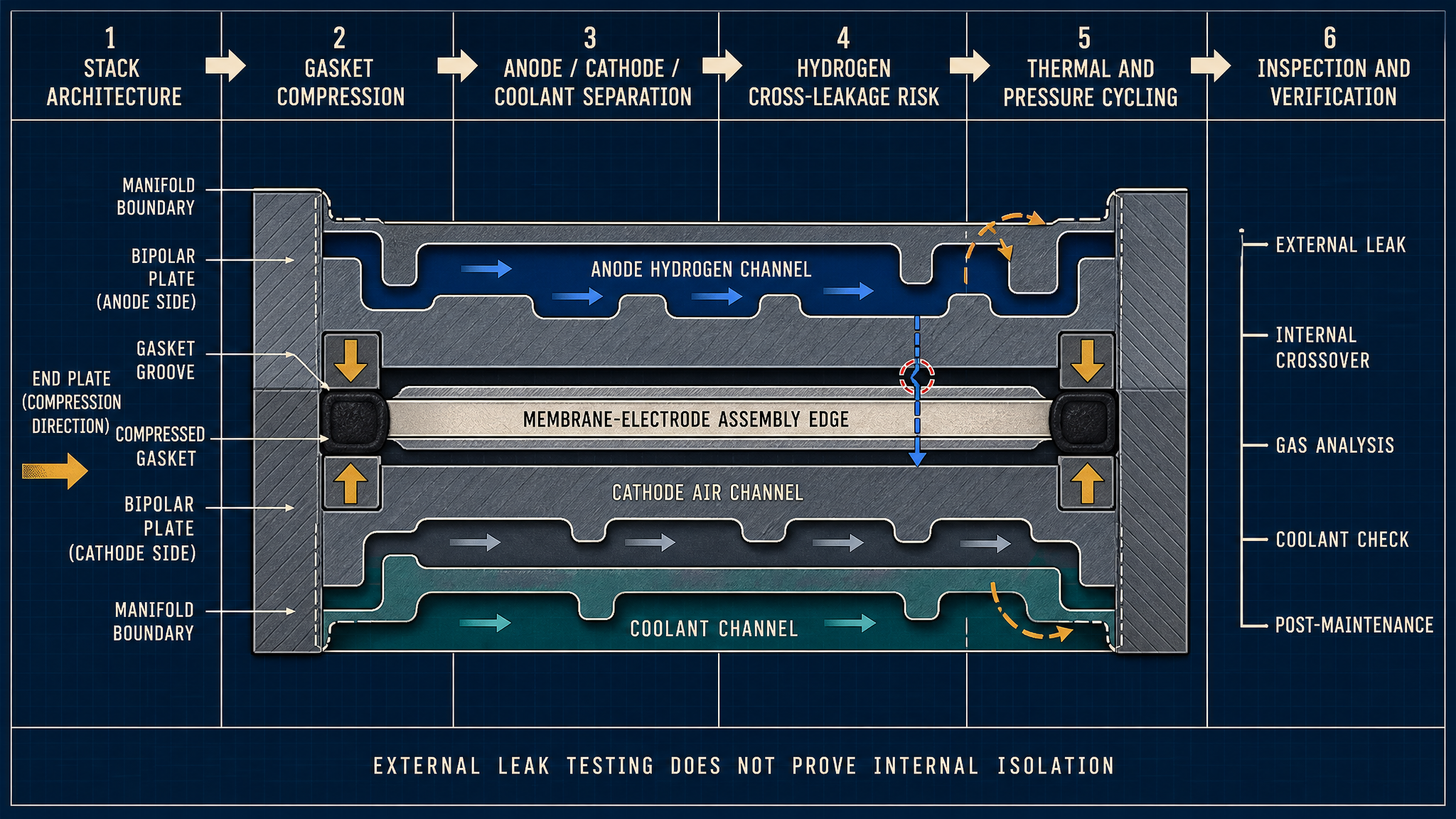
A stack is built from bipolar plates, membrane-electrode assemblies, gaskets, end plates and a compression structure. Bipolar plates form anode, cathode and coolant passages; the gasket groove defines the perimeter and manifold boundaries; end plates and tie rods distribute compression through the stack. Hydrogen inlet and outlet manifolds, air inlet and outlet manifolds and coolant inlet and outlet paths must remain isolated even when their boundaries are closely spaced.
Gas-channel perimeter gaskets separate the anode and cathode flow fields from the environment. Coolant-boundary gaskets separate the coolant channels from both gas paths. Manifold seals prevent one inlet or outlet from bypassing into another path. The bipolar-plate surface is part of the sealing interface: flatness, roughness, coating integrity and local damage determine whether nominal gasket compression becomes continuous contact. The membrane-electrode assembly is relevant to diagnosis because gas crossover through the electrochemical region is not automatically gasket leakage.
Table I: Fuel-Cell Stack Sealing Zones and Leakage Risks
|
Sealing zone |
Separated medium |
Main sealing function |
Typical failure |
Verification focus |
| Gas perimeter gasket | Anode, cathode, exterior | Isolate flow fields | Compression loss, extrusion | Differential leak test |
| Coolant boundary gasket | Coolant and gas paths | Prevent fluid crossover | Gas-to-coolant leak, ingress | Crossover test and coolant analysis |
| Manifold seal | Inlet and outlet paths | Prevent internal bypass | Manifold crossover | Port isolation test |
| Plate-to-gasket interface | Fluid and solid boundary | Maintain contact | Roughness, gap, surface damage | Plate and imprint inspection |
| End-plate compression boundary | Stack and exterior | Distribute load | Uneven compression, misalignment | Compression and alignment check |
The sealing zone, not the component name, determines the failure mechanism. A gasket can appear intact while a local plate gap causes leakage, and a plate crack can create a path that external inspection cannot reveal.
Gasket Compression and Stack Assembly
Gasket compression creates contact pressure, but the useful margin depends on groove geometry, material recovery, plate flatness and load distribution. Insufficient compression may leave a continuous or intermittent path. Excessive compression can accelerate compression-set loss, extrusion, tearing or local material damage. A nominal compression ratio therefore cannot be interpreted without the actual stack design and assembly condition.
Fastener sequence, end-plate stiffness and stack alignment influence compression uniformity. Local gaps may form near manifolds, corners or plate transitions even when the average stack load appears acceptable. Surface roughness can create micro-paths, while a damaged coating can change friction and contact. A displaced gasket may be compressed in one region and unsupported in another. Fixed bolt torque, compression or leakage values will not be treated as universal standards; they must follow the stack architecture, gasket material, pressure, temperature and manufacturer requirements.
Hydrogen Cross-Leakage and Coolant Isolation
The principal internal risks are anode-to-cathode leakage, anode-to-coolant leakage and cathode-to-coolant leakage. Anode hydrogen may cross through a failed gasket, manifold interface, bipolar-plate crack or local gap. Gas-to-coolant leakage can introduce hydrogen or air into the coolant loop without producing an external wet mark. Coolant ingress reverses the direction of concern: liquid enters a gas channel, potentially contaminating the flow path and changing local operation.
Hydrogen entering the cathode side can change gas composition and operating stability. Gas entering coolant can affect safety assessment, flow behavior and coolant condition. Coolant crossover can change composition, conductivity or contamination indicators. External hydrogen leakage is a boundary-to-environment event; internal cross-leakage is a boundary-to-boundary event. They require different isolation tests and should not be combined into one leakage category.
A gas concentration change must be interpreted with pressure, flow, sampling location, humidity and sensor response. Hydrogen permeation and membrane-electrode crossover may produce a gradual signal without an open gasket path. Conversely, a pressure-dependent step change may support a discrete path. Plate crack, manifold leakage, gasket damage and sensor or test-system error remain separate hypotheses until evidence identifies the path.
Table II: Compression, Thermal and Pressure Influence Matrix
|
Stress factor |
Primary effect |
Secondary effect |
Potential failure mode |
Required measurement |
Main limitation |
| Gasket compression | Contact-pressure change | Material set or extrusion | Insufficient or excessive compression | Compression map, imprint, dimensions | Design-specific |
| Plate flatness | Local gap or overload | Uneven load transfer | Cross-leakage, plate deformation | Flatness and stack alignment | Static geometry only |
| Thermal cycling | Modulus and dimension change | Stress relaxation | Thermal-cycle leakage | Temperature history and leak trend | Does not isolate chemistry |
| Humidity and wet-dry cycling | Material and interface change | Swelling or hardening | Gasket leakage, crossover | Humidity history and teardown | Depends on material and stack condition |
| Pressure cycling | Repeated interface loading | Crack or extrusion growth | Pressure-cycle leakage | Differential pressure and decay | May miss membrane crossover |
| Start-stop cycling | Repeated compression and expansion | Condensation or contamination | Intermittent leakage | Cycle history and gas data | Sequence-specific |
The matrix supports test planning, but it does not replace a design-specific definition of media, pressure, temperature, compression state and measurement method.
Thermal, Humidity and Pressure-Cycle Effects
Temperature gradients create differential expansion between bipolar plates, gaskets, coatings and surrounding hardware. Humidity and wet-dry exposure can alter dimensions, modulus, surface wetting and chemical interaction. Start-stop cycling repeatedly changes pressure and compression state, while pressure cycling changes local contact loading. Where freeze-thaw exposure is relevant, expansion and contraction can impose additional stress on grooves, manifolds and damaged interfaces.
Gasket stress relaxation and compression-set development reduce recovery after operation. Plate deformation can concentrate load at one edge and reduce it at another. A stack that passes one state may develop intermittent cross-leakage after thermal, humidity or pressure changes. The record should connect cycle history, differential pressure, gas composition, coolant condition and post-test morphology.
Materials and Interface Compatibility
Material selection should follow the complete interface. EPDM, FKM, FVMQ and HNBR may be considered under different hydrogen, air-side and coolant conditions, but compatibility depends on formulation, temperature, humidity, pressure and compression history. PTFE-based elements and engineered polymer gaskets can offer useful chemical or friction behavior in suitable geometries, but support, cold flow, sealing recovery and manufacturing tolerance require confirmation.
Coated bipolar plates, graphite plates and composite plates present different surface and structural risks. Coating damage may create a local sealing discontinuity or change contact friction. Graphite or composite plates may respond differently to load, surface damage and thermal gradients. Metal or polymer manifold interfaces add another tolerance and stiffness combination. Particle generation, extractables, swelling, hardening and permeation can affect the interface without immediately producing external leakage.
No gasket, bipolar-plate material or coating is a universal solution. Material screening must be followed by assembled-stack testing because plate flatness, groove geometry, compression uniformity, pressure differential, humidity and cycling can dominate the observed leakage behavior.
Inspection, Testing and Maintenance
External pressure-hold testing checks the selected exterior boundary, but it does not replace internal verification. Hydrogen detection can identify an external release or sampling signal, while helium testing can screen small paths under its own conditions. Neither result alone represents long-term hydrogen service. Differential-pressure and gas-to-coolant crossover tests address internal isolation.
Gas monitoring must retain pressure, flow, humidity, sampling location and calibration. Coolant analysis can identify contamination or gas interaction, but cannot prove every gas channel is isolated. Pressure-decay testing identifies loss under a defined condition. Thermal and start-stop cycling expose history-dependent changes. Compression, gasket, plate-surface and manifold inspections help localize a path.
Post-test teardown should examine gasket indentation, compression set, extrusion, tearing, swelling, hardening, displacement, bipolar-plate deformation, cracks, coating damage and surface contamination. After stack disassembly or gasket replacement, requalification should confirm material identity, groove cleanliness, gasket orientation, stack alignment, compression condition and internal isolation before return to service.
Table III: Fuel-Cell Stack Cross-Leakage Verification Guide
|
Test or inspection |
Test purpose |
Key variable |
Detectable issue |
Suitable stage |
Main limitation |
| External pressure-hold | Check exterior boundary | Pressure, duration, temperature | External leakage | Production and validation | Does not prove internal isolation |
| Hydrogen leak detection | Locate or trend hydrogen release | Sampling point, flow, calibration | External hydrogen leakage | Commissioning and service | Sensor and sampling effects |
| Helium leak test | Screen small paths | Test pressure and fixture | Fine external path | Component and validation | Not actual hydrogen service |
| Differential-pressure test | Challenge internal boundaries | Port pressure difference | Anode-cathode crossover | Design validation | Requires controlled ports |
| Gas-to-coolant test | Check fluid-path separation | Gas signal, coolant state | Internal gas ingress | Stack validation | Interpretation is system-dependent |
| Thermal and start-stop cycling | Expose history-dependent leakage | Temperature and cycle history | Intermittent leakage, set loss | Reliability validation | Does not identify one cause alone |
| Teardown inspection | Identify physical origin | Imprint, dimensions, surfaces | Crack, extrusion, damage | Failure analysis and service | Destructive and local |
Each result should retain stack identity, plate and gasket records, assembly sequence, compression condition, anode and cathode pressure, coolant pressure, temperature, humidity, cycle history, gas data, coolant analysis and corrective action.
Data Interpretation and Maintenance Planning
A useful record connects stack architecture with bipolar-plate material, gasket material and geometry, groove condition, compression, assembly sequence, anode pressure, cathode pressure, coolant pressure, temperature, humidity, cycle history, hydrogen concentration, pressure-decay result, coolant analysis, leakage trend, maintenance history and teardown morphology. This prevents a gas signal from being assigned to gasket ageing before plate, manifold, membrane-electrode and test-system causes are considered.
Maintenance may be calendar-based, operating-cycle-based, leakage-trend-based, gas-concentration-based, coolant-condition-based, post-shutdown or risk-based. Post-repair requalification should verify alignment, cleanliness, compression, gasket orientation and relevant internal isolation tests. Laboratory cycle counts and single-test results should not be converted directly into a universal fuel-cell system lifetime.
FMEA Risk Analysis
Table IV: Fuel-Cell Stack Sealing FMEA and RPN Analysis
|
Failure mode |
Cause |
Local/System effect |
Detection method |
RPN |
Corrective action |
| Anode-to-cathode cross-leakage | Gasket gap, manifold path or plate crack | Local gas mixing; altered cathode composition | Differential pressure and gas analysis | 225 | Improve interface control and isolate the path |
| Gas-to-coolant leakage | Coolant boundary damage or plate defect | Gas in coolant; safety and flow concern | Crossover test and coolant analysis | 240 | Add dedicated boundary validation |
| External hydrogen leakage | Perimeter seal, manifold or fitting defect | Hydrogen release outside stack | Hydrogen detection and pressure decay | 216 | Improve seal inspection and release criteria |
| Coolant ingress | Coolant boundary path or crack | Gas-channel contamination; local operation change | Coolant trace and teardown | 198 | Control plate integrity and boundary compression |
| Insufficient or uneven compression | Alignment, load distribution or groove error | Local gap; intermittent leakage | Compression map and imprint | 210 | Improve stack tolerance and assembly sequence |
| Gasket compression-set loss | Thermal, humidity and time exposure | Reduced recovery; recurring leakage | Dimension, imprint and cycling | 180 | Review material and compression margin |
| Gasket extrusion or damage | Excessive load, gap or rough surface | Local bypass; debris or tearing | Visual and surface inspection | 192 | Control gap, support and surface condition |
| Bipolar-plate deformation or crack | Load, thermal stress or handling damage | New internal or external leakage path | Flatness, imaging and teardown | 234 | Improve plate support and handling controls |
| Incorrect assembly or incomplete verification | Wrong gasket, misalignment or release after external test only | Hidden cross-leakage remains in service | Assembly audit and requalification | 252 | Require traceability and internal isolation tests |
The RPN values are illustrative engineering risk rankings, not field statistics or experimental results. They prioritize review; they do not replace design evidence or failure analysis.
Conclusion
Fuel-cell stack sealing depends on the combined behavior of bipolar-plate interfaces, gasket compression, stack alignment, anode-cathode-coolant separation, hydrogen containment and the compression structure. External hydrogen leakage, internal cross-leakage, gas-to-coolant leakage, coolant ingress, hydrogen permeation, membrane-electrode crossover, plate cracks and sensor error are different diagnostic categories.
Reliable verification must combine external and internal leakage tests, differential pressure, gas concentration, coolant condition, thermal and pressure-cycle history, compression inspection and post-test teardown. No single gasket, bipolar-plate material or compression arrangement eliminates every cross-leakage path. Maintenance reliability is established only after alignment, cleanliness, gasket condition, compression and internal isolation are requalified.
Engineering FAQ
Q:How does a fuel-cell stack gasket separate hydrogen, air and coolant?
A:The gasket follows dedicated grooves around gas fields, coolant channels and manifolds. Its compressed contact against the bipolar-plate surfaces forms separate boundaries, while end plates and the compression structure maintain load. Flatness, surface condition and compression uniformity determine whether those boundaries remain continuous.
Q:What is the difference between external hydrogen leakage and internal cross-leakage?
A:External hydrogen leakage releases hydrogen from the stack to the environment. Internal cross-leakage transfers gas between anode, cathode or coolant boundaries without necessarily producing an external signal. The two conditions require different port-isolation and detection methods.
Q:Why can a stack pass an external leak test but still have gas-to-coolant leakage?
A:An external test challenges the selected outside boundary. A local internal path between a gas channel and the coolant circuit may remain isolated from the exterior and therefore escape that test. Dedicated gas-to-coolant crossover testing and coolant analysis are required.
Q:How do temperature and pressure cycling affect bipolar-plate gasket sealing?
A:They change gasket modulus, dimensions, recovery and contact pressure while also deforming plates and interfaces. Repeated operation can create local gaps, compression-set loss, extrusion or intermittent leakage that is absent at one static condition.
Q:Which tests are needed after replacing fuel-cell stack gaskets?
A:Confirm gasket material, geometry, orientation, groove cleanliness, plate condition, alignment and compression. Then repeat the applicable external, internal differential-pressure, gas-to-coolant, pressure-decay and functional checks before release.
Q:How can hydrogen cross-leakage be distinguished from membrane-electrode gas crossover?
A:Compare pressure dependence, sampling location, flow behavior, coolant condition and stack-interface evidence. Membrane-electrode crossover may produce a gradual transport signal without a discrete gasket or plate path, whereas a pressure-dependent boundary change may indicate an interface or structural leak. Sensor calibration and test-fixture integrity must also be checked.
Post time: Aug-31-2026