
Executive Summary
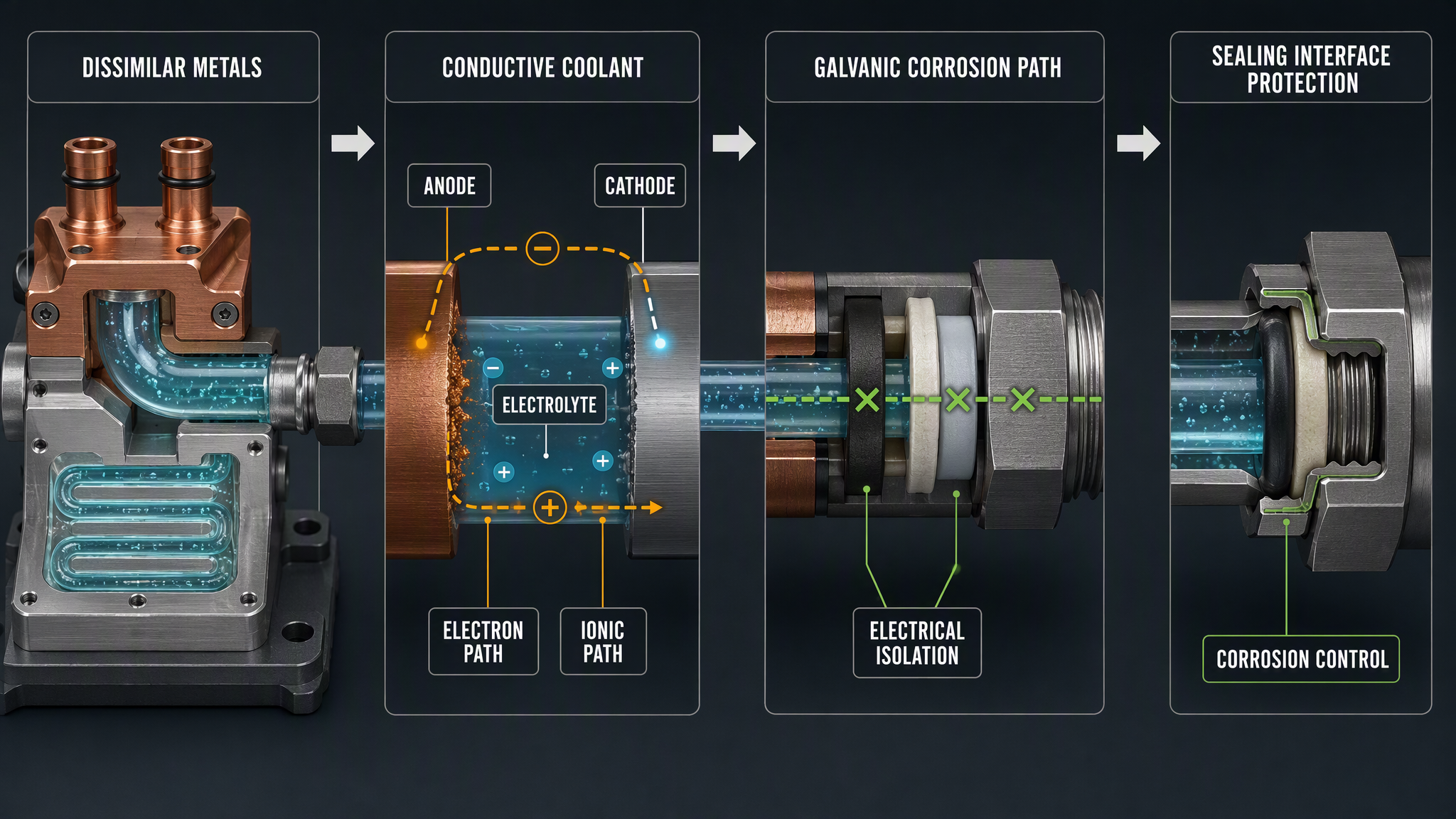
Galvanic corrosion in a liquid cooling system is an electrochemical architecture problem. It requires more than the presence of two different metals: an anodic and cathodic area, an electrolyte, an ionic path and an electrically continuous route for electrons must coexist. A conductive coolant can complete part of that circuit, while fittings, fasteners, mounting frames, heat exchanger plates, cold plates, pump bodies, valve bodies and grounding structures can complete another part.
The consequences extend beyond visible metal loss. Corrosion products can contaminate coolant, load filters, enter small passages, abrade seals and change the condition of heat-transfer surfaces. A damaged coating or a failed insulating gasket can expose a local crevice and allow ionic transport at a sealing interface. The resulting risk depends on the metal combination, exposed area ratio, coolant chemistry, oxygen, temperature, flow, electrical continuity and time.
Reliable isolation therefore follows a connected sequence: identify dissimilar metals, control conductive bridges, interrupt unwanted electrical paths, protect sealing interfaces and verify the coolant and structure during service. Low conductivity may reduce one part of the electrochemical response, but it does not replace material compatibility review, coating inspection, isolation checks or maintenance discipline.
Galvanic Corrosion Mechanism in Liquid Cooling
A galvanic cell forms when dissimilar electrochemical surfaces are electrically connected and exposed to an electrolyte. The less noble surface acts as the anode and can dissolve; the more noble surface is the cathode and supports a cathodic reaction. The coolant may provide the ionic path when it contains enough mobile ions. A metal-to-metal joint, conductive fastener, frame, grounding conductor or other electrically continuous structure may provide the electron path.
The same system may contain several local cells rather than one simple pair. A copper cold plate connected to an aluminum manifold, a stainless fitting attached to a copper tube, a brass component beside a stainless body, or a nickel-plated surface with a coating defect can create different local conditions. Area ratio, crevice geometry, temperature gradients, oxygen access and deposits can make one location more active than another. These are engineering examples, not universal failure predictions.
Not every corrosion mark is galvanic corrosion. Uniform corrosion can occur across a compatible surface, pitting can be driven by local chemistry, crevice corrosion can develop in shielded gaps, erosion-corrosion can be linked to flow and deposit removal, and deposit-related attack can occur beneath accumulated solids. Correct classification is necessary before choosing an isolation measure.
Dissimilar Metals and System Architecture
The first control point is the material architecture. Build a metal map for every wetted component and every conductive connection, including hidden fasteners, inserts, support brackets, grounding straps, heat exchanger plates, cold-plate covers, pump and valve bodies, and plated surfaces. Mark direct contact, coolant contact, coating boundaries and paths that can bypass an intended insulating barrier.
Copper and aluminum combinations deserve explicit review because their electrochemical behavior and surface condition may differ substantially. Copper with stainless steel, aluminum with stainless steel, brass with stainless steel and nickel-plated parts joined to exposed base metal also require system-specific assessment. The risk is not determined by a material name alone. Surface area, alloy condition, plating integrity, coolant chemistry, electrical continuity and temperature must be considered together.
Table I: Dissimilar Metals and Galvanic Corrosion Risk
|
Metal combination |
Potential risk |
Coolant condition |
Likely location |
System consequence |
Isolation approach |
| Copper and aluminum | Potential cell when electrically connected | Conductive or ion-contaminated coolant | Cold plate, manifold or fitting | Localized metal loss and ion release | Material matching, dielectric break and coating review |
| Copper and stainless steel | Risk depends on area, surface state and continuity | Oxygenated or contaminated coolant | Heat exchanger, tube joint or fastener | Deposit or particle generation | Interrupt contact path and inspect joint design |
| Aluminum and stainless steel | Crevice and coating defects can localize attack | Conductive coolant with pH drift | Frame, manifold or plated interface | Leak path or structural weakening | Isolation sleeve, gasket and coating integrity control |
| Brass and stainless steel | Different potentials and trapped electrolyte may combine | Aged or mixed coolant chemistry | Valve, adapter or service connection | Ion contamination and sticking deposits | Use controlled materials and sealed crevice geometry |
| Nickel-plated base metal | Plating defect exposes a different substrate | Coolant reaches damaged plating | Fitting, plate or fastener edge | Small active area with local attack | Inspect plating, limit damage and isolate substrate |
| Mixed metal fittings | Coolant bridges separate metals even without direct touch | High ionic load or cleaning residue | Manifold and service assembly | Distributed corrosion risk and contamination | Reduce combinations and validate complete assembly |
The table is an architecture-screening tool. It does not rank every alloy or prove compatibility. A final decision requires the actual alloy, surface condition, coolant, temperature history, electrical path and verification method.
Conductive Coolant and Electrochemical Risk
Coolant conductivity indicates the ability of the fluid to carry ionic current, but it is not a complete corrosion diagnosis. Ionic contamination, aggressive ions, dissolved oxygen, pH drift, temperature, coolant aging, cleaning-agent residue, mixed chemistry and accumulated metal ions can change the electrochemical environment without producing the same conductivity value. A single reading can therefore hide a changing risk state.
Repeated topping-up can introduce a different water or inhibitor balance, while cleaning residue can alter pH or ionic content. Higher temperature can accelerate reaction rates and change gas or ion transport. Flow can remove products from one surface and deposit them in another. Low flow may promote local concentration and deposits, whereas high flow can expose fresh surface after erosion or damage. These interactions require trend records rather than one universal threshold.
Table II: Conductive Coolant Factors and Corrosion Control
|
Factor |
Corrosion mechanism |
Monitoring method |
Warning signal |
Main limitation |
Recommended control |
| Conductivity | Ionic path becomes more effective | Trend meter and sample check | Rising or unstable trend | Does not identify ion species or metal pair | Investigate source and correlate with chemistry |
| Ionic contamination | Supports localized cell and deposits | Ion or laboratory analysis | Specific ion or metal-ion increase | Sampling and analysis may be delayed | Control fill water, residue and maintenance inputs |
| Dissolved oxygen | Supports cathodic reaction at exposed surface | Coolant sampling or validated sensor | Change after service or exposure | Result depends on sampling and location | Limit air exposure and verify system condition |
| pH drift | Changes surface film and reaction balance | pH trend with calibrated method | Persistent shift from baseline | No universal value fits every material | Trace source and assess materials together |
| Temperature | Changes reaction rate and fluid chemistry | Supply, return and local trend | Corrosion signal follows thermal change | Sensor may miss local hot spots | Review temperature history and surface condition |
| Metal ions and particles | Products transport and deposit elsewhere | Ion and particle analysis | Filter loading or particle rise | May not identify original source | Inspect deposits, filters and active interfaces |
| Coolant aging or mixing | Chemistry and protection balance changes | Batch record and sample comparison | Post-fill conductivity or pH shift | Cause can be distributed | Control additions and document each change |
Coolant monitoring should be interpreted with the metal map and electrical architecture. A low-conductivity reading can coexist with a direct metal contact, a damaged coating, a trapped contaminant or a local wet path that still requires isolation.
Sealing Interface and Isolation Protection
Sealing interfaces can interrupt unwanted liquid paths and reduce direct metal contact, but their electrical isolation function must be designed rather than assumed. An insulating gasket or O-ring may separate two surfaces while also controlling the crevice where coolant could collect. Non-metallic washers and isolation sleeves can interrupt fastener contact. Coated contact surfaces can reduce exposure when coating integrity is maintained. Electrically isolating fittings and dielectric barriers can separate components that would otherwise share a conductive path.
The interface remains a service item. Swelling, compression set, wear, extrusion, misalignment, surface damage or loss of clamping force can open a path for coolant and ions. A coating scratch can expose a small active area beside a larger cathodic area. Deposits can bridge a nominal gap. A seal therefore supports isolation only while its geometry, chemistry, compression and surface condition remain within the design boundary.
Protection should include controlled fastener contact, sealed crevice design, coating inspection and a defined verification method. The method may combine electrical continuity or isolation resistance checks with coolant sampling, visual inspection, pressure testing and post-maintenance review. No single seal, coating or coolant can be treated as a complete galvanic-corrosion solution.
Table III: Sealing Interface and Electrical Isolation Protection
|
Protection element |
Isolation function |
Main failure mode |
Compatibility concern |
Verification method |
Maintenance action |
| Insulating gasket | Separates wetted metal faces and limits ionic bridge | Compression loss, cut or creep | Pressure, temperature and coolant exposure | Visual, compression and isolation check | Replace and inspect mating surfaces |
| O-ring | Closes crevice and blocks fluid path | Swelling, wear, extrusion or misalignment | Fluid chemistry and long-term compression | Dimensional, visual and leak check | Use approved material and correct installation |
| Non-metallic washer | Interrupts fastener conduction | Crack, omission or bypass contact | Load, temperature and washer material | Assembly audit and resistance check | Replace damaged parts and control torque |
| Isolation sleeve or fitting | Separates fastener, tube or body path | Crush, puncture or conductive contamination | Pressure, temperature and fluid compatibility | Continuity and insulation check | Inspect bore, sleeve and contact surfaces |
| Coated contact surface | Blocks exposure of base metal | Scratch, pore, blister or edge damage | Coating adhesion and coolant aging | Coating inspection and coupon evidence | Repair only by qualified process or replace |
| Dielectric barrier | Interrupts intentional electrical path | Bridging, bypass or wrong assembly | System grounding and service practice | Isolation map and resistance check | Restore barrier and document configuration |
| Sealed crevice control | Limits stagnant ionic volume | Deposit, seal damage or trapped residue | Cleanability and compression stability | Visual inspection and sampling | Clean, replace and re-verify interface |
The protection matrix links isolation hardware to its failure boundary. The key question is not whether an insulating component was installed, but whether the complete interface still blocks the intended conductive and ionic paths after assembly, operation and maintenance.
Corrosion Products and System-Level Effects
Corrosion products can migrate from the original cell and become a second system problem. Dissolved metal ions may precipitate when chemistry or temperature changes. Particles can load filters, collect in low-flow regions, enter small passages or abrade seal surfaces. Deposits on heat-transfer surfaces can change the local interface, while deposits around a gasket, O-ring or coating edge can create a new electrolyte bridge.
A valve may stick because deposits change its contact or clearance. A pump may experience wear because particles circulate through a narrow clearance. A cold plate or heat exchanger may show local fouling. Conductivity may drift as ions are released or removed. These symptoms do not prove a galvanic source, but they justify tracing particles, metal ions, deposits and the material map together.
Inspection, Testing and Maintenance
Inspection should establish a baseline before commissioning and repeat it after service events. Conductivity and pH trends describe coolant condition; sampling and metal-ion analysis can identify contamination that a conductivity value cannot classify. Particle analysis and filter inspection show transported products. Visual inspection can reveal coating damage, discoloration, deposits and crevice wetting, but hidden surfaces require disassembly or a validated indirect method.
Electrical continuity checks identify an unintended conductive path; isolation resistance checks assess whether a designed barrier still interrupts that path. Neither test proves coolant compatibility. Pressure and leakage tests confirm boundary integrity, while coupon testing and material compatibility testing can provide evidence for a specific metal, coating, seal and coolant combination. Results must be recorded with component identity, coolant batch or condition, temperature history, sampling location and maintenance action.
Maintenance is a corrosion-control step. Before replacing a fitting, gasket, washer or coated part, preserve the isolation map and identify every conductive bridge. Prevent tools, fasteners, cleaning residue and replacement components from re-establishing metal contact. After assembly, verify the barrier, inspect the interface, sample the coolant when required and document the post-maintenance condition.
FMEA Risk Analysis
The following rankings are illustrative engineering assessments, not field statistics. They show how a galvanic-isolation failure can propagate from a local material or assembly condition to coolant contamination, seal damage or reduced system availability. Actual occurrence, severity and detection scores must be established from the specific design and service history.
Table IV: Galvanic Corrosion FMEA and Illustrative Risk Ranking
|
Failure mode |
Cause |
Local effect |
System effect |
Detection method |
Risk ranking |
Corrective action |
| Direct dissimilar-metal contact | Isolation omitted or bypassed | Local electrochemical cell | Metal loss and ion release | Material map and continuity check | High | Restore barrier and review assembly |
| Conductive coolant bridge | Ion-rich coolant enters joint or crevice | Ionic path across metals | Corrosion products and contamination | Conductivity, ions and visual inspection | High | Control coolant and seal crevice |
| Damaged insulating coating | Scratch, pore or edge defect | Base metal exposed | Localized attack and particles | Coating inspection and sample analysis | High | Repair by qualified method or replace |
| Seal compression loss | Creep, wear or wrong compression | Coolant path opens at interface | Ion migration and local leakage risk | Dimensional, pressure and isolation check | High | Correct geometry and replace seal |
| Wrong gasket or O-ring material | Incompatible selection or substitution | Swelling or loss of isolation | Re-established conductive path | Material record and post-service inspection | High | Control specification and approval |
| Contaminated coolant | Residue, poor fill water or mixing | Electrolyte becomes more active | Accelerated cell response | Conductivity, pH and ion analysis | High | Remove source and restore coolant condition |
| pH drift | Aging, residue or mixed chemistry | Surface film changes | Localized corrosion or deposits | Calibrated pH trend and sample | Medium | Trace cause and validate chemistry |
| Excessive dissolved oxygen | Air exposure or service ingress | Cathodic reaction supported | Higher corrosion tendency in exposed cell | Coolant analysis and maintenance review | Medium | Limit exposure and inspect ingress path |
| Electrical grounding bypass | Frame, fastener or cable bridges barrier | Unintended electron path | Cell persists despite coolant control | Isolation map and resistance check | High | Correct grounding architecture |
| Corrosion-product accumulation | Products migrate and deposit | Crevice or passage becomes active | Filter load, fouling and seal abrasion | Particle, filter and deposit inspection | Medium | Clean source, filter and re-verify |
| Maintenance-induced metal contact | Replacement part or tool bypasses isolation | New local cell at service joint | Recurring contamination after service | Assembly audit and continuity check | High | Use controlled kit and documented sequence |
| Local crevice corrosion | Stagnant electrolyte under seal or coating edge | Localized metal loss | Delayed leak or structural concern | Disassembly and surface inspection | Medium | Redesign crevice and improve cleanability |
| Metal-ion contamination of sensitive parts | Corrosion source upstream | Ion and particle transport | Valve, pump or cold-plate reliability loss | Ion analysis and component inspection | High | Isolate source and clean affected circuit |
FMEA is most useful when the failure mode has a physical cause, a local effect, a system symptom and a verification method. The ranking directs design review; it is not a substitute for corrosion testing or service evidence.
Conclusion
Galvanic corrosion isolation in a liquid cooling system starts with the metal map. Dissimilar metals become a system risk when a conductive coolant, an ionic path and electrical continuity allow a local electrochemical cell to persist. The risk is shaped by surface condition, area ratio, oxygen, pH, temperature, flow, deposits and time, not by a material label alone.
Sealing interfaces, insulating gaskets, sleeves, washers, coatings and dielectric barriers can interrupt selected paths, but they remain subject to pressure, temperature, coolant compatibility, compression loss, wear, damage and maintenance error. Coolant conductivity, pH, metal-ion and particle trends provide operating evidence, while continuity, isolation, coating, coupon and compatibility tests verify specific design assumptions. Reliable control therefore requires coordinated material selection, structural isolation, coolant monitoring, electrical-path review and disciplined maintenance.
Engineering FAQ
Q:What creates a galvanic corrosion cell in a liquid cooling system?
A:A cell requires dissimilar electrochemical surfaces, an electrolyte, an ionic path and an electrical connection. The coolant may carry ions, while metal joints, fasteners, frames, grounding paths or conductive deposits can complete the electron route.
Q:Why do dissimilar metals become more risky with conductive coolant?
A:A conductive coolant can carry ionic current between surfaces that are electrically connected through the hardware. The resulting risk depends on the metal pair, exposed area, surface condition, oxygen, pH, temperature, deposits and exposure time; conductivity alone does not determine the outcome.
Q:How can sealing interfaces help isolate galvanic corrosion?
A:A correctly designed gasket, O-ring, washer, sleeve, coating or dielectric barrier can limit direct contact and prevent coolant from entering a conductive crevice. Its protection remains valid only while compression, geometry, chemical compatibility and surface integrity are maintained.
Q:Can low coolant conductivity eliminate galvanic corrosion risk?
A:No. Lower conductivity may reduce ionic transport, but it cannot correct direct metal contact, a damaged coating, trapped contamination, an unintended grounding path or a failed seal. Coolant readings must be interpreted with the material and isolation architecture.
Q:Which tests can detect early galvanic corrosion?
A:Trend conductivity, pH, metal ions, particles, filter loading and temperature together with visual, coating, continuity and isolation checks. Coupon or compatibility testing can support a defined material and coolant combination, but no single test validates the complete system.
Q:How can maintenance activities reintroduce galvanic corrosion paths?
A:A replacement fastener, fitting, gasket, washer, coating repair or cleaning residue can bypass an intended barrier or change the coolant chemistry. Preserve the isolation map, control replacement parts, verify continuity and isolation, inspect the interface and record the post-maintenance coolant condition.
Post time: Aug-27-2026