
Executive Summary
An automatic deaeration-valve seal does not face one static coolant pressure. It moves through gas exposure, liquid wetting, pressure variation and mechanical reclosure while the valve body, float, poppet, diaphragm or spring-loaded element changes the local sealing load. Air release can therefore alter contact pressure, friction and local compression before the seal is asked to close again.
After liquid rewetting, the closing element may not immediately recover uniform contact at the valve seat. Gas leakage, coolant seepage, gas retention and coolant contamination are different consequences, and a static liquid pressure-hold test cannot prove reliable closure after gas-liquid alternation. Automatic deaeration-valve sealing should be evaluated as a gas-liquid alternating interface rather than as a static seal exposed to one continuous coolant phase.
Automatic Deaeration-Valve Architecture and Sealing Boundaries
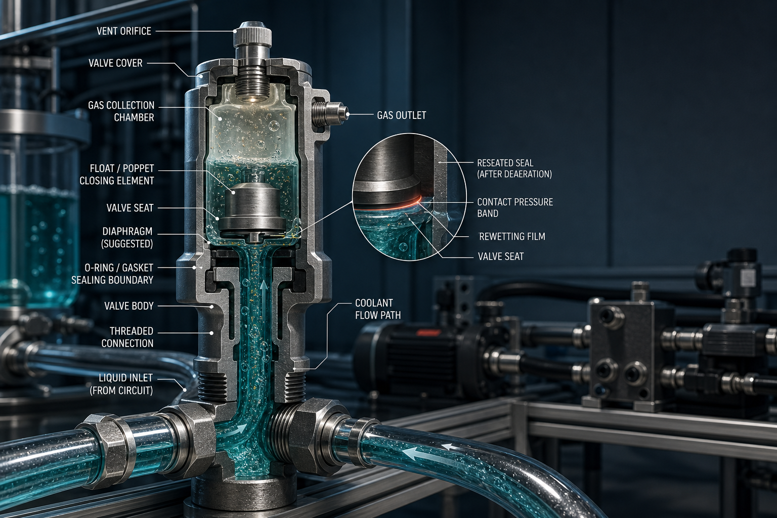
In a CDU or secondary liquid-cooling loop, an automatic deaeration valve usually contains a valve body, valve cover, gas collection chamber, liquid inlet, gas outlet, valve seat, vent orifice and threaded or flanged connection. Depending on architecture, closure force may come from float buoyancy, poppet seating, diaphragm deflection, spring preload or a combined pressure-assisted mechanism. The internal gas pocket region and the wetted flow path do not share the same exposure history.
The vent outlet is a controlled gas release path, not a conventional liquid relief port. As the gas-liquid interface moves, buoyancy, gravity, spring force and differential pressure change together. Inlet flow, installation orientation, high-point location and chamber geometry determine whether gas accumulates at the intended region or remains distributed as bubbles, foam or liquid carryover near the seat.
Risk assessment must separate the coolant-side pressure boundary, gas-chamber boundary, valve-seat sealing boundary, vent-outlet boundary, valve-cover sealing boundary, threaded or flanged connection boundary, and drain or service boundary. A valve-seat leak after reclosure, a valve-cover seep, a threaded-interface leak and a blocked vent path have different evidence patterns and should not be merged into one generic seal risk.
Table I: Automatic Deaeration-Valve Pressure Boundaries and Seal Functions
| Boundary | Exposure | Seal function | Risk | Verification | Limitation |
| Valve-seat seal | Gas and liquid | Block vent after release | Incomplete closure | Closing response | Load varies |
| Float or poppet interface | Mixed phase | Transfer closing force | Sticking or skew | Movement check | Sensitive to debris |
| Diaphragm edge seal | Gas and liquid | Separate chamber volumes | Crease or fatigue | Flex test | Bending history matters |
| Valve-cover seal | Liquid boundary | Hold body pressure | Cover seepage | Liquid hold | Not seat proof |
| Threaded connection | External joint | Seal installation joint | Air ingress or seep | Joint leak test | Assembly dependent |
| Vent outlet | Gas path | Release collected gas | Liquid carryover | Venting response | Not relief valve |
| Drain or service port | Service boundary | Hold after maintenance | Particle entry | Post-service test | Reuse risk |
| Gas chamber | Gas pocket | Collect air | Gas retention | Observation | Orientation dependent |
Formation of Gas-Liquid Alternation in Cooling Circuits
Gas-liquid alternation begins during initial filling when incomplete air removal leaves residual gas in high points, branch loops or the deaeration chamber. Pump start-up, speed change and shut-down can move gas pockets into the valve, break bubbles into smaller volumes or merge them into larger pockets. Parallel-loop imbalance and local pressure reversal can change which side of the valve sees gas first.
Temperature changes affect dissolved gas release, coolant degassing and bubble volume. Pressure reduction can promote gas release or allow external air ingress if local pressure becomes low enough during cooling contraction or pump coast-down. Bubble breakup, coalescence, liquid carryover and foaming create short pressure and wetting transients around the valve seat, especially when the vent-port orientation or piping slope delays stable gas collection.
The risk cannot be described only as air in the system. Gas-volume variation, liquid-level variation, pressure amplitude, rise and drop rate, alternation frequency, gas residence time, flow direction, coolant temperature, gas carryover and venting duration all matter. Without those variables, fixed bubble size, fixed pressure peak, fixed vent count or universal deaeration efficiency would be unsupported.
Seal Compression, Wetting, Valve Motion and Alternating Failure
Initial squeeze and contact pressure define the seal reserve, but gas exposure changes lubrication and friction at the interface. A dry or partially wetted valve seat can increase adhesion and stick-slip. When coolant rewets the seat, the residual film may reduce friction, move particles, or create a temporary hydraulic separation that delays complete reseating.
Float movement, poppet seating, diaphragm deflection and spring preload convert pressure variation into changing seal load. A slight float or poppet misalignment can create circumferential contact discontinuity. A diaphragm may crease under repeated bending, while repeated closing impact can roll, twist, pinch or extrude an O-ring or profiled seat seal. Pressure-assisted sealing may help in one direction but become pressure-unassisted or unstable during reversal.
High compression can accelerate compression set and stress relaxation; low compression can leave a microchannel during gas-liquid transition. Particle indentation, machining burrs, crystalline residue and seat wear can prevent full contact after deaeration. Intermittent coolant wetting, gas leakage after reclosure, coolant seepage at the vent outlet, float sticking, poppet chatter, repeated pressure-decay drift and air re-entry after pump shut-down should be treated as separate evidence, not as one symptom.
Table II: Gas-Liquid Alternation and Seal-Risk Matrix
| Factor | Primary effect | Secondary effect | Failure mode | Control | Limitation |
| Initial filling | Residual gas | Unstable wetting | Delayed closure | Filling procedure | No fixed air volume |
| Pump start-up | Bubble migration | Seat impact | Poppet chatter | Ramp control | Loop dependent |
| Pump shut-down | Pressure drop | Air re-entry | Gas leakage | Decay test | Not liquid leak |
| Thermal degassing | Bubble growth | Pressure shift | Gas retention | Thermal cycling | Temperature specific |
| Liquid carryover | Mixed vent flow | Float damping | Coolant seepage | Vent geometry | Foam dependent |
| Diaphragm cycling | Repeated flexure | Crease growth | Incomplete closure | Response test | Material dependent |
| Particle entrapment | Local support | Seat scratch | Microleak | Cleanliness control | Hidden debris |
| Rewetting delay | Friction shift | Adhesion | Stick-slip | Alternation cycling | Static test misses it |
Coolant Chemistry, Temperature, Particles and Maintenance Interaction
Water-glycol coolant, dielectric coolant, inhibitors, additives, dissolved gas, oxidation products and cleaning agents can change rubber absorption, extraction, swelling, shrinkage, softening, hardening, surface tackiness and rebound. A material that survives immersion may still show unstable friction or recovery when repeatedly exposed to gas and then rewetted by residual coolant film.
Thermal cycling changes dimensions of the float, poppet, valve body and seal at different rates. Particles from metal debris, filter debris, wear debris or processing residue can embed in the seal, support the seat locally, scratch the contact band or form a persistent microleak path. Cleaning agents, lubricants and coolant residue may interact at the seat rather than acting independently.
Drain and refill events change chamber cleanliness and the gas-liquid interface. Maintenance can introduce particles, twist a seal, scratch a seat or disturb guide clearance. Seal wear particles, diaphragm fragments or valve-seat debris can then contaminate the cooling loop. External liquid traces must also be distinguished from condensation or handling residue before the root cause is assigned.
Seal Material, Valve Geometry and Deaeration-Path Design
EPDM, FKM, FVMQ, NBR, HNBR, silicone, FFKM, PTFE-encapsulated seals, miniature O-rings, flat gaskets, molded diaphragms, profiled seals, backup rings, bonded seals and liquid-applied sealants may all be considered, but none is universally best. Selection must compare coolant compatibility, gas exposure response, rewetting response, compression-set resistance, stress relaxation, friction stability, stick-slip tendency, extrusion resistance, particle tolerance, gas permeability, low-temperature flexibility, thermal-cycle response, installation repeatability, cleaning compatibility, long-term aging and main limitation.
O-rings, flat gaskets, diaphragm edge seals and valve-seat seals carry load differently. Seat angle, contact width, seal section, groove depth and guidance affect closing repeatability. High differential pressure or pressure-direction change may require support against extrusion. Float or poppet mass, guide clearance and surface roughness can determine whether the seal closes smoothly or arrives skewed.
Soft compounds may conform to small defects but become tacky, extrude or acquire compression set. Hard compounds may resist extrusion yet fail to accommodate seat error, thermal distortion or particles. Diaphragm materials must tolerate gas-liquid alternation, repeated flexure and chemical exposure. Coolant resistance alone is not proof of long-term response under alternating gas, liquid and repeated closure.
Inspection, Testing and Failure-Analysis Logic
A credible investigation begins by classifying evidence as observed, suspected, confirmed, inconclusive or not evaluated. Visual inspection, magnified valve-seat inspection, float or poppet movement inspection, diaphragm inspection, dimensional inspection, seat concentricity, roughness, seal cross-section, groove depth, hardness, compression set and stress relaxation establish whether the parts could create uniform contact before dynamic testing begins.
Coolant immersion, gas exposure, gas-liquid alternation cycling, thermal cycling, static liquid pressure holding, static gas pressure holding, pressure decay, air-ingress testing, liquid leakage testing and helium leak testing answer different questions. A static liquid hold cannot replace alternation cycling; gas leak testing does not prove coolant will not migrate; liquid leakage testing does not prove external air cannot enter under local negative pressure. Helium leakage can reveal small gas channels but not valve motion quality.
Venting tests should record gas state, liquid state, pressure, temperature, flow, response time and reseating condition. Merely logging open or closed does not prove sufficient contact pressure. Disassembly may create new scratches, particles or misalignment, so the failed seal, seat, body, float or poppet, diaphragm, coolant and test records should be retained and compared with an unused seal.
Table III: Automatic Deaeration-Valve Seal Verification Guide
| Test | Objective | Variable | Detectable issue | Stage | Limitation |
| Coolant immersion | Screen compatibility | Medium and time | Swelling or hardening | Material selection | Not motion proof |
| Gas exposure | Assess dry response | Gas dwell | Hardening or tack | Design validation | No rewetting |
| Liquid rewetting | Check recovery | Film and timing | Delayed closure | Mechanism study | Condition specific |
| Static liquid hold | Find liquid path | Pressure state | Coolant seepage | EOL or service | No gas alternation |
| Static gas hold | Find gas path | Gas pressure | Gas leakage | Bench check | Not coolant migration |
| Alternation cycling | Replicate phase change | Phase and pressure | Stick-slip or drift | Reliability test | Needs trace |
| Air-ingress test | Check inward path | Low pressure | External air entry | System validation | Not liquid leak |
| Helium leak | Find microchannel | Tracer gas | Small gas path | Failure analysis | No motion proof |
| Contamination analysis | Identify debris | Coolant sample | Wear or residue | Root cause | Source may vary |
| Post-service test | Verify maintenance | Assembly state | Reuse or handling risk | Field service | Only current state |
Maintenance, Process Control and Long-Term Reliability
Installation orientation, vent-port orientation and high-point location directly affect gas collection and valve motion. Filling, air-removal procedure, pump start-up sequence, pressure monitoring, temperature monitoring and valve response monitoring should confirm that the chamber does not retain a persistent gas pocket after coolant refill.
Maintenance creates its own failure modes: seal twisting, groove contamination, seat scratching, float guide interference, incorrect lubricant and particle entrapment. Reuse decisions should not rely on appearance alone. Float or poppet inspection, diaphragm replacement criteria, seal replacement criteria, seat cleaning, groove cleaning and particle removal must be tied to post-maintenance verification.
After service, gas discharge, closing recovery, liquid holding and air-ingress resistance should be checked separately. Seal batch, valve-body batch, coolant batch, maintenance record and test record should remain traceable. If seat geometry, float, poppet, diaphragm, spring, vent orifice or coolant changes, gas-liquid alternating response should be revalidated. Reliability comes from path design, motion stability, medium control and dynamic evidence, not merely higher compression.
FMEA Risk Analysis: Automatic Deaeration-Valve Sealing Under Gas-Liquid Alternation
Residual gas, bubble migration, pump motion and temperature change create alternating gas and liquid exposure inside the deaeration valve. That alternation changes wetting, friction, compression and contact pressure, while the float, poppet or diaphragm may stick, skew, impact the seat or fail to recover. The valve body, seat, seal, guide, spring, vent outlet, coolant and maintenance process must therefore be included in the same FMEA. The RPN values are illustrative engineering risk rankings, not field statistics or experimental results.
Table IV: FMEA Risk Analysis
| Failure mode | Cause | Local effect | System effect | Detection | RPN | Action |
| Residual air retention | Incomplete filling | Gas pocket remains | Poor deaeration | Gas observation | 168 | Improve fill and bleed |
| Incomplete vent closure | Rewetting delay | Seat gap | Gas leak or seep | Response test | 190 | Revise seat and timing |
| Float or poppet sticking | Debris or tack | Delayed motion | Air retention | Movement check | 176 | Clean guide and control debris |
| Poppet misalignment | Guide clearance | Uneven contact | Pressure-decay drift | Concentricity check | 162 | Improve guidance |
| Diaphragm crease | Repeated flexure | Local fold | Incomplete sealing | Diaphragm inspection | 154 | Revise profile |
| Spring preload loss | Relaxation | Low force | Reclosure failure | Force check | 140 | Control spring material |
| Seat contamination | Particles or residue | Local support point | Microleak | Magnified inspection | 184 | Clean and filter |
| Seal extrusion or rolling | Gap and impact | Damaged section | Coolant seepage | Teardown | 170 | Add support or geometry change |
| Compression-set growth | High squeeze or heat | Poor recovery | Leak after cycles | Set test | 158 | Adjust squeeze and material |
| Coolant swelling or shrinkage | Medium mismatch | Friction and size drift | Unstable response | Immersion test | 150 | Validate coolant compatibility |
| Vent-orifice blockage | Debris or foam | Gas cannot escape | Gas retention | Flow test | 145 | Improve path cleanliness |
| Air ingress after shutdown | Low pressure path | Inward leakage | Bubbles return | Air-ingress test | 188 | Separate inward-leak control |
| Threaded or cover leak | Assembly error | External seep | Coolant loss | Joint leak test | 132 | Control torque and seal reuse |
| Inadequate alternation validation | Static-only release | Risk hidden | False confidence | Test-plan audit | 196 | Add gas-liquid cycling |
Conclusion
Automatic deaeration-valve seals experience a combined load of gas exposure, liquid rewetting, pressure variation and valve movement. Bubble accumulation, pump transients, temperature change, liquid carryover, particles and maintenance work can all change the sealing interface. Seat geometry, guide design, float or poppet motion, diaphragm response, seal material and valve-body stiffness must be evaluated together.
Gas retention, liquid holding, venting response and air-ingress resistance are not interchangeable tests. A valve that opens and closes is not automatically a reliable long-term seal. Without gas-liquid alternation cycling and post-cycle evidence, an automatic deaeration-valve sealing structure should not be claimed reliable for long-term liquid-cooling service.
Engineering FAQ
Q:Why can trapped air affect the sealing performance of an automatic deaeration valve?
A:Trapped air changes buoyancy, local pressure and wetting at the valve seat. The seal may shift from liquid-lubricated contact to dry or partially wetted contact, then back again during rewetting. Temperature, particles, coolant compatibility and maintenance residue can amplify this change. Gas leakage and coolant leakage are not equivalent, and one static test cannot prove alternating reliability.
Q:How is gas-liquid alternating response different from a static pressure test?
A:A static test holds one pressure state and one exposure condition. Gas-liquid alternation adds interface movement, bubble coalescence, foam, liquid carryover, valve motion and reclosure. It can reveal sticking, delayed reseating, friction drift or air ingress that a static liquid hold misses. Gas and liquid leakage paths must be evaluated separately.
Q:Can a deaeration valve leak after it appears to close normally?
A:Yes. A float, poppet or diaphragm may reach the closed position while contact pressure remains uneven. Particles, swelling, compression set, seat residue or a rewetting delay can leave a microchannel. Apparent closure is a kinematic observation, not proof of sealing force. Pressure decay, leakage and post-cycle inspection are still required.
Q:How do pump start-up and shut-down affect automatic deaeration-valve seals?
A:Start-up can drive gas pockets and bubbles into the chamber; shut-down can reduce pressure, reverse local flow or permit air re-entry. These events change gas volume, liquid level, pressure rate and closing load. Temperature contraction and particles may add further risk. Static tests cannot represent this start-stop history.
Q:Why can liquid carryover or foam interfere with valve closure?
A:Liquid carryover and foam can disturb float buoyancy, wet the vent path irregularly, damp poppet motion and transport particles to the seat. Foam also hides whether the interface is gas, liquid or mixed. A valve may vent gas yet close with residue or bubbles trapped at the seal. Dynamic response testing should capture the actual phase state.
Q:Which tests are useful for confirming gas-liquid alternating seal failure?
A:Useful methods include magnified seat inspection, movement checks, gas exposure, coolant immersion, gas-liquid alternation cycling, thermal cycling, pressure decay, air-ingress testing, liquid leakage testing, helium leakage and contamination analysis. Each confirms a different part of the mechanism. One static pressure test cannot prove long-term alternation reliability.
Q:How should an automatic deaeration valve be inspected after coolant refill or maintenance?
A:After refill or service, inspect orientation, vent path, float or poppet movement, diaphragm condition, seat cleanliness, groove condition, seal damage and particle presence. Verify gas release, reclosure, liquid holding and air-ingress resistance separately. Maintenance can introduce scratches, twisting, lubricant mismatch or trapped gas, so visual appearance alone is not enough.
Post time: Sep-09-2026