
Executive Summary
High-pressure chemical manifolds and fluid modules can lose sealing integrity before a visible leak appears. Early mechanisms may include O-ring extrusion, local nibbling, compression set, chemical swelling, thermal softening or damage caused by an excessive clearance gap. The final symptom may be pressure loss, intermittent leakage or failure during a pressure pulse.
O-ring extrusion is the movement of a pressurized seal into the clearance gap between mating hardware. Its risk depends on pressure, temperature, gap, seal hardness, squeeze, gland fill, material compatibility, backup support, surface finish and assembly quality. The same O-ring size can perform differently in different grooves, pressure directions and temperature conditions.
A reliable manifold design therefore controls the worst-case extrusion gap and validates the complete pressure, thermal, chemical and cycle envelope. Backup rings can reduce the available gap, but they introduce their own fit, friction, creep, chemical and assembly boundaries.
Extrusion Physics in High-Pressure Sealing
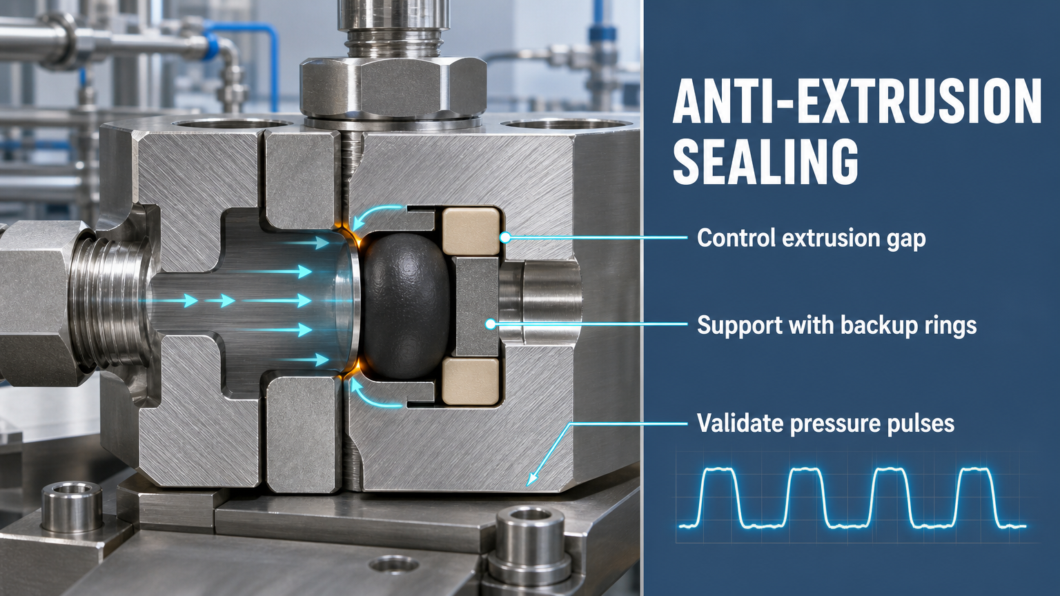
Fluid pressure pushes the O-ring toward the low-pressure side. If the clearance gap is large enough relative to the seal material and support condition, part of the O-ring enters the gap. Continued pressure can form an extrusion tail; repeated pressure changes can cut or nibble that tail and create a progressive leakage path.
Extrusion is not the same as compression set, swelling, chemical degradation, surface damage or thermal softening, although these mechanisms can interact. Compression set reduces recovery after long compression. Swelling changes dimensions and properties after fluid exposure. Thermal softening reduces resistance to deformation. A damaged groove edge can cut a seal even when the calculated gap is acceptable.
Pressure direction matters because the low-pressure side determines where the seal is driven. Pressure pulses add repeated deformation, while temperature changes alter both the seal and hardware dimensions. The final design check must use maximum pressure, maximum temperature, worst manufacturing tolerance and the intended pressure-cycle frequency.
Gap Control and Gland Design
The sealing gland is a tolerance system. Radial and axial extrusion gaps, groove width, groove depth, seal squeeze, gland fill, seal stretch, corner radius, surface roughness and hardware tolerance must be evaluated together. A larger gap generally increases extrusion risk, but reducing the gap alone does not guarantee reliability if the seal is over-compressed or damaged during assembly.
Higher hardness can improve resistance to extrusion, but it may reduce low-pressure conformability and increase installation force. Excessive squeeze can increase friction, heat and assembly damage. Excessive gland fill can amplify thermal expansion and pressure-related compression. The actual gap must be checked at the worst combination of pressure, temperature and dimensional variation, not only at nominal room-temperature dimensions.
Worst-case gap control must include the largest hardware clearance, the lowest effective seal stiffness, the highest pressure differential and the maximum temperature-induced dimensional change. It should also consider whether pressure direction reverses during operation. A design that is safe in one direction may require a second backup ring or a different gland arrangement when the pressure path changes.
Anti-Extrusion Design and Material Selection
A standard O-ring may be sufficient when pressure, gap and temperature are controlled. A backup ring is considered when the available clearance exceeds the validated capability of the primary seal. PTFE backup rings can provide low-friction support but may creep or migrate if fit and support are inadequate. PEEK rings can provide higher stiffness in selected conditions, but their chemical, temperature, tolerance and installation limits must be verified.
Dual backup rings can support pressure reversal or bidirectional service. Filled-PTFE rings may offer a balance of friction and stiffness depending on the compound. A dual-seal structure can add leakage protection, but it requires more space, inspection and pressure management. FKM, FFKM and EPDM primary seals remain compound- and chemistry-dependent; PEEK and PTFE support parts are not universal solutions.
Selection must include pressure, temperature, chemical medium, hardness, compression behavior, extrusion resistance, swelling, permeation, particle generation, friction and maintenance. A support ring can reduce extrusion while creating a new stress concentration or assembly risk if the dimensions are incorrect.
The primary seal and backup ring should be selected as a pair. Their clearances, thermal expansion, hardness and chemical response must remain compatible through assembly, operation and maintenance. A rigid support ring cannot correct a gland that is dimensionally wrong or a seal that has already lost recovery.
Static, Dynamic and Pressure-Pulse Sealing
Static manifold sealing, reciprocating sealing, rotary sealing, pressure-pulse sealing and thermal-cycle sealing impose different requirements. A static seal may not tolerate the shear and friction of a moving interface. A dynamic seal may need different surface finish, lubrication control and support than a stationary manifold seal.
Pressure-pulse service is especially important because a seal can pass a static pressure-hold test yet fail after repeated transient deformation. The pulse amplitude, frequency, temperature and pressure direction determine the support demand. Thermal cycling changes gap, squeeze and material recovery. Qualification should therefore reproduce the intended motion and pressure history rather than relying on a single static result.
Testing, Failure Analysis and Maintenance
Validation should combine pressure-hold, high-pressure leakage, pressure-pulse, thermal-cycle, chemical-immersion, compression-set and extrusion-gap testing. The test record should identify material, hardness, seal size, groove dimensions, gap, pressure, temperature, pulse frequency, chemical medium, duration, leakage result and damage morphology.
Pressure-pulse validation should reproduce the amplitude, frequency, temperature and dwell pattern expected in service. The test should record leakage before, during and after pulsing, then compare the seal morphology with the measured pressure history. A static pass followed by progressive nibbling during pulses indicates a dynamic support problem rather than a simple assembly leak.
Post-test teardown should inspect extrusion tails, nibbling, cuts, cracks, hardening, softening, swelling, backup-ring deformation and groove-edge damage. The morphology should be correlated with pressure, gap, temperature, chemistry, cycle history and assembly condition. Microscopy can distinguish a torn extrusion tail from a chemically cracked or abraded surface.
Table I: High-Pressure O-ring Extrusion Risk Factors
|
Factor |
Local mechanism |
Expected local effect |
Failure risk |
Recommended control |
| Pressure | Drives seal into low-pressure gap | Higher deformation force | Extrusion or nibbling | Define pressure direction and limit |
| Temperature | Changes modulus, expansion and swelling | Reduced support or altered squeeze | Softening or leakage | Evaluate worst-case temperature |
| Extrusion gap | Provides path for seal movement | Higher local deformation | Seal damage | Control worst-case gap |
| Seal hardness | Changes deformation and recovery | Different contact behavior | Extrusion or poor sealing | Select hardness by condition |
| Compression | Creates contact stress | Too low or too high contact | Leakage or damage | Control squeeze and gland fill |
| Chemical exposure | Swelling, softening or degradation | Changed geometry and strength | Extrusion or cracking | Test actual medium |
| Pressure-cycle frequency | Repeats deformation | Accumulated local damage | Nibbled seal or fatigue | Test duty cycle and inspect |
Extrusion risk is controlled by the combined pressure, gap, temperature, hardness, compression, chemistry and cycle condition. A single parameter cannot define the complete design margin.
Table II: Anti-Extrusion Support Options
|
Support option |
Support mechanism |
Pressure capability |
Temperature or chemical boundary |
Assembly concern |
Best application |
Main limitation |
| Standard O-ring | Seal relies on material and gland support | Limited by gap and material | Compound dependent | Sensitive to gap and assembly | Controlled low-to-moderate pressure | No dedicated extrusion support |
| PTFE backup ring | Fills clearance gap with low-friction support | Improves gap resistance | Creep and temperature dependent | Orientation and fit | Static high-pressure service | May migrate or complicate assembly |
| PEEK backup ring | Rigid support against extrusion | High stiffness in selected conditions | Chemistry and temperature dependent | Tight tolerance and installation | High-pressure manifold support | Higher cost and geometry sensitivity |
| Dual backup rings | Supports both pressure directions | Useful when pressure reverses | Fit and thermal response dependent | More parts and interfaces | Bidirectional pressure or pulses | More assembly complexity |
| Filled-PTFE ring | Low-friction filled support | Improved support with selected fillers | Compound-specific | Particle and fit control | Guided support applications | Filler and creep limits |
| Dual-seal structure | Primary seal plus secondary barrier | Adds leakage protection | Requires compatible materials | More space and inspection | High-consequence service | Does not remove common gap failure |
Support rings reduce extrusion clearance but introduce fit, friction, thermal, chemical and assembly variables. The correct option depends on pressure direction, motion and maintenance conditions.
Table III: Gap and Gland Design Verification Matrix
|
Design parameter |
Required check |
Worst-case condition |
Failure risk |
Verification method |
Acceptance basis |
| Radial gap | Measure hardware clearance | Maximum tolerance and temperature | Extrusion path | Dimensional inspection and calculation | Project-defined worst case |
| Axial gap | Check end clearance and pressure direction | Maximum stack-up | Local extrusion or nibbling | Drawing review and measurement | Approved tolerance stack |
| Groove depth | Confirm squeeze and fill | Minimum/maximum tolerance | Leakage or over-compression | Measurement and assembly check | Design calculation |
| Groove width | Confirm gland fill | Seal expansion and pressure | Thermal or pressure damage | Inspection and calculation | Defined fill envelope |
| Seal squeeze | Verify compression ratio | Temperature and assembly tolerance | Low contact or friction damage | Cross-section and test | Project criterion |
| Hardware tolerance | Combine shaft, bore and groove variation | Worst stack-up | Unexpected gap or squeeze | Tolerance analysis | Released drawing limits |
| Surface finish | Check sealing surfaces and edges | Machining and damage condition | Leak path or abrasion | Profilometry and visual inspection | Specified finish and edge condition |
Gap and gland verification should use the worst combination of pressure, temperature and manufacturing tolerance. Any numerical acceptance value must state material, hardness, geometry and test condition.
FMEA Risk Analysis
A high-pressure manifold FMEA should distinguish extrusion, nibbling, chemical swelling, compression set, backup-ring deformation, pressure-pulse fatigue, groove damage and assembly error. The system effect depends on the seal location, pressure boundary and consequence of flow loss or chemical release.
Table IV: High-Pressure Manifold Seal FMEA and RPN Analysis
|
Failure mode |
Cause |
Local effect |
System effect |
Detection method |
Illustrative RPN |
Corrective action |
| O-ring extrusion | Excessive gap or pressure | Seal enters clearance | Leakage or pressure loss | Teardown and leak test | 175 | Control gap and support |
| Seal nibbling | Repeated pressure cycling | Cuts or missing seal material | Progressive leakage | Microscopy and pulse test | 180 | Reduce gap and cycle stress |
| Chemical swelling | Incompatible medium | Geometry and hardness change | Leakage or extrusion | Immersion and dimensional test | 170 | Validate material and medium |
| Compression set | Long dwell or thermal exposure | Reduced recovery | Low-pressure leakage | Compression-set and leak test | 155 | Review compound and squeeze |
| Backup-ring deformation | Wrong material, gap or load | Support loss or particle risk | Repeat extrusion | Inspection and dimensional check | 160 | Review ring design and fit |
| Incorrect assembly | Twist, cut or wrong orientation | Immediate local defect | Early field leakage | Assembly inspection and pressure test | 190 | Controlled installation procedure |
| Pressure-pulse fatigue | High pulse frequency or amplitude | Accumulated deformation | Cycle-dependent failure | Pulse test and trend | 185 | Define pulse envelope and validate |
| Groove damage | Sharp edge, scratch or tool damage | Local leak path | Manifold leakage | Visual and surface inspection | 165 | Protect and inspect groove |
| Insufficient inspection | No teardown or morphology review | Mechanism remains unknown | Repeat failure | Post-test audit | 150 | Require failure-analysis record |
All RPN values are illustrative engineering assessments, not universal safety limits, certification results or field-failure statistics. Project scoring should define Severity, Occurrence and Detection and convert high-priority items into design and test controls.
Conclusion
High-pressure manifold sealing is not solved by choosing a harder or more expensive seal alone. Reliability depends on seal material and hardness, pressure, temperature, extrusion gap, groove geometry, backup support, surface finish, manufacturing tolerance, assembly control and verification method.
A reliable design provides controlled extrusion clearance, stable contact stress, chemical compatibility, pressure-pulse resistance, thermal-cycle stability, inspectable failure behavior and verifiable assembly quality. The final margin must be demonstrated under the actual pressure, temperature, chemical and cycle envelope.
Engineering FAQ
Q:What causes O-ring extrusion in a high-pressure manifold?
A:Pressure drives the O-ring toward the low-pressure clearance gap. Extrusion becomes likely when the gap, temperature, material deformation and support condition exceed the validated design envelope.
Q:How does extrusion gap affect seal reliability?
A:A larger gap provides more space for seal movement and generally increases extrusion risk. The worst-case gap must combine hardware tolerances, temperature and pressure conditions.
Q:When is a backup ring required?
A:A backup ring is considered when pressure, gap, temperature, material or pressure cycling creates an extrusion risk that the O-ring and gland cannot safely control alone.
Q:How should PTFE and PEEK backup rings be compared?
A:Compare stiffness, creep, temperature, chemical compatibility, friction, installation, particle risk and tolerance. Neither material is universally best for every manifold.
Q:What is the difference between extrusion, compression set and chemical swelling?
A:Extrusion is movement into a clearance gap; compression set is loss of recovery after compression; swelling is a material-chemistry interaction that changes dimensions and properties.
Q:Which tests are necessary to validate a high-pressure manifold seal?
A:Use pressure hold, high-pressure leak, pressure-pulse, thermal-cycle, chemical-immersion, compression-set, extrusion-gap and post-test teardown methods under defined conditions.
Post time: Aug-21-2026