
Executive Summary
High-pressure hydrogen valve sealing is a coupled materials, geometry and pressure-history problem. Valve architecture, elastomer formulation, seal geometry, extrusion-gap control, compression, pressure cycling, temperature, surface condition, assembly quality and leak verification determine whether the high-pressure side remains isolated from the low-pressure side and vent path.
Hydrogen permeation, external leakage, internal valve leakage, interface leakage and rapid-decompression damage are different observations. Permeation is molecular transport through an elastomer; external leakage requires a path to the environment; internal leakage is unintended flow across a valve boundary. Rapid depressurization can damage a chemically compatible elastomer. A static hold or single immersion result cannot represent long-term hydrogen-cycle reliability.
High-Pressure Hydrogen Valve Sealing Architecture
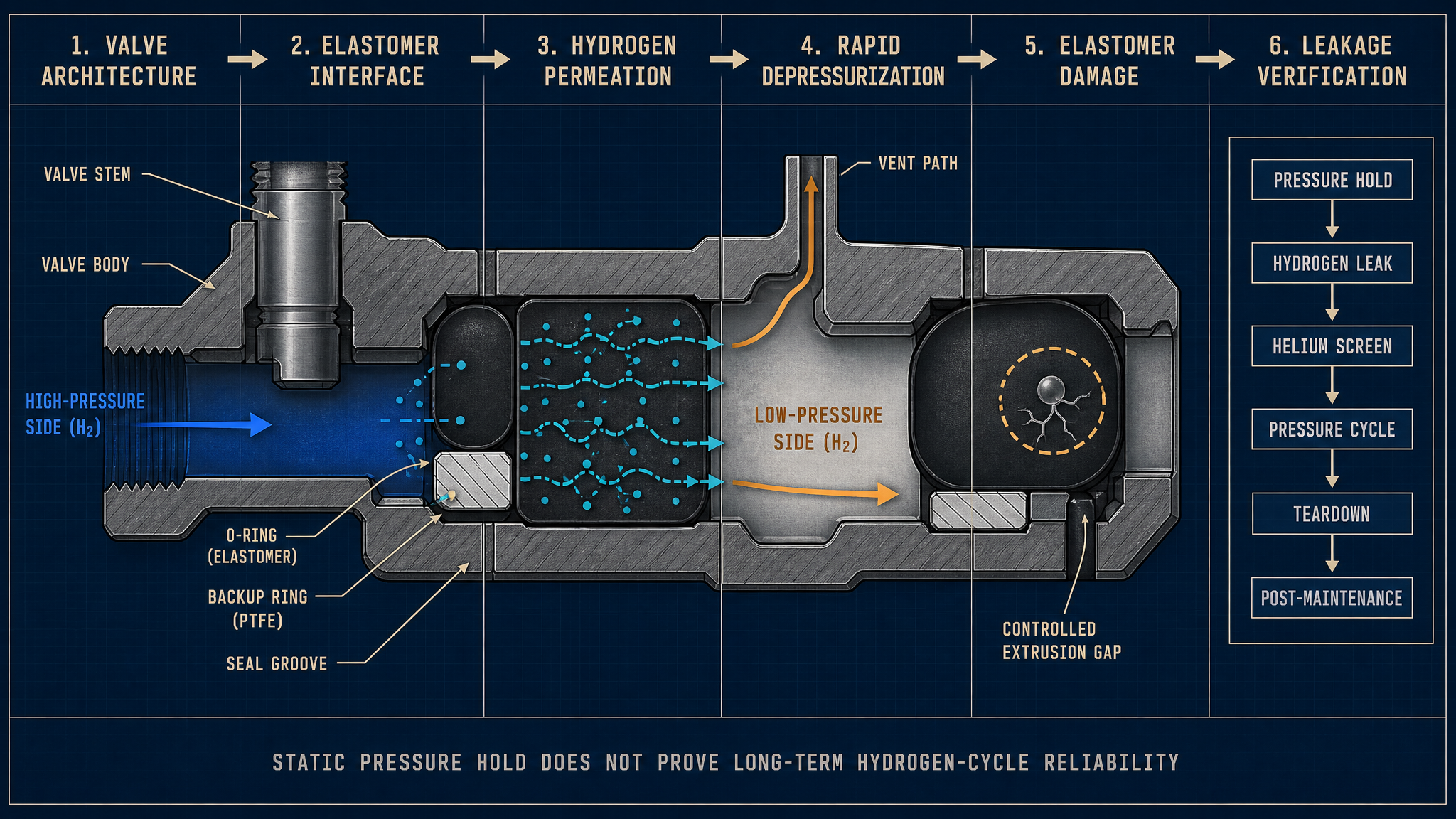
A hydrogen-service valve combines a valve body, stem, seat, O-ring, backup ring, seal groove, retaining structure and actuator interface. The sealing boundaries divide the high-pressure side, low-pressure side and vent or discharge path. Static body seals close fixed joints. Dynamic stem seals maintain contact while the stem reciprocates or rotates. The valve-seat seal closes the principal flow path and must preserve contact after pressure changes, contamination and repeated actuation.
Seal grooves control compression, support and available extrusion clearance. Backup rings support the elastomer where differential pressure could drive it into a gap, but ring orientation, edge condition and fit become part of the sealing system. The counterface is equally important: stem runout, scratches, surface roughness and contamination can interrupt contact even when the elastomer is dimensionally correct. The actuator interface adds movement, force and alignment variation that static seals do not experience.
Table I: High-Pressure Hydrogen Valve Sealing Functions and Risks
|
Valve or seal component |
Main sealing function |
Hydrogen-related stressor |
Typical risk |
Verification focus |
| Valve-body static seal | Close fixed joints | Pressure, exposure time | Compression-set loss, interface leakage | Pressure hold and dimensions |
| Dynamic stem seal | Seal moving stem | Motion, pressure, friction | Stem wear, stick-slip, leakage | Actuation and leak trend |
| Valve-seat seal | Isolate high and low sides | Differential pressure, particles | Seat wear, internal leakage | Seat leak and surface check |
| O-ring and groove | Maintain contact pressure | Hydrogen permeation, temperature | Swelling, hardening, set loss | Material and groove inspection |
| Backup ring | Support elastomer | Extrusion gap, pressure ratio | Displacement, edge damage | Orientation and gap check |
| Vent boundary | Control discharge path | Pressure reduction, contamination | External or interface leakage | Vent isolation test |
The component label does not define the risk. One elastomer can behave differently in a static body seal, moving stem seal and pressure-assisted seat because compression, motion, support and counterface conditions differ.
Hydrogen Permeation and Leakage Mechanisms
Hydrogen can diffuse into and permeate through an elastomer under a concentration or pressure gradient. Permeation depends on formulation, temperature, pressure, thickness, exposure time and geometry. It may create a gradual detector response without an open crack or visible flow. Diffusion describes transport within the material; permeation describes passage through it and out the opposite surface.
External hydrogen leakage requires a connected path from the pressurized boundary to the environment. Internal valve leakage is flow from the high-pressure side toward the low-pressure side or vent path. Interface leakage can result from compression loss, a scratch, contamination, excessive clearance or a discontinuous sealing line. A pressure-dependent step may support a discrete path, while a slow signal may reflect permeation, background, sampling effects or sensor or test-system error. Interpretations require controlled pressure, temperature, sampling location and calibration records.
Thickness and contact pressure affect the signal, but no fixed permeability or leakage limit applies to every valve. Diagnosis should combine pressure response, hold time, temperature, detector behavior, seal dimensions and surface inspection. “Hydrogen is small” is not an adequate failure analysis, and incompatibility requires evidence of chemical or physical degradation.
Depressurization Cycling and Elastomer Damage
The critical sequence is pressure increase, pressure hold, controlled or rapid depressurization, dwell and repetition. Hydrogen may dissolve or diffuse into the elastomer during the high-pressure period. If external pressure falls faster than internal gas can escape, local internal pressure can produce blistering, internal cracking, local separation or permanent deformation. This mechanism is commonly discussed as rapid gas decompression or explosive decompression damage, but its severity is configuration-dependent.
Risk depends on formulation, seal cross-section, groove restraint, pressure range, low-side condition, pressure ratio, dwell time, temperature, depressurization rate and cycle history. A large section may retain gas longer; a sharp corner or unsupported region may concentrate stress. Repeated cycles can turn a small defect into a leakage path even if the first cycle shows no external sign. One rapid-decompression test cannot prove all service sequences, and no fixed rate, ratio or cycle count is universal.
The post-test distinction matters. Blistering or cracking indicates internal damage; compression-set loss indicates permanent recovery loss; extrusion indicates displacement into a gap; swelling or hardening indicates a material-state change. These may coexist, but they require different corrective actions.
Table II: Permeation, Depressurization and Extrusion Influence Matrix
|
Stress factor |
Primary effect |
Secondary effect |
Potential failure mode |
Required measurement |
Main limitation |
| Hydrogen exposure | Diffusion and permeation | Property change over time | Permeation, hardening | Pressure, temperature, detector trend | Formulation-specific |
| Pressure hold | Internal gas uptake | Contact-pressure loading | Delayed decompression damage | Pressure and dwell history | Does not show cycle effect |
| Rapid depressurization | Internal pressure mismatch | Blister or crack growth | Rapid-decompression damage | Rate, pressure ratio, teardown | Sequence-specific |
| Temperature change | Modulus and dimension shift | Permeability change | Thermal-cycle leakage | Temperature history and leakage | Does not isolate pressure damage |
| Extrusion gap | Elastomer displacement | Edge damage and wear | Extrusion, interface leakage | Gap, support and imprint | Geometry-dependent |
| Stem movement | Friction and wear | Torque or force variation | Stem-seal leakage | Motion, force, surface track | Dynamic only |
The matrix is a planning aid rather than a universal qualification standard. Each test must retain the valve architecture, seal material, pressure history, low-side condition and measurement method.
Compression, Extrusion and Valve Motion
Compression creates contact pressure, but the margin depends on groove fill, surface finish, clearance and recovery. Too little compression can leave a path; too much can increase friction, heat, set and damage. Differential pressure can push elastomer toward the extrusion gap. If support is incomplete, it may displace, tear or develop a damaged edge.
Backup rings reduce extrusion risk only when material, orientation, fit and edge condition match the groove. A displaced or contaminated ring can create a local gap. Temperature-dependent clearance can change support. In a dynamic stem seal, friction and stick-slip add loading. Stem runout, eccentricity, scratches and roughness create wear, while pressure changes alter contact. Groove, ring, gap and counterface must be evaluated together.
Elastomer Compatibility and Long-Term Degradation
HNBR, FKM, FFKM, EPDM, PTFE-based elements, filled polymer backup rings and low-permeation compounds may suit different hydrogen conditions. Behavior remains conditional on formulation, temperature, pressure, dwell time, compression, geometry, cleaning and depressurization history. Low permeation may coexist with limited rapid-decompression resistance; useful temperature capability may still create friction or compression set.
Swelling can raise groove fill and friction; shrinkage can reduce contact pressure. Hardening reduces compliance and recovery; softening increases extrusion and wear. Cleaning residues and particles can alter the sealing line. Coated or hardened metal surfaces reduce wear only when integrity, roughness, alignment and counterface behavior are controlled. No material or treatment is universal.
Inspection, Testing and Maintenance
- Static pressure-hold testing checks one boundary condition. Hydrogen leak detection measures a selected sampling arrangement. Helium testing can screen fine paths under helium conditions, but does not represent long-term hydrogen exposure. Permeation evaluation separates material transport from open-path leakage when thickness, pressure, temperature and exposure are controlled.
- Pressure-cycle testing examines repeated loading. Controlled-depressurization testing studies a release sequence, while rapid-decompression testing challenges the elastomer against faster pressure reduction. Temperature cycling exposes changes in modulus, dimensions and recovery. Actuation cycling adds stem motion, friction and force variation. Dimension, groove, gap, surface and teardown inspections help identify the origin.
- Teardown should record blistering, cracking, compression set, extrusion, uneven wear, stem or seat damage, scratches, contamination and seal orientation. After replacement, verify material identity, direction, groove cleanliness, ring condition, compression, clearance, surface condition and applicable static, dynamic, pressure-cycle and depressurization tests.
Table III: High-Pressure Hydrogen Valve Seal Verification Guide
|
Test or inspection |
Test purpose |
Key variable |
Detectable issue |
Suitable stage |
Main limitation |
| Static pressure hold | Check defined boundary | Pressure, time, temperature | External or seat leakage | Production and validation | Does not prove cycling |
| Hydrogen leak test | Detect hydrogen release | Sampling, calibration, pressure | External leakage | Commissioning and service | Sensor and background effects |
| Helium leak test | Screen fine paths | Helium pressure, fixture | Small interface path | Component and validation | Not long-term hydrogen service |
| Permeation evaluation | Separate material transport | Thickness, pressure, temperature | Permeation trend | Material and design | Not a complete valve test |
| Pressure-cycle test | Examine repeated loading | Pressure history, cycle count | Pressure-cycle leakage | Reliability validation | Sequence-specific |
| Rapid-decompression test | Challenge elastomer release | Rate, ratio, dwell, temperature | Blistering, cracking | Material and valve validation | One sequence only |
| Actuation-cycle test | Evaluate moving seal | Motion, force, surface track | Stem wear, friction, leakage | Design and service analysis | Does not isolate chemistry |
| Teardown inspection | Identify physical origin | Dimensions, surfaces, morphology | Set, extrusion, cracks | Failure analysis and service | Destructive and local |
Each record should retain valve identity, seal material and geometry, groove and backup-ring condition, extrusion gap, pressure and low-side history, temperature, depressurization rate, dwell time, cycle count, leakage result, actuation force, hardness, assembly history and teardown observations.
Data Interpretation and Maintenance Planning
A useful record connects valve architecture with seal section, groove dimensions, ring condition, extrusion gap, hydrogen pressure, low-side pressure, temperature, pressure-rise rate, depressurization rate, dwell time, cycle count, leakage, actuation force, hardness and morphology. This prevents a detector signal being assigned to permeation or ageing before test-system, surface, clearance and assembly causes are reviewed.
Maintenance may be calendar-, pressure-cycle-, depressurization-history-, leakage-trend-, actuation-force-, condition- or risk-based. Post-repair requalification should confirm alignment, cleaning, seal direction, ring support, compression, clearance and pressure and motion tests. Laboratory cycle counts and single-test life results are not a universal service life for vehicles, storage banks or refueling equipment.
FMEA Risk Analysis
Table IV: High-Pressure Hydrogen Valve Sealing FMEA and RPN Analysis
|
Failure mode |
Cause |
Local/System effect |
Detection method |
RPN |
Corrective action |
| Hydrogen permeation | Material transport under pressure gradient | Detector signal; possible misclassification | Controlled permeation evaluation | 144 | Confirm material, thickness and baseline |
| Rapid-decompression damage | Internal gas release lags pressure reduction | Blister, crack and later leakage | Depressurization test and teardown | 240 | Qualify sequence and improve restraint |
| Seal extrusion | Excessive gap or inadequate support | Damaged edge; interface leakage | Gap inspection and imprint | 216 | Control clearance and backup ring |
| Compression-set loss | Pressure, temperature and time history | Lower recovery and contact pressure | Dimension and cycling trend | 180 | Review material and compression margin |
| Seal hardening or softening | Exposure, ageing or cleaning condition | Reduced compliance or higher wear | Hardness and morphology comparison | 168 | Control formulation and cleaning |
| Stem or seat wear | Motion, roughness or contamination | Dynamic or internal leakage | Force trend and surface inspection | 192 | Improve counterface and cleanliness |
| Incorrect orientation or contamination | Assembly error or residue | Local gap, friction or early leakage | Assembly audit and teardown | 210 | Add traceability and clean assembly |
| Pressure- or temperature-cycle leakage | Repeated load and thermal change | Intermittent or progressive leakage | Cycle history and leakage trend | 225 | Validate representative cycles |
| Inadequate post-maintenance verification | Release after limited test | Latent leakage remains in service | Requalification audit | 252 | Require static, dynamic and decompression checks |
The RPN values are illustrative engineering risk rankings, not field statistics or experimental results. They support prioritization and do not replace design evidence, test records or failure analysis.
Conclusion
High-pressure hydrogen valve sealing depends on hydrogen permeation, formulation, geometry, extrusion-gap control, compression, ring support, stem motion, surface condition, pressure history, depressurization history and assembly quality. Permeation, external and internal leakage, interface leakage, rapid-decompression damage, compression-set loss, extrusion, blistering and cracking are distinct mechanisms.
Reliable verification must combine material evaluation, static and dynamic leakage testing, pressure cycling, controlled or rapid depressurization, temperature cycling, actuation-force monitoring, dimensional inspection and post-test teardown. No single elastomer, backup ring or surface treatment eliminates every high-pressure hydrogen sealing risk. Maintenance reliability is established only after material identity, orientation, cleanliness, compression, clearance and relevant requalification tests are confirmed.
Engineering FAQ
Q:How does hydrogen permeation affect high-pressure valve seals?
A:Hydrogen can diffuse into and through an elastomer, creating a transport signal without an open leakage path. The observed behavior depends on formulation, thickness, pressure, temperature, exposure time and geometry. Permeation should therefore be separated from interface leakage and confirmed under controlled conditions.
Q:Why can rapid depressurization damage an elastomer seal?
A:Gas retained or dissolved in the elastomer may not escape as quickly as external pressure falls. The resulting internal pressure can cause blistering, cracking, local separation or permanent deformation. The risk depends on the material, cross-section, pressure history, temperature, restraint and release sequence.
Q:What is the difference between hydrogen permeation and external leakage?
A:Permeation is molecular transport through the material. External leakage is flow through a connected path from the pressurized boundary to the environment. A slow detector response may be consistent with permeation, while a pressure-dependent step change may support an interface, seat or structural path; controlled testing is required.
Q:How do extrusion gap and backup rings affect hydrogen valve sealing?
A:An excessive extrusion gap allows the elastomer to move into unsupported space under differential pressure. A correctly fitted backup ring supports the seal, but an incorrect orientation, damaged edge, contamination or gap mismatch can create another failure path. Gap and ring condition must be inspected together.
Q:Which tests are needed after replacing a high-pressure hydrogen valve seal?
A:Confirm material identity, seal direction, groove cleanliness, backup-ring condition, compression, extrusion clearance and counterface condition. Then repeat the applicable static, hydrogen or helium, dynamic actuation, pressure-cycle and depressurization checks before release.
Q:Can one elastomer suit every hydrogen pressure and decompression cycle?
A:No universal material choice can be assumed. Compatibility, permeation, rapid-decompression resistance, compression set, friction, temperature and geometry must be evaluated for the defined valve and pressure history. Assembled-valve testing remains necessary after material screening.
Post time: Aug-31-2026