
Executive Summary
High-temperature furnace tube end sealing is a coupled mechanical, thermal and contamination-control problem. The boundary must contain process gas while accommodating thermal expansion, pressure difference, tube-end movement and repeated heating and cooling. Reliable performance depends on tube-end geometry, seal compression, flange alignment, material compatibility, surface condition, thermal-cycle history and maintenance repeatability.
A single pressure-hold or leak-test result describes one defined condition. It does not by itself prove that contact pressure remains continuous after heat soak, that a flange has not distorted, or that particles are not being released from a damaged interface. Gas tightness, thermal-cycle resistance and particle control must therefore be verified as related but separate performance questions.
Furnace Tube End-Seal Architecture
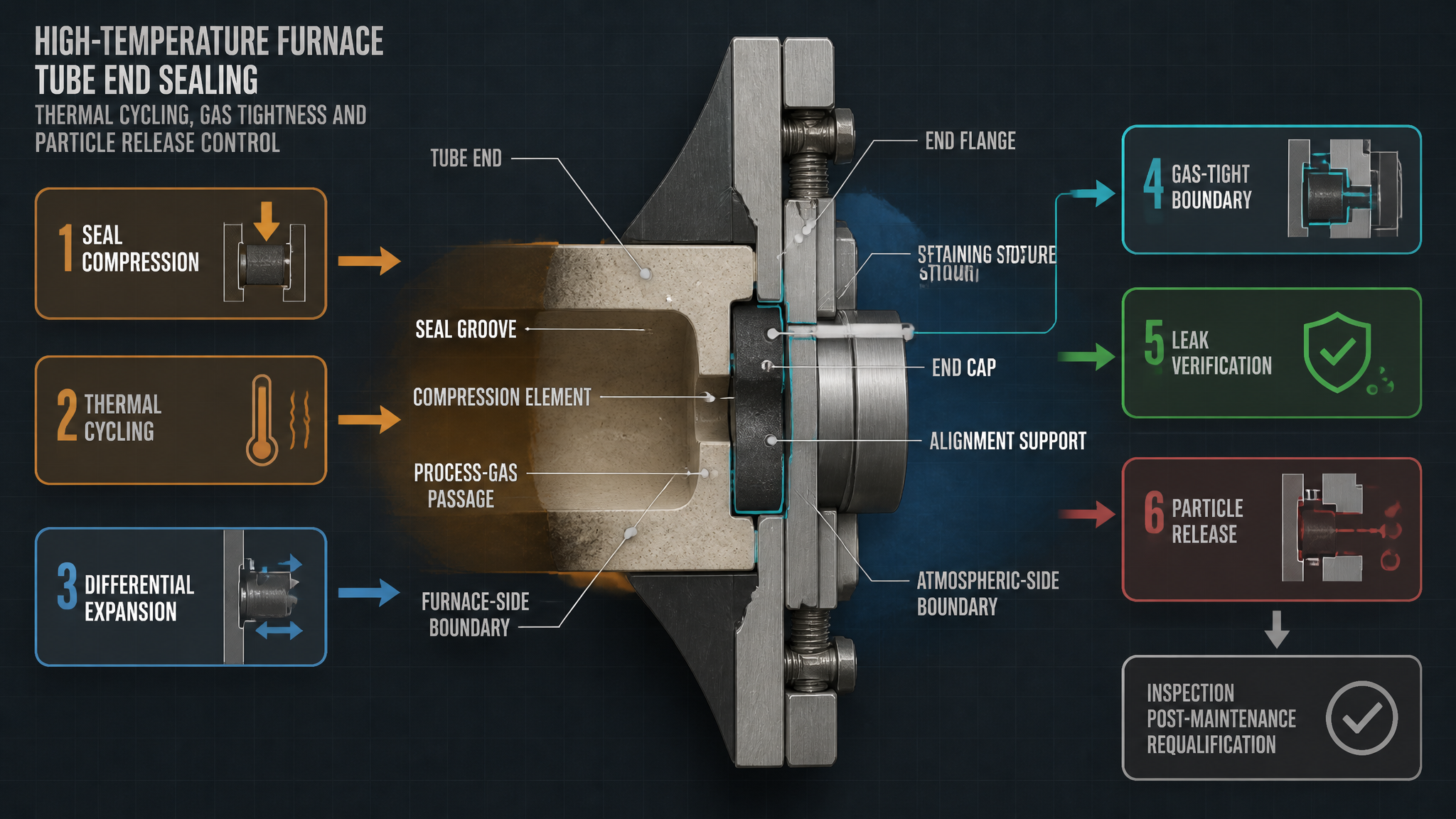
A furnace tube end seal normally combines the tube end, end flange, end cap, seal carrier, seal groove, compression element, retaining structure and alignment supports. The process-gas passage must be separated from the atmospheric-side boundary and the furnace-side boundary without creating uncontrolled contact at the tube end. Depending on the design, the primary barrier may be a static compression seal, a gasketed interface, a ceramic contact, a metal sealing interface or a combination of these features.
The seal is governed by more than the sealing material. Tube-end roundness, end-face flatness, flange parallelism, groove condition, retaining force and support stiffness determine whether contact is continuous. Temperature gradients and pressure differences add load while the structure is constrained. A static seal, a compressed gasket and a ceramic or metal contact should be evaluated according to their actual load path rather than treated as interchangeable solutions.
Table I: Furnace Tube End-Seal Failure Mechanisms
|
Failure mechanism |
Primary stressor |
Local physical effect |
Typical symptom |
Recommended validation |
| Insufficient compression | Low retaining force or tolerance stack | Discontinuous contact | External leak | Compression and leak test |
| Excessive compression | Over-tightening or poor stop | Crushing or extrusion | Torque rise or debris | Dimensional and teardown review |
| Expansion mismatch | Different thermal expansion | Contact-pressure shift | Leak after heating | Thermal-cycle leak test |
| Tube-end deformation | Thermal gradient or support load | Local gap or tilt | Localized leakage | Flatness and alignment check |
| Flange distortion | Uneven load or heat | Nonuniform sealing line | Pressure drift | Surface mapping and cycle test |
| Seal degradation | Heat, gas or time | Hardening, softening or cracking | Leakage or particles | Material and morphology review |
| Surface damage | Scratching, flaking or contact | Leakage path or debris | Particle increase | Microscopy and cleanliness check |
| Misalignment | Incorrect assembly or support | Edge loading | Repeated-cycle leakage | Runout and alignment check |
The table separates local physical mechanisms from symptoms. The same leakage signal may result from different causes and requires evidence from inspection, operation and teardown.
Sealing Mechanism and Compression Control
The compression element must maintain sufficient contact pressure and seal-line continuity across the expected temperature and pressure range. Groove geometry, end-face flatness, surface roughness, flange parallelism and retaining force determine how the load is distributed. Pressure-assisted sealing can improve contact in one operating direction, but it does not remove the need to control initial assembly and structural alignment.
Insufficient compression can leave a local micro-leak path, especially where particles or a damaged surface interrupt the interface. Excessive compression can damage the seal, promote extrusion, raise assembly friction and increase particle generation. A tube-end scratch, trapped foreign particle or locally warped flange can create a path even when the assembly appears fully closed. Closing the end cap or reaching a specified torque therefore does not automatically prove uniform contact across the complete sealing line.
Thermal Cycling and Expansion Mismatch
During a heating ramp, heat soak and cooling ramp, the furnace tube, flange, end cap, seal and retaining structure may expand at different rates. The resulting differential movement can temporarily increase or reduce contact pressure. A temperature gradient across the tube end may produce local tilt or flange distortion, while repeated start-stop operation can accumulate fatigue, creep and stress relaxation.
Long high-temperature exposure may change the seal through hardening, softening, oxidation, chemical attack, volatile release or loss of elastic recovery. The same cycle may also change the tube-end surface, coating condition or flange geometry. A successful single heating or cooling event is not evidence of long-term cycle stability. Thermal-cycle evaluation should record heating rate, cooling rate, soak duration, gas atmosphere, pressure condition and cycle history so that a leakage change can be related to a defined thermal and mechanical state.
Table II: Thermal Cycling, Pressure and Interface Influence Matrix
|
Stress factor |
Primary effect |
Secondary effect |
Potential failure mode |
Required measurement |
Main limitation |
| Heating ramp | Differential expansion | Compression shift | Thermal-cycle leakage | Temperature history | Local gradient may be missed |
| Heat soak | Creep and aging | Loss of recovery | Compression-set loss | Soak and material record | Time dependence |
| Cooling ramp | Contraction mismatch | Temporary gap | Internal or external leak | Leak during cooling | Sensor response delay |
| Pressure differential | Load on boundary | Contact redistribution | Seal-line opening | Pressure and leak trend | Depends on geometry |
| Flange movement | Local tilt or warp | Edge loading | Local leakage | Flatness and alignment | Requires mapping |
| Repeated cycling | Fatigue and relaxation | Debris accumulation | Particle generation | Cycle count and particles | Field history varies |
Thermal, pressure and interface records should be interpreted together. A temperature trace without contact, leak and particle evidence cannot identify the complete failure mechanism.
Gas Tightness and Leakage Verification
Pressure-hold testing establishes whether a defined pressure boundary remains stable for a defined time. Vacuum hold or pressure-rise testing can reveal a changing boundary in a vacuum or low-pressure configuration. Helium leak testing provides high-sensitivity local leakage information when the test setup, background and calibration are controlled. Positive-pressure and differential-pressure testing should reflect the actual direction and magnitude of service loading.
Thermal-cycle leak testing is necessary when heating and cooling can change contact pressure or flange geometry. Local leak detection helps locate a boundary defect, while gas composition monitoring can help distinguish external leakage from internal gas mixing. Each method has a different objective and limitation; a static result should not be presented as proof of long-term thermal-cycle or particle performance. Specific leak limits must be confirmed from the furnace design, process gas, pressure class and equipment specification rather than treated as universal values.
Particle Release and Contamination Control
Particles at a furnace tube end may originate from seal wear, surface flaking, oxide scale, coating damage, ceramic chipping, metal contact, assembly friction, thermal-fatigue cracking, seal extrusion, foreign particles trapped at the face, cleaning residue or improper maintenance. Repeated thermal cycling can enlarge a crack, loosen a scale or change contact enough to convert a small defect into a particle source.
Particle control must be analyzed with thermal movement and contact pressure. Excessive compression can increase friction and material damage; insufficient compression can permit micro-motion and unstable contact. Released particles may enter the process-gas path, the furnace tube or a sensitive process region. Low particle release, low outgassing and long-term gas tightness are separate claims requiring separate evidence. A cleaned component can generate new particles if the assembly introduces edge damage, residue or misalignment.
Material Compatibility and High-Temperature Degradation
Ceramic sealing elements, metal seals, high-temperature elastomers, graphite-based materials, mica or layered materials, high-temperature polymers, coated metal surfaces and ceramic or refractory interfaces each have different temperature boundaries and failure mechanisms. Selection should compare thermal expansion, gas compatibility, oxidation behavior, compression stability, creep, volatile release, particle generation and cleaning tolerance.
A material that remains chemically stable may still be unsuitable if its recovery or compression stability is insufficient. A hard interface may resist some wear but be vulnerable to chipping or brittle damage. A compliant material may accommodate surface variation but experience compression set, extrusion or outgassing. These trade-offs must be evaluated against the actual furnace atmosphere, pressure, thermal cycle and contamination consequence. No material should be described as the universal best solution for every furnace tube end.
Inspection, Testing and Maintenance
Inspection should begin with tube-end geometry, end-face flatness, seal-groove condition, surface roughness, compression condition and alignment. Pressure-hold and helium leak tests establish gas-tightness evidence; thermal-cycle testing examines stability after defined heating, soak and cooling conditions; particle monitoring and surface-cleanliness inspection address contamination behavior. Post-test teardown and damage morphology analysis are needed when leakage, flaking, cracking, extrusion or particles are detected.
Visual inspection cannot replace gas-tightness testing. A single leak test cannot replace thermal-cycle verification, and a successful thermal cycle cannot automatically prove particle control. After replacement, the tube end, flange, groove, seal, retaining structure and gas path should be cleaned and assembled under a documented procedure. Requalification should include the relevant pressure test, leak test, thermal history and particle or cleanliness check before the equipment returns to production.
Table III: Furnace Tube Seal Gas-Tightness and Particle Verification Guide
|
Test or inspection |
Test purpose |
Key variable |
Detectable issue |
Suitable stage |
Main limitation |
| Visual inspection | Identify visible damage | Flaking, cracks, residue | Surface defect | Every service event | Cannot prove tightness |
| Flatness and groove check | Confirm contact geometry | Flatness and groove state | Local gap or tilt | Pre-assembly | Needs suitable gauge |
| Pressure-hold test | Verify static boundary | Pressure and time | Pressure loss | Assembly baseline | One thermal state |
| Helium leak test | Locate small boundary leaks | Leak signal and setup | Local gas path | Qualification or repair | Background dependent |
| Thermal-cycle leak test | Check post-cycle stability | Ramp, soak and cooling | Contact or distortion change | Design validation | Requires representative cycle |
| Particle monitoring | Detect released solids | Size, count and location | Particle generation | Cleanliness validation | Sampling may miss events |
| Teardown analysis | Confirm damage source | Morphology and residue | Crack, wear or extrusion | Failure analysis | Destructive |
| Cleaning verification | Confirm post-service state | Residue and handling record | Recontamination | Maintenance release | Process-specific |
No single method represents complete reliability. The required record should connect geometry, compression, gas condition, temperature history, leakage, particles, cleaning and physical evidence.
Data Interpretation and Maintenance Planning
Maintain records for furnace tube material, end-flange material, seal material, seal geometry, groove dimensions, compression condition, surface condition, alignment, temperature history, heating and cooling rate, soak time, pressure, gas composition, cycle count, leakage trend, particle result, cleaning history, assembly history, teardown findings and corrective action.
Maintenance may be calendar-based, cycle-based, condition-based, leakage-trend-based, particle-trend-based, thermal-history-based or risk-based. Replacement intervals should reflect the actual furnace atmosphere, cycle severity, contamination consequence and monitoring capability. Laboratory cycle counts must not be converted directly into a fixed field life for every furnace design.
FMEA Risk Analysis
The RPN values below are illustrative engineering risk rankings, not field statistics or experimental results.
Table IV: Furnace Tube End-Seal FMEA and RPN Analysis
|
Failure mode |
Cause |
Local effect |
System effect |
Detection method |
RPN |
Corrective action |
| Insufficient compression | Tolerance stack or low force | Discontinuous contact | External gas leak | Compression and leak test | 185 | Review load path and assembly |
| Excessive compression | Over-tightening or poor stop | Crushing or extrusion | Damage and particles | Torque and teardown review | 175 | Control stop and force |
| Thermal expansion mismatch | Different material movement | Contact shift | Thermal-cycle leakage | Cycle leak and alignment test | 190 | Review materials and compliance |
| Tube-end deformation | Gradient or support load | Local gap | Internal or external leak | Flatness mapping | 180 | Correct support and geometry |
| Flange distortion | Uneven load or heating | Nonuniform line | Pressure instability | Surface and cycle inspection | 180 | Improve load distribution |
| Compression-set loss | Heat and time | Reduced recovery | Persistent leakage | Material and compression review | 175 | Review service boundary |
| Seal hardening or cracking | Aging, oxidation or chemistry | Loss of conformity | Leak and particle release | Teardown morphology | 185 | Check compatibility and exposure |
| Surface flaking | Oxide, coating or thermal fatigue | Loose debris | Process contamination | Particle and surface inspection | 180 | Remove source and requalify |
| Misalignment | Incorrect assembly or support | Edge loading | Repeated-cycle leak | Alignment check | 170 | Correct assembly reference |
| Foreign particles at interface | Incomplete cleaning | Local gap or wear | Leakage and debris | Cleanliness and teardown | 175 | Improve cleaning control |
| Inadequate post-maintenance verification | Test scope too narrow | Hidden defect remains | Early recurrence | Requalification audit | 180 | Expand release criteria |
Corrective action should distinguish design, material, assembly and maintenance causes. Replacing the seal alone is insufficient when the tube end, flange, support or cleaning process remains defective.
Conclusion
High-temperature furnace tube end sealing must be evaluated as a complete thermal-mechanical and contamination-control boundary. Tube-end geometry, compression continuity, flange alignment, expansion mismatch, gas compatibility and material degradation determine whether the boundary remains stable during heat soak and repeated cycling.
Gas tightness, thermal-cycle resistance and particle release control are related but separate verification objectives. Reliable maintenance connects geometry inspection, documented assembly, pressure and helium leak testing, thermal-cycle evidence, particle monitoring, teardown analysis and post-maintenance requalification. This evidence-based approach identifies whether the dominant risk belongs to seal design, furnace-tube material, structural support, assembly practice or maintenance control.
Engineering FAQ
Q:Why can a furnace tube end seal pass a pressure test but leak after thermal cycling?
A:A pressure test confirms the boundary under one defined temperature, pressure and contact state. Heating and cooling can change flange geometry, tube-end alignment or seal compression, creating a leakage path that was closed during the initial test.
Q:How does thermal expansion mismatch affect furnace tube sealing?
A:When the tube, flange, seal and retaining structure move by different amounts, contact pressure can shift across the sealing line. The result may be local opening, edge loading, distortion or long-term compression loss.
Q:What causes particle release at a high-temperature tube end?
A:Common sources include wear, flaking, oxide scale, coating damage, ceramic chipping, metal contact, cracking, extrusion, trapped foreign particles, cleaning residue and incorrect maintenance. The source must be confirmed by surface inspection and, when necessary, teardown analysis.
Q:How should gas tightness and particle control be verified separately?
A:Use pressure-hold, vacuum, helium or thermal-cycle leak testing for the gas boundary. Use particle monitoring, surface-cleanliness inspection and post-test morphology analysis for contamination behavior. Passing one group of tests does not replace the other.
Q:What should be inspected after replacing a furnace tube end seal?
A:Inspect the tube end, flange, groove, seal surfaces, compression condition, alignment, gas path and cleanliness. Then perform the defined pressure or leak test and the relevant thermal-cycle and particle-control verification before release.
Q:Can one high-temperature seal material suit every furnace atmosphere and cycle condition?
A:No. Material suitability depends on temperature boundary, gas chemistry, thermal expansion, compression stability, creep, oxidation, particle generation, volatile release and cleaning tolerance. Selection must be tied to the actual design and service envelope.
Post time: Aug-28-2026