
Gravimetric Change as an Incomplete Reliability Indicator
In immersion-cooling systems, a seal is not briefly splashed by coolant; it may live continuously in a dielectric fluid, leave the fluid during service, dry partially, and then return to immersion. Under that duty, mass change is only one visible trace of a deeper exchange between fluid and polymer. A weighing result can be accurate and still incomplete if it is not linked to volume, dimensions, hardness, compression recovery and the actual seal gland.
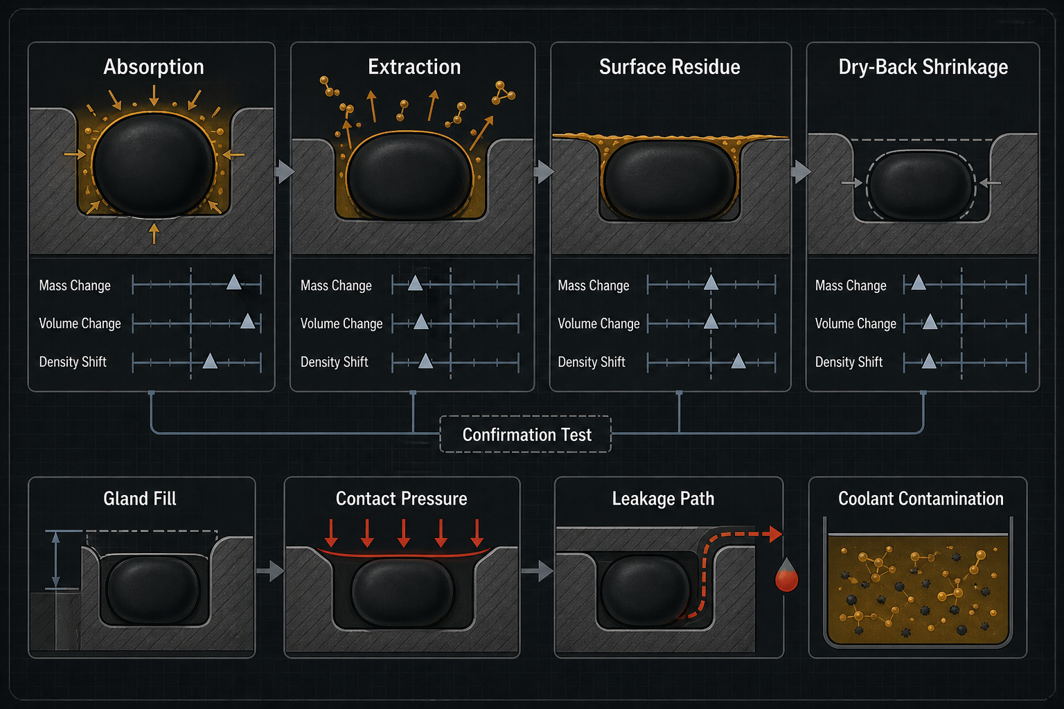
The engineering risk is misinterpretation. Mass gain can come from absorbed coolant, trapped surface film or residue. Mass loss can come from extraction, volatile loss or drying history. Volume growth can raise gland fill and extrusion risk, while dry-back shrinkage can reduce squeeze and contact pressure. The correct question is not whether the specimen changed, but whether the changed finished seal still controls leakage, air ingress, friction and coolant cleanliness. This distinction is especially severe in immersion cooling because seals may remain wetted for long periods, then be exposed to air only during service, inspection or component replacement.
Absorption, Extraction and Apparent Mass Shift in Dielectric Fluids
Dielectric fluids create several overlapping mass-transfer paths. Coolant molecules may diffuse into polymer free volume and increase wet mass. At the same time, plasticizers, process aids, oligomers or unreacted low-molecular-weight ingredients may be extracted from the seal. The two processes can offset each other, producing a small net mass change while the compound chemistry, modulus and recovery have already shifted.
A third path is apparent mass shift. Dielectric liquid can remain as a thin film in grooves, mold parting lines, rough surfaces or textile reinforcement. Cleaning residue or evaporative loss can also distort the result. These effects are not bulk absorption, yet they may be counted by a balance if the drainage and weighing procedure is weak. This is why wet mass, drained mass, dry-back mass and blank-fluid checks must be treated as separate evidence streams.
Material response depends on polymer polarity, solubility compatibility, crosslink density, filler structure, seal thickness and temperature. EPDM, FKM/FPM, silicone, HNBR, NBR, polyurethane and PTFE-based designs do not share one compatibility rule. The exact coolant formulation, additive package, operating temperature, exposure time, pressure, seal geometry and surface condition decide the outcome. Generic coolant family names are not qualification evidence. The same label can hide different base fluids, stabilizers, inhibitors, trace polar species and residue behavior.
Mass-Volume-Density Coupling in Immersed Seal Materials
Mass, volume and density form a diagnostic triangle. Mass gain with volume growth suggests fluid uptake and swelling. Mass gain without visible growth may indicate free-volume filling, surface retention or counteracting extraction. Mass loss with shrinkage may indicate additive extraction or dry-back contraction. Mass loss with retained geometry may show that compositional change has occurred before the seal shape has followed.
Density is useful because it exposes contradictions. If mass rises faster than volume, the absorbed phase or residue may be dense relative to the polymer. If volume rises faster than mass, the seal may be swelling with lower-density fluid uptake or structural relaxation. Neither case should be reduced to a simple pass or fail without dimensional mapping. A molded seal can expand at a lip, corner or constrained groove edge while its average diameter looks stable.
For finished seals, the critical dimensions are functional, not convenient. O-ring cross-section, face-seal thickness, molded lip height, valve-seat imprint, groove-fill direction and quick-disconnect sliding surfaces matter more than a single outer diameter. A plaque may show a clean percentage change while the molded part distorts anisotropically.
Table 1 – Interpreting Mass and Volume Change Patterns
| Observed Pattern | Likely Interpretation | Seal-Relevant Meaning | Misread Risk | Required Confirmation |
| Wet mass gain plus swelling | Coolant absorption | Higher gland fill and squeeze | Calling it harmless uptake | Volume, hardness, leakage |
| Wet mass gain, stable size | Free-volume uptake or residue | Hidden property drift possible | Ignoring surface film | Dry-back and drainage check |
| Dry-back mass loss and shrinkage | Extraction or desorption | Lower compression after service | Approving wet-state only | Dry dimensions and set test |
| Mass loss, geometry retained | Compositional depletion | Delayed recovery change | Missing modulus drift | Hardness and rebound |
| Local lip growth | Constrained swelling | Valve drag or seal rolling | Bulk average hides risk | Section inspection |
| Apparent gain from film | Surface retention | False compatibility trend | Mistaking residue for uptake | Blank and wipe protocol |
Compression Drift, Gland Fill and Contact-Pressure Redistribution
Volume change becomes dangerous when it changes the geometry of compression. Swelling can overfill a gland, reduce extrusion clearance and raise insertion force. In a static flange this may appear as high assembly load; in a valve, pump interface or quick-disconnect, it can become delayed movement, sticking or seal rolling. More compression is not automatically better when the material has softened or the clearance has narrowed.
Shrinkage creates the opposite problem. A seal that loses volume after extraction or dry-back may no longer generate the intended contact pressure. The leakage path may appear after maintenance, cool-down or restart rather than during the original wet pressure hold. This is common when the test captures only the immersed state and ignores what happens when the part is removed, wiped, stored and reinstalled.
Contact pressure also redistributes locally. Swelling at one lip can lift another region from the seat. A residue deposit can act as a false high spot. A softened edge can extrude into a gap and relieve compression elsewhere. Finished-seal evaluation must therefore connect dimensional drift to actual gland fill, compression map, movement and leakage evidence. It should also identify whether the critical state is the fully wet state, the partially drained maintenance state or the dry-back state before reassembly, because each can create a different contact-pressure condition.
Wet-State, Dry-Back and Surface-Residue Measurement Error
Measurement error is not a minor laboratory detail; it can decide the wrong material. A specimen taken from dielectric fluid carries surface liquid. If that liquid is not removed consistently, the result becomes a drainage test rather than a material test. If the seal is over-wiped, softened surface layers may be damaged or absorbed fluid may begin to desorb before weighing.
Dry-back behavior deserves its own record. The seal immediately after removal, the seal after controlled drainage, and the seal after defined drying are different states. A material may swell during immersion, then shrink below its original dimension after extracted ingredients and absorbed fluid leave. That sequence can be more severe for service reliability than the maximum wet swelling value.
A strong protocol records specimen ID, material lot, cure state, geometry, coolant batch, temperature, exposure time, drainage method, time to weighing, wet dimensions, dry-back dimensions and post-exposure mechanical checks. Without those controls, a percentage mass change looks precise but cannot be trusted as a mechanism statement.
Table 2 – Immersion-Test Variables That Control Data Quality
| Test Variable | Why It Matters | Common Error | Control Method | Limitation |
| Drainage method | Controls wet mass | Counting surface liquid | Defined blot or drip time | May disturb soft surfaces |
| Dry-back interval | Shows desorption | Mixing wet and dry data | Separate time points | Not always service-like |
| Finished geometry | Controls local strain | Plaque-only decision | Test molded seals | More scatter |
| Coolant batch | Defines chemistry | Generic fluid name | Record formulation/additives | Supplier changes matter |
| Temperature history | Changes diffusion | Room-only screening | Controlled exposure profile | Gradients may remain |
| Measurement feature | Defines function | Convenient dimension only | Measure sealing surfaces | Needs fixtures |
| Blank-fluid control | Finds residue loss | Assuming clean fluid | Track fluid mass/residue | May not identify source |
Dimensional Instability, Leakage Paths and Fluid Contamination
Dimensional instability does not have to create immediate visible leakage to be serious. A swollen seal may pass a pressure test while accumulating compression set. A shrunken seal may hold while the system is warm but admit air during cool-down. A softened seal may stay tight in a static fixture yet extrude under vibration or valve motion. These are seal-system failures, not just material observations.
Dielectric-fluid cleanliness adds another consequence. Extracted ingredients, wear particles from a tacky surface and residue from incompatible cleaners can enter the immersion bath. In electronic immersion systems, fluid cleanliness and material stability are part of reliability. A seal that does not leak externally can still contaminate the coolant or change local friction at a service interface.
The failure evidence should separate measured facts from suspected mechanisms. A wet trace, pressure-decay drift, air-ingress event, polished sliding band, flattened cross-section, swollen lip, brittle crack or residue ring does not mean the same thing. Each observation must be matched to immersion history, dry-back state, mechanical property drift and the geometry of the actual gland. Without that separation, a team may replace the wrong material, change the wrong coolant, or tighten a gland that is already overfilled in the wet state.
Table 3 – Material Change and Sealing Consequence
| Material or Dimensional Change | Seal-Level Effect | Observable Symptom | Recommended Verification | Engineering Response |
| Bulk swelling | High gland fill | High insertion force | Volume and leak test | Increase clearance or change compound |
| Dry-back shrinkage | Low squeeze | Leak after service | Dry dimensions and pressure decay | Revise gland or replacement rule |
| Surface softening | Low extrusion resistance | Rolled or smeared edge | Hardness and section review | Add support or screen material |
| Hardening | Poor conformity | Intermittent sealing | Hardness and roughness check | Review temperature envelope |
| Residue deposit | False high spot | Local wet ring | Blank and cleaning audit | Change cleaning/drainage |
| Extraction debris | Fluid contamination | Particles or haze | Fluid analysis | Screen compound and coolant |
| Compression-set growth | Incomplete recovery | Leak after cycling | Set and rebound test | Adjust squeeze or material |
Finished-Seal Qualification Beyond Compound Plaque Screening
Plaques are useful for material comparison, but they cannot qualify a finished immersion-cooling seal by themselves. Finished parts contain molding stresses, parting lines, flash history, surface texture, cross-section variation and functional geometry. A molded valve seal, O-ring, gasket or quick-disconnect seal may respond differently from a flat plaque made from the same compound.
Qualification should expose finished seals to the actual dielectric fluid formulation and relevant service states: continuous immersion, warm operation, cool-down, maintenance removal, controlled dry-back and reassembly. Material candidates should be compared under identical conditions, and alert levels should be tied to the gland design rather than copied from another program.
The final approval package should include raw mass data, wet and dry-back dimensions, specimen photographs, hardness or modulus checks, compression-set evidence, leakage or pressure-decay results, air-ingress checks where relevant, and a statement of untested conditions. It should explicitly say whether the data represent continuous immersion, maintenance exposure, dried reassembly or post-cycling behavior. Procurement and quality teams should not accept a material substitution or coolant change unless the data links the fluid exposure to the actual sealing interface. The qualification file should make clear which evidence is laboratory observation, which interpretation is a likely mechanism, and which remaining risk still requires system-level confirmation.
FMEA: Failure Risks from Misread Mass and Volume Change
The FMEA focuses on misread evidence, not only material degradation. Qualitative risk depends on the application, gland design, coolant, temperature, maintenance practice and validation history. The table therefore avoids numerical RPN values and treats each item as a mechanism requiring confirmation.
Table 4 – FMEA for Dielectric-Coolant Exposure of Immersion-Cooling Seals
| Failure Mode | Cause | Local Effect | System Effect | Detection Method | Control Action |
| Swelling read as harmless | Coolant absorption | Gland overfill | Extrusion or sticking | Volume and movement test | Recheck gland fill |
| Shrinkage after dry-back | Extraction/desorption | Low squeeze | Leak after service | Dry-back dimensions | Define replacement rule |
| Residue counted as mass gain | Surface film | False trend | Wrong material approval | Blank and wipe check | Control drainage |
| Incomplete drying record | Protocol gap | Unstable data | Bad comparison | Timed repeat weighing | Separate wet/dry states |
| Local swelling hidden | Constrained geometry | Lip distortion | Valve drag or leakage | Section inspection | Test finished seals |
| Short soak approval | Slow diffusion | Late drift | Long-term incompatibility | Staged exposure | Extend profile |
| Plaque data overused | Geometry mismatch | Wrong inference | Unverified gland fit | Finished-part test | Link to seal geometry |
| Exposed seal reused | Maintenance judgment | Set or residue remains | Reconnection leak | Post-service test | Set reuse criteria |
| Extracted compounds ignored | Additive loss | Fluid contamination | Cleanliness risk | Fluid analysis | Screen compound/coolant |
Conclusion
Dielectric-coolant compatibility cannot be decided by mass change alone. Immersion-cooling seals must be judged through the coupling of wet mass, dry-back mass, volume, density, local dimensions, hardness, modulus, compression set, contact pressure, leakage evidence, contamination risk and service history. The most dangerous error is not a wrong percentage; it is a correct measurement attached to the wrong mechanism. Reliable qualification separates measured evidence, possible mechanism, engineering hypothesis and confirmation test, then verifies the finished seal in the real dielectric fluid and the real gland.
FAQ
Q:Does mass gain prove that a seal has swollen?
A:No. Mass gain may come from absorbed coolant, retained surface film, filler wetting or incomplete drainage. Swelling must be confirmed by volume or dimensional measurements at functional seal features. A seal can gain mass with little visible growth and still suffer hardness, modulus or compression-set drift. Treat mass gain as a diagnostic signal, not as proof of bulk expansion.
Q:Why can a seal gain mass without obvious dimensional growth?
A:Fluid may occupy polymer free volume or surface roughness before external dimensions change. Extraction can also offset absorption, leaving net geometry stable while composition changes. Filled or molded seals may hide local swelling in one lip or corner. Confirmation requires dry-back comparison, section inspection, density interpretation and mechanical-property checks, not a single wet mass value.
Q:How should wet surface liquid be removed before weighing?
A:Use a defined drainage or blotting method and record the time between removal and weighing. The process should remove free liquid without extracting absorbed coolant or damaging a softened surface. Apply the same method to all specimens, controls and intervals. If the method changes, the apparent mass trend may reflect handling rather than material response.
Q:Can dielectric coolant extraction cause seal shrinkage?
A:Yes. If plasticizers, process aids or other low-molecular-weight ingredients leave the compound, the seal may lose mass and shrink, especially after drying or repeated immersion and desorption. Shrinkage can reduce contact pressure even if the wet seal looked acceptable. Confirm the mechanism with dry-back dimensions, hardness, rebound and compression-set evidence.
Q:Which is more important: mass change, volume change, or leakage data?
A:None is sufficient alone. Mass change identifies material-fluid interaction, volume change shows fit and compression risk, and leakage data proves system-level behavior. The decision should connect those three with gland fill, extrusion clearance, compression set, dry-back state and functional testing. A low mass change can still be unacceptable if the seal loses recovery or contaminates the fluid.
Q:Can a short immersion test prove long-term compatibility?
A:No. A short soak can reject obviously incompatible materials, but slow diffusion, extraction, desorption, compression-set growth and dry-back shrinkage may appear later. Thermal cycling, vibration, maintenance removal and restart can expose failure modes that a simple immersion coupon misses. Long-term claims require a representative exposure profile and finished-seal validation.
Q:Should an exposed immersion-cooling seal be reused after maintenance?
A:Reuse should not be based on appearance alone. An exposed seal may contain absorbed coolant, extracted compound ingredients, surface residue, compression set or changed friction while still looking intact. Reuse decisions should consider exposure history, wet and dry-back dimensions, surface condition, hardness or rebound where relevant, and post-assembly leakage or pressure-decay testing.
Post time: Sep-09-2026