
Executive Summary
A liquid-cooling quick-disconnect uses its locking mechanism for more than separation prevention. The latch, sleeve, balls, collet, clip or threaded ring controls the final axial position of the coupling halves. That position determines whether O-rings, face seals, poppet seals and valve seats reach their intended compression. A connection can therefore appear closed while a sealing interface remains under-compressed, skewed or locally overloaded.
Incomplete engagement, rebound, wear, tolerance stack-up, debris and thermal movement can create seepage, air ingress, pressure-decay drift, delayed valve closure or flow restriction. Excessive locking load can damage a seal just as insufficient locking can reduce contact pressure. Static holding, lock-force measurement and visual indication answer different questions. The interface must be evaluated as a coupled locking-position and seal-compression system.
Quick-Disconnect Architecture and Sealing Boundaries
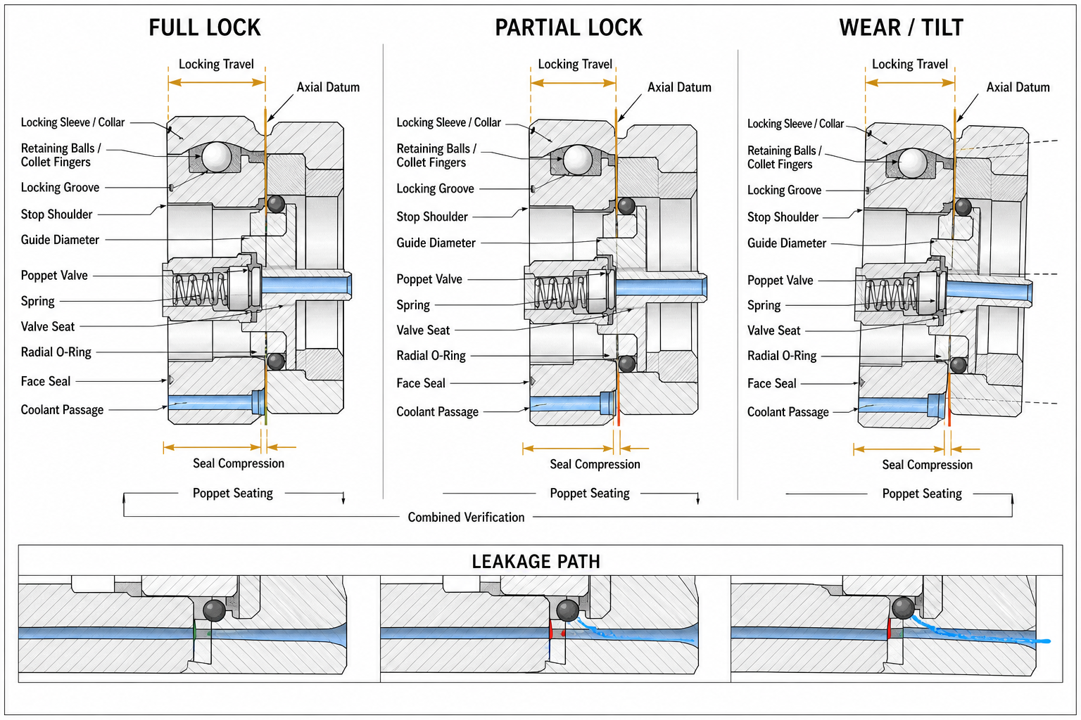
A server liquid-cooling quick-disconnect may sit between a CDU, cold plate, manifold, hose assembly or service panel. The assembly commonly includes male and female coupling bodies, a locking sleeve or collar, a ball-lock or collet mechanism, a retaining clip, a secondary lock, a visual indicator, poppets, valve springs, guide surfaces, stop shoulders and one or more O-rings or face seals. Each element has a different role in the load path. The locking parts retain and position the coupling; the seals block coolant or gas migration; the poppets control flow when the coupling is separated.
The external coupling-body seal, internal valve-seat seal, hose-to-coupling seal and service-interface seal should be treated as separate pressure boundaries. A radial O-ring depends on gland compression and surface contact around a circumference. A face seal depends on axial seating and parallel surfaces. A poppet seal depends on spring force, stem alignment, seat condition and pressure assistance. The stop shoulder, guide diameter and locking travel determine whether these interfaces reach their intended positions.
Table I — Quick-Disconnect Locking and Sealing Boundaries
| Boundary or component | Primary function | Load or exposure | Seal-compression relevance | Typical risk | Verification focus |
| Locking sleeve / collar | Axial retention and positioning | Manual force, vibration, wear | Controls final coupling position | Partial lock or rebound | Travel and position check |
| Ball, collet or retaining clip | Mechanical capture | Separation load, fretting | Maintains seal preload indirectly | Wear or deformation | Engagement and retention test |
| Stop shoulder and guide | Alignment and axial datum | Assembly force, thermal movement | Sets seal and poppet location | Gap, tilt or eccentricity | Axial and concentricity measurement |
| Poppet and valve seat | Flow shutoff | Pressure, spring force, particles | Requires repeatable seating | Delayed closure or seepage | Opening, closing and leakage test |
| O-ring or face seal | Fluid barrier | Coolant, temperature, movement | Directly carries compression | Low compression, extrusion or cut | Seal inspection and pressure test |
| Hose-to-coupling interface | Hose retention and sealing | Pull, bending, pressure thrust | Can load the coupling unevenly | Hose slip or interface leak | Routing and pull-off verification |
Locking Mechanism, Axial Positioning and Load Transfer
During connection, the halves pass through insertion, poppet opening, stop contact and locking engagement. A sleeve may drive balls into a groove, a collet may engage a shoulder, a clip may capture a flange, or a threaded ring may draw the halves together. The mechanism transfers separation load into the body, while its travel defines the axial position at which the seals are compressed. If the stop is not reached, the latch may move while the coupling remains short of its sealing datum.
Partial engagement is difficult to identify when a sleeve rebounds, a ball is contaminated, a secondary lock is omitted or an indicator is insensitive to internal position. Manufacturing tolerances, hose tension, pressure thrust, vibration and thermal movement can compound axial, radial and angular misalignment. Thread wear or an obstructed shoulder may prevent face contact even when a ring appears fully rotated.
Locking force is therefore incomplete as a control variable. Evaluation should include locking travel, final position, preload, contact-pressure distribution, alignment, spring force, pressure, hose load, temperature, wear, debris and reconnection history.
Table II — Locking Conditions and Seal-Compression Risks
| Locking condition | Primary positional effect | Seal-compression effect | Potential failure mode | Required control | Main limitation |
| Full engagement | Stable axial datum | Design compression may be reached | Hidden damage can remain | Position plus leakage check | Indicator alone is insufficient |
| Partial engagement | Short or unstable axial position | Local low compression | Seepage or air ingress | Positive lock verification | May look connected |
| Lock-sleeve rebound | Incomplete retention | Compression varies during vibration | Micro-motion and wear | Rebound and retention test | Depends on coupling design |
| Axial or radial misalignment | Uneven load path | Circumferential pressure imbalance | Seal roll, cut or extrusion | Alignment control | Static checks may miss it |
| Locking-groove or clip wear | Increased axial clearance | Preload decays in service | Separation or pressure-decay drift | Durability and dimensional check | Wear rate is design-specific |
| Debris interference | Blocked travel or tilted datum | Local over- or under-compression | Persistent seepage | Cleanliness and inspection | Residue may be hidden |
| Thermal movement | Relative position changes | Compression shifts with temperature | Cool-down air ingress | Thermal cycling with pressure | Material and geometry dependent |
How Locking Conditions Change Seal Compression
A radial O-ring requires squeeze and a controlled gland gap; a face seal requires axial compression and parallel surfaces; a poppet seal requires repeatable contact with its seat. Locking travel determines whether these conditions are reached together. Incomplete travel can leave an O-ring near the gland edge, a face seal with a discontinuous contact band, or a poppet that opens but does not fully reseat.
Misalignment redistributes contact pressure. A lock sleeve, ball or collet can load one side and tilt the coupling, while a loose mechanism permits axial oscillation under vibration or hose reaction. The result may be fretting, rolling, twist marks, extrusion, pinch marks and debris. Particles in a groove or guide can create a small high spot that prevents uniform compression.
Over-compression is not a universal solution. It can raise insertion force, damage a seal edge, increase friction, accelerate compression set and reduce recovery after maintenance. Under-compression can form a microchannel when pressure, temperature or coupling position changes. A normal locking sound or indicator does not confirm contact pressure; evidence must connect position, seal condition, pressure behavior and valve response.
Tolerance, Wear, Temperature, Coolant and Contamination Interaction
The final seal state is governed by tolerance stack-up across the body, stop, groove, sleeve, balls, collet, clip, guide and gland. Wear can increase clearance or allow tilt without an obvious defect. Fretting, corrosion, thread damage, clip deformation and scoring may change the load path after service, so an initially acceptable coupling may develop a different compression state after reconnection.
Coolant chemistry and temperature modify seal material and locking friction. Water-glycol and dielectric coolants may cause swelling, shrinkage, softening, hardening, tackiness or stress relaxation depending on the compound. Thermal expansion changes metal, polymer and spring positions. Low-temperature connection can raise insertion force, while elevated operation can reduce stiffness. Compatibility and a room-temperature lock check do not prove stability across the service range.
Particles, machining residue, cleaners and incorrect lubricants can obstruct a groove, alter friction or bridge a seal. Distinguish coolant residue from condensation and cleaning residue. Preserve the coupling, locking parts, poppets, seals, coolant and service history instead of inferring cause from one wet mark.
Seal Geometry, Locking Mechanism and Coupling Design Selection
O-rings, quad-rings, face seals, profiled seals, molded seals, bonded seals, backup-supported seals and poppet seals respond differently to movement. EPDM, FKM, FVMQ, NBR, HNBR, silicone, FFKM and PTFE-encapsulated designs should be compared for coolant compatibility, compression set, friction stability, extrusion, thermal cycling, particles and reconnection. The choice depends on coolant, geometry, temperature, pressure and service method.
The lock must be designed with the gland, stop, guides and valve spring. Excessive clearance permits seal micro-motion; excessive rigidity can convert misalignment into local over-compression. Ball-lock, collet-lock, sleeve-lock, threaded-lock and clip systems have different wear signatures. A visual indicator improves usability but cannot replace dimensional, retention and leakage verification. The objective is a repeatable relationship between lock position, contact pressure, valve response, flow resistance and service effort.
Inspection, Testing and Failure-Analysis Logic
Inspection should cover the indicator, sleeve, secondary lock, coupling ends, poppets, seats, groove, balls, collet, clip and threads. Dimensional checks can record axial position, travel, concentricity, angular alignment, seal section and gland depth. Magnified inspection may reveal roll marks, cuts, extrusion, pinch marks, seat imprint, debris or fretting that a visual check cannot show.
Static liquid or gas holding, pressure decay, liquid leakage, air ingress and helium leakage address different paths. Locking-force measurements assess mechanism behavior, not contact pressure. Repeated connection cycling reveals wear. Combined pressure-and-locking, vibration, thermal, valve-opening and valve-closing tests expose interactions. Define coupling type, seal geometry, coolant, pressure, temperature, alignment, history and method.
Use evidence labels—Observed, Suspected, Confirmed, Inconclusive and Not evaluated. Record lock state, position, temperature, pressure, flow, leakage, valve response and movement. Preserve unused and failed comparisons. A normal indicator, maximum lock force or passing static hold is not proof of long-term integrity.
Table III — Quick-Disconnect Locking and Seal Verification Guide
| Test or inspection | Test objective | Key variable | Detectable issue | Suitable stage | Main limitation |
| Visual lock verification | Confirm user-visible engagement | Indicator and sleeve position | Partial or false lock | Assembly and service | May miss internal gap |
| Axial-position measurement | Confirm sealing datum | Final position and travel | Stop or tolerance error | Design and audit | Needs defined datum |
| Seal inspection | Find physical damage | Cross-section, marks, debris | Cut, roll, extrusion | Failure analysis | Cannot prove dynamic behavior |
| Static pressure holding | Check steady barrier | Pressure, time, temperature | Gross leakage | Screening | Not a cycle test |
| Air-ingress or helium test | Find gas pathways | Vacuum or gas condition | Microchannels and ingress | Validation and FA | Not equal to coolant migration |
| Locking-force measurement | Characterize mechanism | Engagement and release force | Wear, obstruction, friction shift | Design and maintenance | Not seal contact pressure |
| Repeated connection cycling | Assess reconnection durability | Cycle history and position | Wear and seal damage | Qualification | Profile must be defined |
| Combined pressure and locking test | Link lock state to leakage | Pressure, position, leakage | Leak-before-separation | Validation | Coupling-specific |
| Thermal and vibration testing | Expose movement interactions | Temperature, vibration, pressure | Micro-motion and drift | Qualification | Needs representative routing |
| Valve response testing | Confirm poppet function | Opening, closure, flow | Delayed closure or restriction | Validation and service | Does not cover every seal path |
| Post-maintenance verification | Confirm restored integrity | Lock, leak, air ingress | Assembly or cleaning error | Every service event | Must match service procedure |
Assembly, Maintenance and Long-Term Reliability
Before connection, align the halves and remove particles from the seal, guide and locking surfaces. Do not use the lock to compensate for hose strain, angular misalignment or an obstructed stop. Confirm insertion, sleeve travel, visual indication and secondary-lock engagement separately. Control lubricant type and amount because it can change friction, retain debris or affect the coolant.
After maintenance, verify retention, liquid leakage, pressure decay, air ingress, valve opening and valve closure. Seal and locking-component reuse require separate criteria; an intact-looking seal may have compression set, while a functioning latch may be worn. Trace coupling, seal, hardware, coolant, service event and test result. Any change in dimensions, latch, gland, poppet, coolant or service procedure requires renewed locking–compression validation.
FMEA Risk Analysis: Liquid-Cooling Quick-Disconnect Locking Mechanisms and Seal Compression
The locking mechanism establishes the axial position of the coupling halves and transfers separation load into the body. Partial engagement, wear, misalignment, tolerance stack-up and debris can change seal compression even when the visible indicator appears normal. A seal may then experience low compression, over-compression, extrusion, rolling, cutting, wear or compression set. Poppets, valve seats and external seals must be assessed together because flow and sealing functions interact. Static holding, lock-force measurement and visual checks are separate evidence streams. The RPN values below are illustrative engineering risk rankings, not field statistics or experimental results.
Table IV — FMEA Risk Analysis
| Failure mode | Cause | Local effect | System effect | Detection method | RPN | Corrective action |
| Incomplete or partial locking; sleeve rebound | Short travel, obstruction, user error | Axial gap; unstable preload | Coolant seepage or separation | Lock position, retention and leak test | Illustrative—High | Positive lock feature; cleaning; functional check |
| Locking-groove, ball, collet or clip wear | Repeated service, fretting, corrosion | Clearance and tilt increase | Pressure-decay drift or release | Dimensional and durability check | Illustrative—High | Wear limit; replace hardware; trace cycles |
| False lock indication; secondary lock omitted | Indicator tolerance or procedure error | Internal position unconfirmed | Latent leakage risk | Independent position and leak check | Illustrative—High | Redundant indication and training |
| Axial, radial or angular misalignment | Routing load, tolerance, damaged guide | Uneven seal contact | Local leak, flow restriction | Alignment and contact inspection | Illustrative—High | Guide redesign; strain relief; alignment control |
| Local low or excessive compression | Stop error, tolerance stack-up, lock overtravel | Microchannel or seal damage | Leakage, air ingress, difficult service | Position, seal and pressure analysis | Illustrative—High | Control datum; optimize gland and stop |
| Seal extrusion, rolling, twisting, pinching or cutting | Edge damage, friction, skew, poor lubrication | Seal section displaced or scored | Coolant leakage and debris | Magnified inspection; failure analysis | Illustrative—High | Chamfer, lubrication and assembly controls |
| Poppet misalignment or delayed closure | Guide wear, spring change, particles | Seat contact unstable | Flow restriction or carryover leak | Opening/closure and flow test | Illustrative—Medium | Guide, spring and cleanliness control |
| Coolant-induced swelling or shrinkage; thermal damage | Incompatible compound or temperature cycling | Friction and compression change | Reconnection leakage or air ingress | Immersion, thermal and dimensional test | Illustrative—Medium | Material screening and envelope validation |
| Vibration micro-motion; fretting; particles | Loose mechanism, routing load, contamination | Wear debris and seal polish | Progressive leak or lock degradation | Vibration, debris and position record | Illustrative—High | Retention stiffness; particle control; routing support |
| Thread under-engagement or stop damage | Wear, cross-threading, obstruction | Face contact incomplete | Seal under-compression | Thread and stop inspection | Illustrative—High | Lead-in control; torque or position verification |
| Repeated reconnection damage or seal reuse | Improper service, hidden set | Seal recovery reduced | Post-maintenance leakage | Service record and comparison seal | Illustrative—Medium | Replacement criteria and procedure control |
| Inadequate locking–compression validation | Isolated static or visual testing | Interaction not measured | Latent field failure | Combined pressure, motion and cycling test | Illustrative—High | Representative qualification plan |
Conclusion
A liquid-cooling quick-disconnect latch is part of the sealing system because it controls axial position, preload and valve alignment. Partial engagement, wear, tolerance stack-up, misalignment, particles, vibration and thermal movement can change seal compression before a coupling visibly separates. Locking force, locking travel, final position, contact pressure, poppet response and leakage must be evaluated together. A normal indicator, a passing static pressure hold or a measured lock force cannot substitute for repeated connection, pressure, temperature, vibration and post-maintenance validation. Long-term reliability comes from coordinated coupling geometry, locking hardware, seal design, coolant control, assembly discipline and evidence-based testing.
FAQ
Q:How can a quick-disconnect locking mechanism affect seal compression?
A:The mechanism sets final axial position. Incomplete, worn or obstructed travel can leave an O-ring, face seal or poppet under-compressed; excessive travel can cause over-compression. The indicator shows a visible state, not necessarily contact pressure. Evaluate position, seal condition and leakage together.
Q:Can a coupling appear locked while the seal is still under-compressed?
A:Yes. A sleeve or ball may move normally while tolerance, debris, thread damage or misalignment keeps the coupling short of its shoulder. The result may be seepage, pressure-decay drift or air ingress during cool-down. Position measurement or a combined pressure-and-locking test is more informative than appearance.
Q:Why is axial positioning important for liquid-cooling quick-disconnect seals?
A:Position determines whether a face seal is seated, an O-ring remains in its gland and a poppet reaches closing contact. It can also change spring compression and opening force. Evaluate position with radial and angular alignment because average position can hide uneven contact. Static holding does not reveal every weakness.
Q:How can locking wear increase coolant leakage risk?
A:Wear at a groove, ball, collet, clip, sleeve or thread increases clearance and permits movement. Micro-motion can polish, roll or abrade the seal and generate debris. Early evidence may be pressure-decay drift or a wetting trace. Define wear limits and repeated-connection checks for the coupling.
Q:Can excessive locking force damage a quick-disconnect seal?
A:Yes. Excessive force may indicate over-travel, poor alignment, incompatible lubrication, guide damage or an obstructed shoulder. Local compression can cut an O-ring, deform a face seal or accelerate compression set. Low release force is not automatically safer because retention may be insufficient. Interpret force with final position.
Q:Which tests are useful for confirming lock-related seal failure?
A:Useful evidence includes lock-travel and position measurement, seal inspection, static holding, pressure decay, air-ingress or helium testing, lock-force measurement, repeated connection cycling and combined pressure-and-locking tests. Thermal and vibration testing can expose micro-motion. Gas tests do not automatically predict coolant migration, and lock-force data do not prove contact pressure.
Q:How should a quick-disconnect coupling be inspected after reconnection or maintenance?
A:Confirm cleanliness, seal condition, poppet movement, alignment, insertion, sleeve travel, indication and secondary-lock engagement separately. Then verify leakage, pressure decay, air ingress and valve response. Do not reuse a seal or locking component solely because it looks intact. Record the coupling, seal, coolant, service event and test result.
Post time: Sep-09-2026