
Executive Summary
Immersion-cooling tank-lid sealing must keep dielectric liquid inside the tank while also controlling the vapor space and long-term gas-tightness boundary. Prolonged fluid exposure can cause absorption, extraction, swelling, shrinkage, softening, hardening, tackiness and compression-force drift. These changes matter only after they are connected to actual lid geometry, gasket compression, flange flatness, fastener load and maintenance history.
A tank may pass a short liquid-hold check while still allowing vapor or gas migration through a low-pressure interface. Static immersion data also cannot represent thermal cycling, liquid-level movement, vapor condensation, repeated opening or reassembly damage. Evaluation must consider liquid leakage, gas migration, coolant contamination, insulation risk and post-maintenance resealing. Immersion-tank lid sealing should be evaluated as a coupled liquid-containment and gas-tightness system rather than as a material-compatibility problem alone.
Immersion-Tank Sealing Architecture and Functional Boundaries
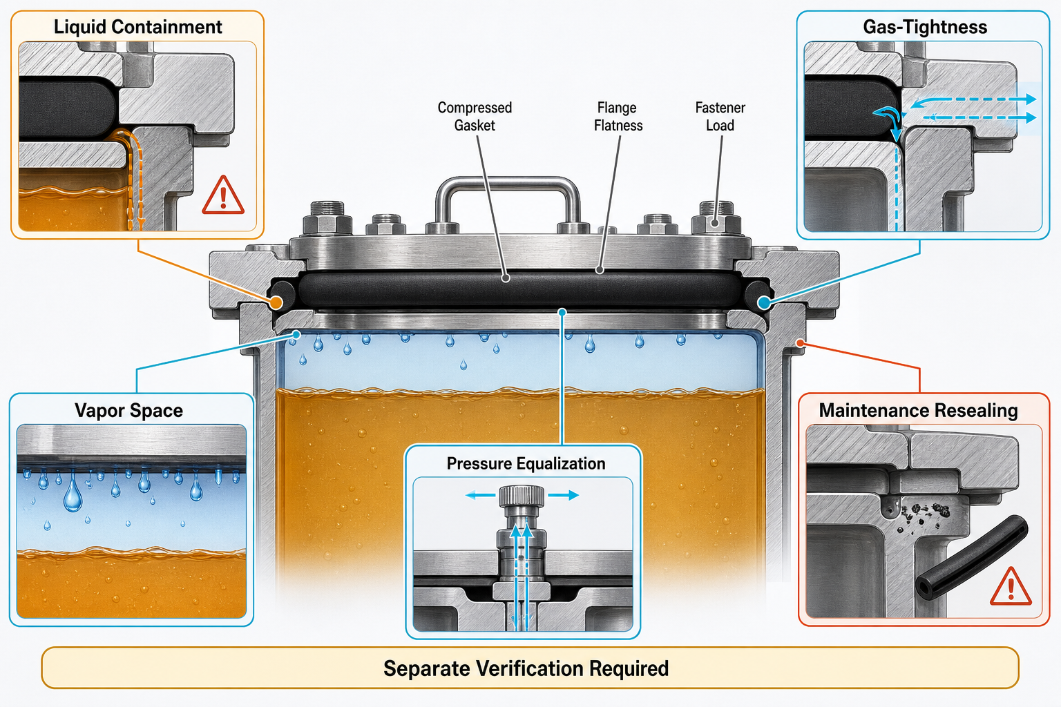
The sealing architecture includes the tank body, removable lid, perimeter flange, gasket groove, flat or profiled gasket, O-ring or cord seal, fasteners, clamps, hinges, cable and pipe penetrations, drain and fill ports, pressure-equalization feature, vapor space, liquid level, support frame and cooling-loop interface. These parts do not perform one identical sealing duty. The lower region may face continuous liquid wetting and possible wicking, while the upper region may face vapor, condensate, pressure breathing and external air.
Flange flatness, lid stiffness, fastener spacing, preload distribution and assembly sequence decide whether circumferential compression is continuous. Cable, pipe and sensor penetrations can become independent leakage paths because they add bending loads and service interfaces. A pressure-equalization feature manages pressure change; it is not a replacement for the perimeter lid seal. Liquid containment, gas barrier, pressure equalization and maintenance resealing must therefore be defined and verified separately.
Table I: Immersion-Tank Sealing Boundaries and Functions
| Boundary | Function | Exposure | Risk | Verification | Limitation |
| Liquid-side gasket | Block coolant | Liquid wetting | Seepage | Liquid hold | Not gas proof |
| Vapor-space gasket | Limit gas exchange | Vapor, condensate | Permeation | Tracer gas | Not liquid soak |
| Lid flange | Carry compression | Load, warpage | Local gap | Flatness map | Needs stiffness |
| Cable penetration | Seal entry | Bend, residue | Local leak | Local test | Independent path |
| Drain or fill joint | Service fluid | Coolant handling | Joint leak | Inspection | Maintenance driven |
| Pressure feature | Equalize pressure | Vapor pressure | Bypass or block | Function test | Not lid seal |
Dielectric-Fluid Exposure and Seal-Material Response
Dielectric immersion fluids may be mineral-based, synthetic hydrocarbon, ester-based or silicone-based, and each may contain additives, oxidation products or moisture. Single-phase systems mainly expose seals to liquid and vapor, while two-phase systems increase vapor and condensation effects. Compatibility cannot be judged from the fluid name alone; compound formulation, temperature, exposure duration, liquid level, vapor condition, pressure state and seal geometry all affect response.
Fluid molecules can enter the rubber network, changing mass, volume, hardness and viscoelastic behavior. Absorption may increase section size and groove fill, but it can also distort corners, increase extrusion risk or redistribute contact pressure. Extraction of mobile constituents can cause shrinkage, hardening, embrittlement or reduced recovery. Softening raises creep and local instability risk; hardening reduces the ability to compensate flange gaps.
Liquid immersion and vapor exposure can produce different evidence. Submerged zones may show bulk swelling or softening, while vapor-space zones may show surface tackiness, condensate staining or permeability change. Over time, these responses can reduce sealing force, create debris, increase gas permeability or open leakage paths. Material exposure results are therefore evidence of response, not direct proof of long-term gas-tightness.
Table II: Dielectric-Fluid Exposure and Seal-Response Matrix
| Factor | Seal response | Secondary effect | Failure mode | Control | Limitation |
| Fluid composition | Absorption or extraction | Volume drift | Seepage path | Compound screen | Name insufficient |
| Additives | Surface change | Residue | Particle risk | Aged-fluid review | Package varies |
| Temperature | Faster aging | Stress loss | Gas path | Thermal exposure | Static data limited |
| Vapor exposure | Surface response | Permeation | Vapor migration | Vapor test | Not liquid soak |
| Moisture | Chemistry shift | Insulation concern | Ingress risk | Coolant analysis | Source uncertain |
| Thermal cycling | Relative motion | Gap opening | Boundary loss | Cycle test | Assembly dependent |
Compression, Flange Deformation and Gas-Tightness Retention
A lid gasket needs enough continuous contact pressure to maintain both liquid and gas boundaries. Low initial compression can leave micro-channels at surface waviness, gasket joints, corners or regions between fasteners. Excessive compression can appear safe at assembly but accelerate compression set, stress relaxation, extrusion or permanent deformation. The useful condition depends on compound, cross-section, groove fill, flange geometry and load path.
Flange flatness and lid stiffness are coupled with seal section. A flat gasket may cover a broad surface but lose pressure where the lid bows; an O-ring can create high local stress but may be sensitive to groove damage or twisting. Thermal expansion of lid, tank body and fasteners changes preload during start-up and cool-down. Warpage can reduce pressure at corners, center spans or fastener-between zones while adjacent areas remain over-compressed.
Liquid leakage, vapor permeation, gas leakage, external moisture ingress and coolant wicking are not the same evidence. A tank may show no visible coolant loss while allowing gas movement through a small low-pressure channel. After service, recompression cannot be treated as a new-seal condition because gasket, fasteners, flange surface and tank body may have changed.
Thermal Cycling, Fluid Motion and Operating-Condition Effects
Operation adds conditions that static storage cannot represent. Start-up heating, cool-down and repeated thermal cycling produce relative displacement between lid, flange, tank body, fasteners and seal. Vapor-space pressure changes with liquid temperature, liquid level and trapped gas volume. Pressure-equalization components must be tested as independent functions, not assumed to be harmless leakage paths through the lid gasket.
Liquid-level change alters which parts of the seal are immersed and which parts face vapor or condensate. Sloshing creates periodic wetting and local loading near the lid perimeter, especially during movement or maintenance handling. Pump fluctuation, fan vibration and structural vibration can cause micro-slip, polish contact surfaces, move residue, generate particles or pump coolant along a marginal interface.
Coolant temperature influences viscosity, wetting and leak visibility. A cold fluid may hide a path that appears after warming, while shutdown condensation may introduce moisture at a boundary that looked dry in service. Refill and drain cycles can disturb the vapor space and trap air. Lid sealing should therefore be evaluated under combined liquid, gas, temperature, vibration and maintenance cycles.
Material, Seal Geometry and Assembly-Process Selection
Potential materials include EPDM, FKM, FVMQ, NBR, HNBR, silicone, fluorosilicone, closed-cell foam and sponge materials, but no polymer family is a universal best choice. Selection should compare dielectric-fluid compatibility, mass and volume change, compression-set resistance, stress relaxation, gas permeability, vapor response, thermal-cycle stability, tackiness, particle generation, installation repeatability, reworkability, cleaning compatibility and aging. Each compound must be checked against the actual fluid and enclosure.
Geometry defines whether material capability becomes boundary performance. Molded perimeter gaskets reduce joint risk but require accurate grooves. Flat-cut gaskets cover large lids but may be sensitive to bolt spacing and waviness. O-rings and cord seals generate high unit pressure but can twist or roll. Foam seals accommodate gaps but may raise permeability or compression-set concerns. Liquid-applied sealants can fill irregularities, yet residues, cure by-products and reworkability must be controlled.
The design must match seal section, corner radius, joint method and locating feature to lid stiffness, flange flatness and fastener layout. Very soft materials may creep, extrude or take local set; very hard materials may fail to bridge small gaps after thermal distortion. The correct answer is a validated combination of compound, geometry, groove, lid, flange, fasteners and service process.
Maintenance, Reassembly and Contamination Control
Tank opening is a sealing event. Fluid draining, fluid recovery, lid removal, gasket removal, groove cleaning, flange cleaning, seal inspection and reuse decisions can change seal shape, surface condition and recovery. A used gasket may look acceptable while carrying compression set, absorbed coolant, extracted constituents or hidden surface damage. Reuse should depend on condition history and verification, not appearance alone.
Groove residue, coolant film, cleaning-agent residue, particles, fibers and metal fragments can create local standoff or micro-channels. O-rings can twist, stretch or roll; flat gaskets can be pinched or mislocated; profiled gaskets can be damaged at corners or joints. Lubricants must be compatible with both the dielectric fluid and the seal material.
Reassembly should control fastener replacement, clamp condition, torque sequence, seating sequence and alignment. After refilling, air removal and vapor-space restoration, the system should be verified separately for liquid containment and gas-tightness. Maintenance records should link seal batch, coolant batch, opening count, cleaning method, fastener action and test result.
Verification, Failure Analysis and Process Control
Verification must separate material response from boundary function. Visual inspection, dimensional inspection, gasket cross-section measurement, mass and volume change, hardness measurement, compression-set testing and stress-relaxation testing describe seal change. Immersion exposure, vapor exposure and thermal cycling define the environment. Pressure-decay testing, helium leak testing, tracer-gas testing, liquid-hold testing, moisture-ingress testing and pressure or vacuum cycling evaluate enclosure function under defined conditions.
Each method has limits. Mass change after immersion can indicate absorption or extraction but cannot prove long-term gas-tightness. A leak-rate test confirms boundary function at the tested state, but it does not identify whether the mechanism is swelling, flange flatness, lid warpage, particle entrapment or incorrect reassembly. Helium or tracer-gas tests can find gas paths invisible to liquid-hold testing, but they do not automatically represent coolant wicking.
Failure analysis should preserve evidence before cleaning or disassembly alters it. Useful records include coolant sample, seal sample, unused comparison seal, lid flatness data, flange condition, fastener history, compression mapping, residue inspection, coolant contamination analysis, extractables analysis and post-maintenance leak results. Evidence status should be stated as observed, suspected, confirmed, inconclusive or not evaluated.
Table III: Immersion-Tank Seal Verification Guide
| Test | Objective | Key variable | Detects | Stage | Limitation |
| Material exposure | Check compatibility | Fluid and vapor | Swelling, extraction | Design | Not enclosure proof |
| Liquid hold | Find liquid loss | Fill and orientation | Seepage | Prototype or service | May miss gas path |
| Gas test | Check gas boundary | Gas and pressure | Micro-channel | Prototype or audit | Not root cause |
| Thermal cycle | Check stability | Cycle profile | Compression drift | Validation | Needs real assembly |
| Flange and lid | Check structure | Flatness, warpage | Low-pressure zone | Build or failure | Static snapshot |
| Post-maintenance | Verify reseal | Assembly state | Service leak | After opening | Not prior cause |
| Coolant analysis | Find contamination | Residue, extractables | Material or ingress signal | Failure analysis | Source uncertain |
FMEA Risk Analysis: Immersion-Tank Lid Sealing and Gas-Tightness Retention
The FMEA connects fluid exposure, material response, compression state and enclosure function. Swelling, shrinkage, softening, hardening, compression-set growth and stress relaxation can change contact pressure and open leakage paths. Lid warpage, flange flatness deviation and fastener-load variation can create low-compression zones even when the material remains chemically stable. Liquid seepage, gas leakage, vapor permeation and moisture ingress are different effects, so material, lid, flange, fasteners, coolant, penetrations and maintenance must be evaluated together. The RPN values are illustrative engineering risk rankings, not field statistics or experimental results.
Table IV: FMEA Risk Analysis
| Failure mode | Cause | Local effect | System effect | Detection | RPN | Corrective action |
| Fluid swelling | Absorption | Distortion | Seepage or extrusion | Dimension check | 64 | Match groove and compound |
| Shrinkage | Extraction | Lower compression | Gas path | Volume check | 72 | Screen aged fluid |
| Softening | Fluid or heat | Creep | Debris or leak | Hardness check | 56 | Change compound |
| Hardening | Aging | Poor recovery | Gap leakage | Recovery test | 63 | Control replacement |
| Compression set | Long dwell | Force loss | Leak after cycling | Set test | 80 | Define limits |
| Stress relaxation | Load and heat | Pressure drift | Gas loss | Relaxation test | 70 | Improve section |
| Low compression | Gap or load error | Micro-channel | Boundary leak | Compression map | 84 | Correct flange and torque |
| Lid warpage | Thermal load | Span pressure loss | Vapor migration | Deformation check | 81 | Increase stiffness |
| Uneven preload | Torque error | Mixed pressure | Early leak | Torque audit | 76 | Controlled sequence |
| Residue or particles | Poor cleaning | Local standoff | Micro-channel | Groove inspection | 69 | Clean and verify |
| Penetration leak | Service motion | Local path | Boundary failure | Local leak test | 75 | Seal separately |
| Unverified gas assumption | Liquid test only | Hidden gas path | False reliability claim | Gas test | 88 | Separate tests |
Conclusion
Immersion-cooling tank-lid sealing is a coupled enclosure function. The gasket material must tolerate dielectric-fluid exposure, but material tolerance alone does not preserve liquid containment, vapor-space control or gas-tightness. Compression distribution, lid stiffness, flange flatness, fastener preload, vapor behavior, thermal cycling, fluid motion and maintenance practice determine whether a continuous boundary survives service. A credible program separates liquid-hold testing from gas-tightness testing, distinguishes material response from assembly leakage, and records evidence before maintenance destroys root-cause information. Long-term enclosure integrity is built through validated materials, controlled geometry, stable compression, disciplined reassembly and layered verification.
FAQ
Q:Why is liquid immersion resistance not the same as gas-tightness retention?
A:Liquid immersion resistance describes how a seal material responds to dielectric fluid. Gas-tightness retention describes whether the assembled lid boundary limits air, vapor or moisture movement. A swollen material may still leave a low-pressure channel, and a liquid-hold test may not reveal gas migration. Immersion, thermal cycling and maintenance reassembly must be verified separately because no single test proves all long-term functions.
Q:Which properties should be evaluated when selecting a seal for an immersion-cooling tank lid?
A:Selection should include mass and volume change, hardness drift, compression set, stress relaxation, gas permeability, vapor response, thermal-cycle stability, particle generation, installation repeatability and cleaning compatibility. Liquid leakage and gas leakage depend on different sensitivities. A compound that survives immersion may still relax under compression or leak after lid removal. The test plan must match the fluid, geometry and service process.
Q:How can dielectric-fluid swelling change lid-seal performance?
A:Swelling can increase groove fill and local compression, but it can also distort corners, promote extrusion, shift contact pressure and reduce installation tolerance. If swelling differs between liquid and vapor zones, the lid may develop inconsistent pressure. A liquid-hold result after swelling does not prove gas-tightness after cycling or maintenance. Dimensional checks, compression mapping and gas testing are needed.
Q:Why can flange flatness and lid stiffness affect gas leakage?
A:Gas leakage can occur through small low-pressure paths that may not pass visible liquid during a short hold test. Flange waviness, lid bowing, fastener spacing and uneven preload can reduce contact pressure between loaded points. Thermal cycling may move these zones. Flatness measurement and lid deformation checks help separate structural leakage from material incompatibility.
Q:Can a seal that passes a liquid-hold test be considered reliable for long-term immersion cooling?
A:No. A liquid-hold test verifies liquid containment only under the tested orientation, fill level and assembly state. It does not demonstrate gas-tightness, vapor control, moisture exclusion or performance after thermal cycling and reassembly. Long-term reliability requires evidence for material exposure, compression retention, flange condition, gas leakage and post-maintenance resealing.
Q:How should an immersion-tank lid seal be inspected after maintenance?
A:Inspection should include the seal surface, groove, flange, compression marks, residue, particles, fibers, metal fragments, twisting, pinching, joint alignment and fastener condition. Lubricant or cleaning-agent residue should be checked for compatibility with both seal and coolant. Appearance alone cannot confirm gas-tightness after compression set or fluid absorption. Post-maintenance verification should separate liquid and gas boundaries.
Q:Which tests are useful for separating material incompatibility from assembly-related leakage?
A:Material incompatibility is investigated with mass, volume, hardness, compression-set, stress-relaxation, immersion and vapor exposure tests. Assembly-related leakage is investigated with flange flatness measurement, lid deformation measurement, torque verification, compression mapping and local leak testing. Comparing failed seals with unused seals helps separate aging from installation damage. The conclusion should state whether evidence is observed, confirmed or inconclusive.
Post time: Sep-08-2026