
Executive Summary
A changed flow response, pressure trace or suspected backflow in a diaphragm pump is a condition-dependent engineering observation. Repeated ball-to-seat seating events may alter contact conditions through local loading, surface damage or a change in how the ball settles. Similar symptoms can also arise from ball or seat wear, particles, fluid/material interaction, assembly variation, diaphragm motion, valve timing, an adjacent flow path or the test boundary. A single sound, visual mark or reverse-flow reading does not establish impact fatigue or prove that the ball or seat has failed.
A reliable investigation compares the actual operating history with the ball and seat condition, diaphragm state, assembly record, flow-path continuity and controlled pressure or flow measurements. The aim is not to assign a universal failure cause, but to preserve evidence and separate mechanisms before changing a ball, seat, preload, geometry or operating condition.
Diaphragm-Pump Check-Valve Boundary and Sealing Function
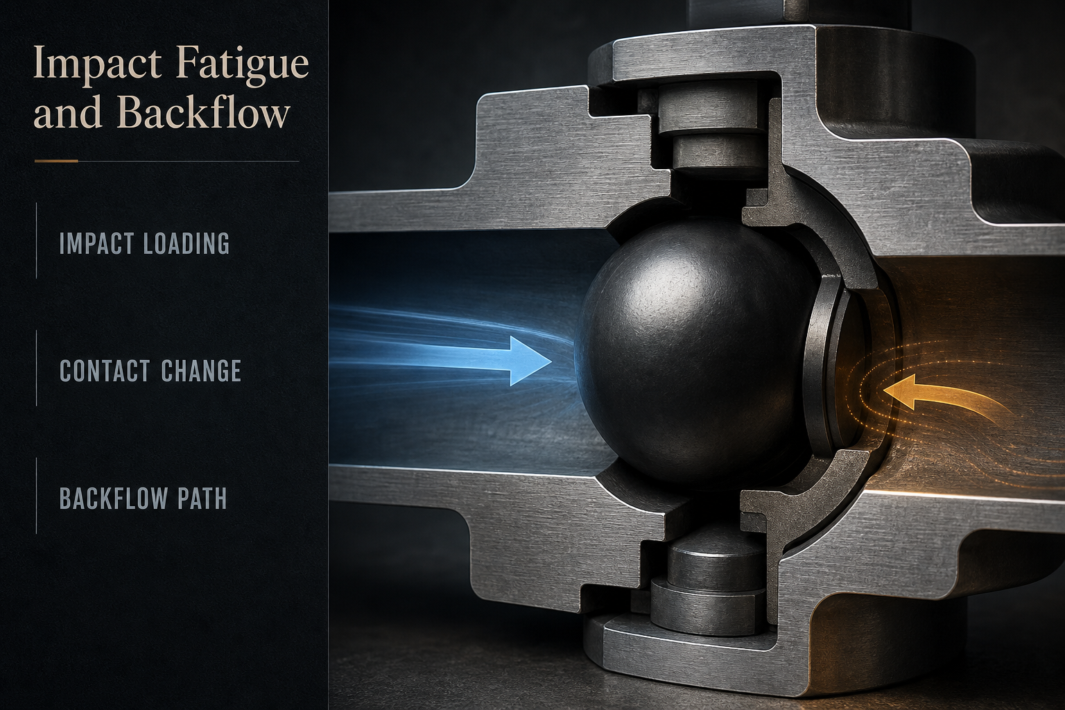
A diaphragm pump moves fluid by reciprocating diaphragm motion. Ball-type check valves are intended to support directional flow by seating against a valve seat when the pressure difference changes direction. The ball, seat, guide, retainer and nearby passage form a functional boundary, but the measured pump response may also include another check valve, a hose, a reservoir, trapped gas, a fixture or an external leakage path.
The first task is therefore to define the boundary being tested. A local ball-and-seat inspection answers a different question from a pump-level flow test. A pressure trace may show a delayed response or reverse movement without identifying whether the cause is incomplete seating, diaphragm timing, line compliance or a remote path. The article treats the pump and valve arrangement generically; no construction, material or duty is assumed.
Table 1. Ball-Valve Boundary Conditions and Possible Responses
| Condition or observation | Possible contributor | Evidence to preserve | What it may indicate | Limitation |
| Normal seating before a symptom | Stable contact under a defined state | Baseline state and test boundary | Reference response | Baseline is not a qualification result |
| Response changes during strokes | Loading, timing, particles or diaphragm state | Stroke context and pressure/flow trace | Condition-dependent response | Cause is not isolated |
| Reverse flow after stopping | Incomplete seating or another path | Stop sequence and boundary continuity | Possible backflow path | One reading does not identify location |
| Ball or seat visual change | Wear, deformation, residue or handling | Pre-cleaning images and component state | Contact condition may have changed | Appearance does not identify mechanism |
| Guide or retainer condition changes | Misalignment, retention or assembly variation | Orientation and maintenance record | Ball motion may be affected | Requires actual geometry review |
How Repeated Seating Events Can Change the Contact Condition
Each seating event can involve relative motion, contact loading and a pressure transition. Over repeated operation, the contact area may remain stable, change gradually or become sensitive to a local mark, particle or alignment condition. A fatigue-like interpretation requires more than the existence of repeated impacts: it depends on the actual load history, geometry, contact response, material behavior and evidence of progressive change. Those inputs are not supplied for a specific pump here.
It is useful to separate reversible dynamics from retained damage. A ball may settle differently during a transition and then recover when the operating state changes. By contrast, a dent, chip, scratch, deformation or altered seating surface may persist. A particle can hold the ball off the seat without being a fatigue crack, while wear can change the contact line without a single high-impact event. Reassembly can also change the result by altering orientation, retention or surface condition.
Sound or vibration may help locate a change in behavior, but neither identifies a fatigue mechanism by itself. A comparison should preserve timing, operating state and test boundary, then connect any physical mark to a plausible contact location. Do not assign an impact count, fatigue life or material limit without a defined duty and supporting evidence.
Ball, Seat, Assembly and Fluid-Compatibility Mechanisms
Ball and seat wear can include abrasion, erosion, adhesive contact, deformation, chipping or other surface change. The relevant mode depends on the fluid, particles, contact motion, pressure history and geometry. A visible ring, polished area or mark can be consistent with repeated contact, but it does not establish whether impact fatigue, wear, contamination or handling produced it. Inspection should preserve the component before cleaning and record the location, shape and relation to the seating interface.
Fluid compatibility is a separate evidence stream. Swelling, softening, embrittlement, permeation, dissolution or surface change require an exposure history and a material-specific assessment. Impact alone does not prove chemical attack, and a material exposure result does not reproduce the full pump duty automatically. If the ball, seat, retainer or nearby seal is exposed to a fluid or cleaning agent, record what is known and leave unknown chemistry marked as not evaluated.
Assembly preload and seating are also independent mechanisms. Orientation, retention, guide condition, surface cleanliness, reuse, tightening practice and reassembly can change the contact response. A symptom observed after maintenance may reveal assembly variation or a pre-existing condition rather than create a new fatigue failure. No universal material, preload, clearance, dimension or service interval can be selected from this general discussion.
Table 2. Alternative Mechanisms Behind Backflow or Changed Valve Response
| Observation or symptom | Possible mechanism | Alternative mechanism to separate | Verification approach | Limitation |
| Reverse flow after pressure transition | Ball not fully seated | Remote line or fixture path | Isolate the tested boundary | Isolation must match the actual setup |
| Response changes with pump motion | Valve timing or diaphragm state | Ball/seat contact change | Compare matched operating states | No operating frequency is assumed |
| Mark on ball or seat | Contact or wear | Particle, residue or handling | Inspect before cleaning and map location | Mark alone is not causal proof |
| Particles or residue observed | Ball held off seat | External contamination or upstream source | Preserve sample and review path | Composition requires suitable analysis |
| Fluid exposure is uncertain | Compatibility-related change | Mechanical impact or assembly variation | Review fluid and material evidence | No material is assumed |
| Symptom follows reassembly | Seating or preload variation | Underlying wear or test variation | Compare assembly records and boundary test | Reassembly can alter evidence |
Separating Backflow Paths from Diaphragm and System Effects
Backflow can be associated with incomplete seating, ball or seat damage, particles, valve timing, pressure reversal or an unintended passage. It can also be mimicked by a line restriction, trapped gas, hose compliance, reservoir behavior, an adjacent check valve or leakage in a fixture. The flow direction and boundary must be verified before a local ball-and-seat diagnosis is accepted.
The diaphragm operating state matters because stroke, deflection, frequency, startup, shutdown, pressure transition and abnormal motion may change the pressure difference presented to a check valve. A changed flow reading during one state does not prove that the valve condition changed. Record whether the pump was running, stopped, priming, draining, warming, pressurized or otherwise transitioning when the symptom appeared. Do not infer dry running, cavitation-like behavior or abnormal motion without evidence.
A useful comparison separates local and system evidence. Inspect the ball and seat while preserving the original state; compare inlet, outlet and external paths; review diaphragm and maintenance history; and repeat a defined boundary test when practical. A pressure drop, noise or reduced flow can guide the next check, but it cannot identify the root cause without controlled context.
Inspection and Validation Workflow After a Changed Valve Response
Begin before cleaning, retorquing or disassembling the valve. Record the symptom, timing, operating state, test boundary, baseline and available maintenance history. Preserve photographs, labels, component orientation and nearby surfaces. If the record is incomplete, mark the uncertainty rather than filling it with a typical pump value.
• Inspect the ball, seat, guide, retainer and passages for distortion, marks, particles, residue and uneven contact; do not convert appearance into material identification.
• Review seating geometry, retention, orientation, surface condition and assembly evidence, including whether the component was reused or reassembled.
• Treat fluid exposure and chemical compatibility as a separate evidence stream and identify the limits of any exposure or compatibility review.
• Compare local ball/seat condition with inlet, outlet and external flow paths; isolate adjacent valves and fixtures where feasible.
• Review diaphragm stroke, frequency, pressure transitions and startup/shutdown state only when those variables are recorded or can be controlled.
• Compare baseline, post-symptom, stabilized and reassembled states only when the test plan makes the comparison meaningful.
• Verify sensor calibration, background, stabilization, detection limit, data handling and acceptance criteria before interpreting a pressure or flow result.
• Classify each conclusion as observed, suspected, confirmed, inconclusive or not evaluated, and state the evidence limitation.
Each method has a different objective. Visual inspection can show a mark but not prove impact fatigue. A pressure trace can show a response but not isolate the ball/seat boundary. A material review can identify a compatibility question but not reproduce the complete pump duty. A flow test can show directional behavior only for its defined boundary and conditions.
Table 3. Inspection and Validation Guide for Diaphragm-Pump Ball-Valve Seals
| Check or test | Objective | Key variable or evidence | What it may indicate | Limitation |
| Pump and diaphragm history | Define the operating state | Stroke, timing and transitions | State-related contributor | History may be incomplete |
| Ball, seat and guide inspection | Locate physical change | Contact area, marks and residue | Changed seating condition | Does not prove cause |
| Seating and dimensional review | Check fit and alignment | Orientation and contact geometry | Misalignment or deformation | Requires suitable reference |
| Fluid compatibility review | Separate chemical effects | Exposure history and material evidence | Possible surface or property change | No material is assumed |
| Particle and residue assessment | Check contact interruption | Location and suitable characterization | Ball held off seat | Appearance is not composition |
| Flow-path isolation | Define local boundary | Adjacent valves, fixtures and lines | Remote path contribution | Setup must be represented |
| Pressure/flow comparison | Compare defined states | Timing, stabilization and calibration | Repeatable state difference | No universal acceptance limit |
| Reassembly verification | Check restored directionality | Assembly record and final boundary | Persistent or removed symptom | Does not prove service life |
Design, Assembly, Operation and Maintenance Controls
Controls should match the mechanism under review. A design review may consider how the ball seats, how the guide or retainer controls motion, how the passage supports flow direction and how particles can reach the contact interface. These are design questions, not proof that a particular geometry is defective. The actual fluid, duty profile, valve arrangement and qualification method must define any change.
Assembly controls should preserve orientation, seating, surface condition and retention evidence. Cleaning and handling should protect the ball, seat and nearby passages from particles or damage. Maintenance records should connect the observed symptom with the component state before and after service. A new ball or seat should not be selected solely because it removes one symptom unless the boundary, mechanism and qualification evidence support the change.
Operation and monitoring controls should record the state in which backflow or reduced pumping response occurs. Where qualification data exist, the duty profile can be compared with the observed pressure, flow and diaphragm behavior. Do not prescribe a universal pressure, temperature, frequency, impact count, material or acceptance limit from this general article. Any control must be qualified for the actual pump, fluid, geometry, assembly and test method.
Qualitative FMEA: Ball-Valve Impact and Backflow Response
The following FMEA is a qualitative screening aid for organizing evidence. It is not field statistics, a product rating or a confirmed failure analysis. It uses no probability, severity score, RPN, impact count, pressure, temperature, material specification, backflow rate, service-life claim or test result.
Table 4. Qualitative FMEA for Ball-Valve Impact and Backflow
| Failure Mode | Cause | Local Effect | System Effect | Detection Method | Control Action |
| Repeated seating load changes contact | Duty or contact condition may vary | Changed seating response | Possible directional-flow change | History and component inspection | Define duty and preserve baseline |
| Ball or seat wear changes interface | Contact, particles or fluid exposure | Incomplete contact | Possible backflow symptom | Visual and dimensional review | Control contamination and review evidence |
| Particle or residue holds ball off seat | Contamination or retained residue | Local standoff | Reverse-flow path | Location and suitable assessment | Protect surfaces and flow path |
| Fluid compatibility concern | Unverified exposure/material response | Surface or property change | Changed sealing response | Exposure and compatibility review | Use qualified material evidence |
| Guide, retainer or seating misalignment | Assembly or geometry variation | Ball motion or seating change | Unstable valve response | Orientation and fit inspection | Control assembly and retention |
| Diaphragm state influences response | Stroke or pressure transition | Different valve loading | State-dependent backflow | Operating-state comparison | Record and control the state |
| External path mimics backflow | Line, fixture or adjacent valve | Local cause misidentified | Wrong corrective action | Boundary isolation | Define tested boundary |
| Measurement error changes interpretation | Calibration or stabilization issue | Apparent response change | Unnecessary replacement | Test-background review | Standardize method and limits |
Conclusion
Impact fatigue is one possible explanation for a changed diaphragm-pump ball-valve response, but suspected backflow does not prove that mechanism. Repeated seating, ball and seat wear, particles, fluid compatibility, assembly preload, diaphragm state, external flow paths and measurement conditions can produce overlapping observations. The most defensible investigation preserves the original operating and component state, defines the tested boundary, compares matched conditions and states the limitation of each inspection or test. Conclusions should remain observed, suspected, confirmed, inconclusive or not evaluated until the evidence supports a narrower claim.
FAQ
Q:What can cause backflow in a diaphragm-pump ball valve?
A:Possible contributors include incomplete seating, ball or seat damage, particles, valve timing, diaphragm state, pressure reversal, an adjacent flow path or a test fixture. The actual boundary and operating state must be checked before naming the cause.
Q:Does suspected backflow prove impact fatigue?
A:No. Backflow is an observation, not a fatigue diagnosis. Repeated seating may contribute to a changed contact condition, but wear, contamination, assembly variation, fluid exposure and system paths must be separated with evidence.
Q:How are ball and seat wear different from impact fatigue?
A:Wear describes a change at the contact interface, while impact fatigue is a possible load-history mechanism. A mark can be consistent with either or with particles or handling; location, history and controlled inspection are needed to distinguish them.
Q:Can particles hold a ball away from its seat?
A:Yes, a particle or residue may interrupt contact and create a reverse-flow path. Its presence does not identify its composition or source, so preserve location and review the upstream, cleaning and handling history.
Q:How can fluid compatibility affect a ball-valve seal?
A:Exposure may be relevant when a material changes through swelling, softening, embrittlement, permeation or surface attack. That possibility requires the actual fluid and material evidence; impact alone does not establish chemical incompatibility.
Q:Why does diaphragm operating state matter during inspection?
A:Stroke, frequency, pressure transition, startup and shutdown can change the load presented to a check valve. A result observed in one state should not be generalized to another without a matched comparison.
Q:What should be preserved before replacing a ball or seat?
A:Preserve the symptom timing, operating state, test boundary, component orientation, photographs, ball and seat condition, particles or residue, fluid history, maintenance records and measurement setup. Replacement can remove evidence.
Q:How should the check-valve boundary and test background be verified?
A:Define which valve, line, fixture and adjacent paths are included, then review calibration, background, stabilization and sensor location. A pump-level result cannot isolate a ball-and-seat boundary without a suitable control plan.
Post time: Sep-15-2026