
Executive Summary
Leak detection in a liquid cooling system is a layered safety function, not a single sensor. A micro-leak may appear first as local wetting or a slow pressure trend. A slow leak may reveal itself through persistent pressure decay, level change, or repeated fluid loss. A sudden rupture can produce rapid pressure loss, abnormal flow, and liquid at a rack, CDU, manifold, or low point. Each condition requires a different detection path and response speed.
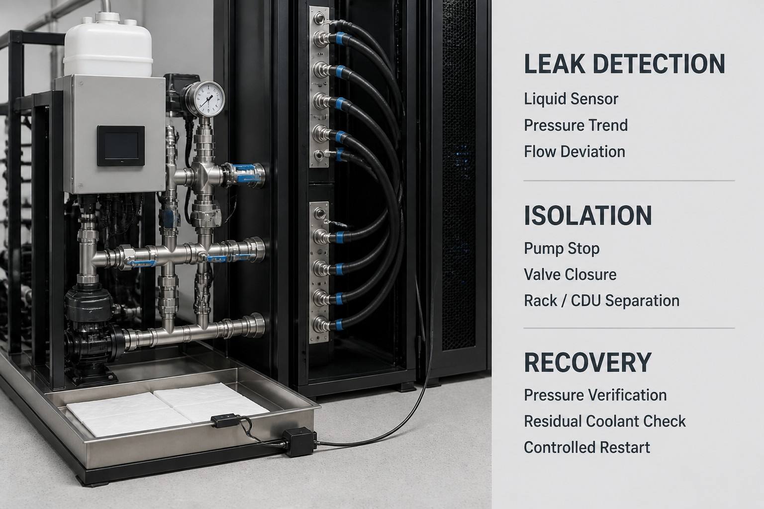
A robust architecture combines liquid-sensing devices with pressure, flow, valve-state, and operational confirmation. Detection coverage should follow the physical risk: rack bottoms and pipe low points for liquid sensors, CDU and manifold areas for local detection, and main and branch circuits for pressure and flow monitoring. After an alarm, the system must confirm the event, stop the pump, isolate the affected section, protect electrical equipment, remove residual coolant, and verify pressure and cleanliness before a controlled restart. No detection system guarantees absolute zero leakage. Actual thresholds depend on loop volume, coolant, design pressure, sensor specification, and the consequences of exposure.
Leak Types and Failure Physics
Micro-leakage is a very low-rate loss that may remain localized or evaporate before forming a visible drop. Slow leakage produces a measurable trend over time, such as pressure decay, liquid-level change, or repeated top-up demand. Sudden rupture is a high-rate event caused by a failed hose, pipe, connection, or component and normally requires immediate automatic action. The response grade should be based on leak rate, location, electrical exposure, available isolation, and the time required to stop fluid movement—not on a universal volume threshold.
Table I: Liquid Cooling Leak Types and Early Warning Signals
|
Leak type |
Early signal |
Detection method |
Potential impact |
Response level |
| Micro-leakage | Local wetting, intermittent pressure trend, residue | Point sensor, cable, pressure trend, inspection | Progressive damage or hidden moisture | Investigate and monitor; isolate if confirmed |
| Slow leakage | Persistent pressure decay, level loss, recurring refill | Pressure, level, flow deviation, point sensor | Loss of cooling margin and expanding wet area | Controlled isolation and maintenance response |
| Sudden rupture | Rapid pressure loss, flow change, liquid alarm | Pressure, flow, liquid sensor, interlock | Equipment exposure and rapid loop depletion | Immediate pump stop and section isolation |
The three categories describe response dynamics, not universal leak-rate limits. Thresholds must be set from loop volume, pressure, coolant, sensor resolution, and electrical exposure.
Detection Architecture and Sensor Placement
Liquid-sensing cable provides broad coverage along rack bases, CDU perimeters, and pipe low points, while point sensors provide fast local confirmation at a known hazard. Pressure-drop monitoring is effective for detecting a loss of containment or a change in loop state, but it cannot identify the physical location by itself. Flow-rate deviation can reveal a rupture, blockage, or pump problem and should be interpreted with pressure and valve status. Visual inspection remains useful at UQD interfaces, maintenance panels, hose joints, and transparent sections, but it is not continuous protection.
Sensor placement should follow where liquid can collect and where a leak can reach sensitive equipment. Put liquid detection at rack bottoms, CDU bases, manifold low points, service panels, and pipe low points. Use pressure and flow sensors across the main loop and critical branches. Use local point sensors where a cable cannot follow the geometry or where a small protected volume has high consequence. Avoid false alarms by separating leak sensing from condensation, cleaning fluid, planned draining, and maintenance residue; confirm alarms through an independent signal or visual check when the event is not rapidly escalating.
Alarm logic should distinguish a single unconfirmed signal from a corroborated event. A point sensor may be wet because of planned draining, while a pressure trend may be caused by temperature change or trapped air. Conversely, a very small leak may produce no immediate pressure response while slowly wetting a low point. The control system should log the initiating signal, associated pressure and flow state, valve position, pump status, and operator confirmation. Periodic proof tests should deliberately exercise sensors, alarm paths, valve feedback, and pump-stop interlocks so that a healthy display is not mistaken for a tested safety function.
Table II: Leak Detection Method Selection Matrix
|
Method |
Response speed |
Coverage |
False-alarm risk |
Maintenance |
Suitable location |
| Liquid-sensing cable | Fast after contact | Long routed path | Condensation, residue, routing gaps | Test continuity and clean path | Rack base, CDU perimeter, low points |
| Point liquid sensor | Fast at fixed point | Local only | Splash or planned draining | Functional test and cleaning | CDU, manifold, service panel, UQD area |
| Pressure-drop monitoring | Trend or rapid event | Whole isolated volume | Temperature, trapped air, pump state | Calibration and baseline review | Main loop and isolated branches |
| Flow-rate deviation | Fast when flow changes | Measured circuit | Pump or valve faults resemble leaks | Calibration and trend review | CDU outlet, rack branch, cold-plate loop |
| Visual inspection | Human response | Line of sight only | Operator inconsistency | Scheduled inspection | Joints, interfaces, transparent sections |
No method detects every leak mode. Layered detection reduces blind spots by combining direct liquid evidence with hydraulic and operational evidence.
Emergency Isolation and System Recovery
Emergency response should be designed as a sequence with an action and a confirmation at every step. Alarm confirmation means validating the sensor state and checking for an independent hydraulic or visual signal, but a rapidly escalating event should not wait for a lengthy investigation. Pump shutdown must be confirmed by actual motor status and flow decay, not only by a control command. Valve isolation must be confirmed by valve position feedback and the expected pressure response; a displayed closed command is not proof of a closed hydraulic path.
After isolation, separate the affected rack, CDU branch, or manifold section from healthy equipment. Protect electrical interfaces before handling residual coolant. Remove liquid from low points and equipment surfaces using an approved procedure, then inspect for migration into adjacent areas. Before restart, perform the project-defined pressure test, check for continuing pressure decay, inspect sensor and valve function, confirm cleanliness after the incident and recovery work, and verify that the intended flow path is restored. Any response time or pressure threshold used in a procedure is an illustrative engineering example unless supported by the system design and test record.
Table III: Emergency Isolation Sequence
|
Step |
Immediate action |
Control objective |
Confirmation signal |
Escalation condition |
| Alarm confirmation | Validate sensor and independent signal | Distinguish event from nuisance alarm | Sensor state plus pressure, flow, or inspection | Signal disagreement or rapid worsening |
| Pump shutdown | Stop affected pump or circuit | Stop active fluid transport | Motor status and flow decay | Pump continues or flow remains high |
| Valve isolation | Close upstream and downstream isolation | Limit leak volume and spread | Valve feedback and pressure response | Valve fails, leaks through, or feedback is absent |
| Rack or CDU separation | Isolate affected branch or module | Protect healthy sections | Section pressure and flow state | Isolation boundary cannot hold |
| Electrical protection | Protect exposed power and electronics | Prevent secondary electrical hazard | Authorized inspection status | Liquid reaches energized equipment |
| Residual coolant removal | Drain, absorb, or recover liquid | Prevent migration and recontamination | Dryness and surface inspection | Hidden low point or trapped liquid remains |
| Pressure and cleanliness verification | Test boundary and inspect recovery path | Confirm safe physical condition | Stable pressure, clean sample, inspection | Decay, residue, or contamination persists |
| Controlled restart | Restore flow in stages | Prevent recurrence and shock response | Flow, pressure, sensor, and temperature trends | Any abnormal trend or alarm returns |
Every step requires both an execution command and a confirmation signal. Recovery is not complete until the isolated boundary, residual fluid, pressure state, and cleanliness condition are verified.
Leak management should be part of normal data-center operations, not an emergency document stored separately from the maintenance system. Record sensor proof tests, valve exercises, pump-stop tests, alarm acknowledgements, pressure-test results, and recovery decisions as planned maintenance evidence. Periodic drills should use controlled test conditions and confirm that operators can identify the affected boundary, protect electrical equipment, and restart only after the required release checks are complete.
FMEA Risk Analysis
FMEA should separate detection failure, isolation failure, and recovery failure. A false alarm can create unnecessary service activity, but a missed micro-leak can allow hidden moisture to spread. An isolation valve may receive a close command yet fail to seal. A pump may remain active because a control or power fault prevents shutdown. Residual coolant can create a second exposure after the visible leak is removed, and an incorrect restart can re-pressurize an unverified boundary.
Table IV: Leak Detection FMEA and RPN Analysis
|
Failure mode |
Effect |
Current control |
S |
O |
D |
Illustrative RPN |
Recommended action |
| Sensor failure | Leak remains undetected | Continuity and functional test | 9 | 2 | 6 | 108 | Use redundant or independent signals |
| Unnecessary shutdown or service | Alarm confirmation logic | 5 | 4 | 3 | 60 | Separate condensation and maintenance states | |
| Missed micro-leak | Hidden moisture and progressive damage | Trend review and inspection | 8 | 3 | 7 | 168 | Add local sensing and periodic pressure test |
| Isolation valve failure | Leak volume and spread increase | Position feedback | 9 | 2 | 6 | 108 | Test actual isolation and pressure response |
| Pump shutdown failure | Fluid continues moving | Motor interlock and status | 9 | 2 | 5 | 90 | Test stop path under operating conditions |
| Residual coolant not removed | Secondary exposure or recontamination | Drain and inspection procedure | 7 | 3 | 6 | 126 | Inspect low points and repeat cleanliness check |
| Incorrect restart | Leak or damage recurs | Controlled restart checklist | 9 | 2 | 6 | 108 | Require signed pressure, sensor, and flow release |
RPN values are illustrative engineering examples using S x O x D. Project procedures must define scoring scales, thresholds, and ownership.
Engineering FAQ
Q:How early can a liquid cooling system detect a micro-leak?
A:It depends on leak rate, sensor location, loop volume, pressure state, coolant behavior, and signal resolution. Local liquid sensing can detect contact quickly at the protected point, while pressure and flow trends may require enough accumulated change to separate a leak from temperature, trapped air, or pump-state effects. Use layered detection and periodic pressure testing rather than assuming one sensor has a universal detection time.
Q:Which detection method is suitable for a server rack and a CDU?
A:Use liquid-sensing cable or point sensors where liquid can collect at rack bases, CDU perimeters, low points, and service panels. Add pressure and flow monitoring to the main loop and critical branches. The final selection depends on geometry, liquid volume, sensor specification, condensation conditions, and the consequence of exposure.
Q:What should happen immediately after a leak alarm?
A:Confirm the alarm without delaying a rapidly escalating response, stop the affected pump, isolate the upstream and downstream boundary, separate the rack or CDU branch, protect electrical equipment, and remove residual coolant. Confirm each action through actual motor status, valve feedback, pressure response, and inspection.
Q:How should a liquid cooling loop be verified before restart?
A:Complete the project-defined pressure test, inspect for residual coolant and contamination introduced during repair, verify sensor and valve function, confirm stable flow and pressure, and restart in controlled stages while monitoring temperature and alarm trends. Do not restart solely because the visible liquid has been removed.
Post time: Aug-15-2026