
Executive Summary
Gas management in a direct liquid cooling loop is a circulation-reliability task, not only a thermal-management task. Dissolved gas, entrained air and free gas pockets can interrupt flow, disturb pump inlet conditions, destabilize heat transfer, bias flow measurements and create local temperature excursions. The same gas load can also change how liquid wets O-rings, gaskets, valve seats, shaft seals, quick-disconnect seals, plate heat exchanger gaskets and cold-plate interfaces.
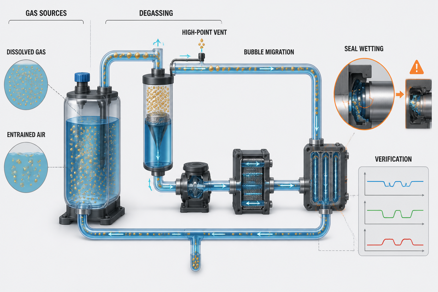
The engineering sequence is gas source, gas removal, gas transport and gas–liquid interface control. Degassing reduces dissolved gas and the initial gas load; venting removes free gas that has already collected. Neither action alone proves that a loop is leak-free or permanently free of air. Filling practice, system geometry, pressure transients, reservoir behavior and maintenance determine whether gas returns.
A defensible verification record combines pressure, flow, temperature, liquid level, vibration, visual observation and post-maintenance checks. The objective is not to claim zero bubbles under every condition, but to keep gas below the level that disrupts circulation, heat transfer, measurement stability or seal wetting.
Gas Sources and Bubble Types in Liquid Cooling Loops
Dissolved gas is gas held in the coolant at molecular scale. It may be released when temperature rises, pressure falls or the coolant enters a low-pressure region. Entrained air consists of dispersed bubbles transported by the liquid, often introduced during filling, mixing, pump operation or maintenance. A free gas pocket is a larger accumulation that occupies a high point, blind branch, reservoir region or other low-flow volume. Microbubbles can migrate with the flow, coalesce or attach to surfaces before reaching a separation or venting location.
Vapor bubbles are formed when local pressure and temperature allow the liquid to vaporize; they are not equivalent to air ingress. Air can also enter through a microleak on a suction-side or low-pressure boundary without producing an obvious external coolant leak. Flexible hose motion, repeated topping-up, reservoir gas exchange and incomplete post-maintenance venting are additional sources. A diagnosis should identify the gas state and source before selecting a remedy.
Table I: Gas Type, Source and System Risk
|
Gas type |
Main source |
Typical location |
System effect |
Detection signal |
Control method |
| Dissolved gas | Temperature rise, pressure reduction or coolant exposure | Reservoir, warm return and low-pressure zones | Microbubble release and unstable readings | Trend change after pressure or temperature shift | Degassing, controlled filling and pressure management |
| Entrained air | Initial filling, mixing, pump start or maintenance | Lines, manifolds and flexible hoses | Flow disturbance and heat-transfer variation | Visible bubbles, noise or flow fluctuation | Slow filling, staged venting and low-load circulation |
| Free gas pocket | Buoyancy and poor geometry | High points, risers and blind branches | Flow interruption or trapped volume | Level change, intermittent flow or thermal deviation | High-point venting and geometry correction |
| Microbubbles | Gas release, shear or repeated recirculation | Small passages, heat exchangers and cold plates | Measurement bias and surface attachment | Unstable flow or scattered visual bubbles | Inline separation and controlled residence time |
| Vapor bubble | Local pressure and temperature condition | Pump inlet or restrictive low-pressure region | Possible inlet disturbance and noise | Vibration, acoustic change and pressure fluctuation | Correct gas load and operating condition; verify separately from air removal |
| Air ingress | Microleak, loose connection or suction-side negative pressure | Pump suction, vent valve or service joint | Repeated gas return and seal wetting loss | Reservoir level drift with recurring bubbles | Locate ingress path, repair boundary and repeat verification |
The table separates gas origin from symptom. A visible bubble does not identify whether the cause is dissolved-gas release, entrainment, vapor formation or air ingress; the pressure, temperature and maintenance history are required for interpretation.
Degassing and Venting Mechanisms
Vacuum degassing lowers the dissolved-gas load before or during filling by exposing coolant to reduced pressure. Controlled vacuum filling can reduce the amount of air introduced while the loop is being filled, but it does not remove gas generated later by temperature or pressure changes. Inline degassing or gas separation acts on circulating coolant and is useful when gas release continues during operation. Its effectiveness depends on residence time, flow distribution, separator design and maintenance condition.
Automatic air vents and manual high-point vents remove free gas collected at selected locations. They cannot remove all dissolved gas and may themselves become leakage or air-ingress paths if the valve, float, seal or isolation arrangement is unsuitable. Expansion tanks support gas–liquid separation when their geometry and operating level allow it. High-point venting works only when the piping layout actually guides gas to the vent.
No single method is a universal solution. The method must match the gas state, source, loop geometry, operating sequence and maintenance capability.
Table II: Degassing and Venting Method Comparison
|
Method |
Main target |
Suitable location |
Main benefit |
Main limitation |
Maintenance concern |
| Vacuum degassing | Dissolved gas and initial gas load | Fill station or service skid | Reduces gas before circulation | Does not remove later ingress or release | Vacuum integrity and coolant compatibility |
| Controlled vacuum filling | Filling air and gas pockets | Reservoir and loop filling point | Limits air introduced during fill | Requires controlled connections and sequence | Check isolation, hoses and fill records |
| Inline degassing | Dissolved and microbubble load during flow | Return line or separation module | Acts while the loop operates | Performance depends on flow and residence time | Inspect separator, filter and drain path |
| Automatic high-point vent | Free gas pocket | Designed high points and risers | Continuous removal at selected points | Cannot remove dissolved gas; may admit air | Check valve seat, float and isolation boundary |
| Manual venting | Free gas at known service points | High points, manifolds and heat exchangers | Simple and direct for maintenance | Operator dependent and condition specific | Control opening, collection and re-tightening |
| Expansion-tank separation | Gas–liquid exchange in reservoir | Reservoir or expansion volume | Provides residence time and level buffering | Poor geometry can re-entrain gas | Maintain level, baffle condition and gas space |
The method comparison is a selection aid, not a performance guarantee. A method should be accepted only after the resulting pressure, flow, temperature and gas observations are stable under the defined operating sequence.
Bubble Transport and Accumulation
Gas transport is controlled by the balance between buoyancy, liquid velocity, pressure variation, bubble size and local geometry. A bubble may follow the liquid through a straight run, rise into a high point, split in a manifold, coalesce in a low-flow branch or attach to a surface. Vertical risers can either carry gas upward or retain it at a crest depending on flow direction and vent location.
Blind branches, elbows, flexible hoses, manifolds and small-diameter passages create regions where the local velocity is insufficient to sweep gas away. Plate heat exchangers and cold plates can retain gas at upper channels or headers when installation attitude and venting do not match the internal path. A pump suction line is especially sensitive because gas entering the inlet can change the local mixture, pressure signal and vibration response. These effects may resemble a pump problem, but the gas source and transport path must be checked first.
System posture matters during filling and maintenance. A loop that vents adequately in its installed position may retain gas when a hose, cold plate or exchanger is rotated. The commissioning procedure should therefore specify the physical configuration used for filling, venting and restart verification.
Gas–Liquid Interface and Sealing Risks
A seal interface is designed around a controlled contact load and a compatible fluid environment. When gas repeatedly replaces liquid at the interface, the local lubrication state, heat removal and pressure distribution can change. This is most significant for dynamic shaft seals, pump mechanical seals and moving valve or diaphragm interfaces, but static seals can also be affected by pressure cycling, local heating, contamination and loss of continuous wetting.
Bubble passage may create intermittent dry contact rather than continuous dry running. The distinction matters: short repeated events may produce friction heat, wear particles and surface instability before a measurable external leak appears. Gas compression and expansion can also cause pressure oscillation across a seal. If a microleak already exists, the pressure cycle may allow air ingress on one part of the cycle and coolant escape on another.
The risk is not universal. Seal geometry, material, surface finish, pressure, temperature, speed, fluid viscosity, exposure duration and particle control determine whether gas exposure remains tolerable or becomes a reliability threat.
Table III: Gas–Liquid Interface Sealing Risk Matrix
|
Seal location |
Gas-related mechanism |
Local effect |
Possible system symptom |
Verification method |
Recommended control |
| O-ring | Intermittent wetting and pressure cycling | Friction change or local abrasion | Small recurring bubbles or level drift | Pressure hold, visual inspection and teardown | Maintain liquid coverage and control compression |
| Static gasket | Gas pocket and thermal or pressure cycling | Uneven contact load or contamination path | Intermittent seepage or temperature deviation | Boundary pressure test and surface inspection | Remove trapped gas and verify flange condition |
| Dynamic shaft seal | Repeated bubble passage at sliding face | Dry contact, heat and wear debris | Vibration, noise or gradual leakage | Vibration trend, leak check and face inspection | Stabilize inlet condition and protect lubrication |
| Valve or diaphragm seat | Gas pocket across contact line | Unstable closure or local heating | Flow oscillation or incomplete isolation | Position test and pressure differential check | Vent trapped volume and verify seating |
| UQD or service seal | Air ingress during connection or trapped gas | Temporary loss of wetting and contamination risk | Bubbles after reconnection or level change | Connection inspection and restart observation | Control connection sequence and venting |
| Plate heat exchanger gasket | Gas accumulation near header or plate edge | Local dry area and thermal nonuniformity | Temperature fluctuation or flow imbalance | Differential pressure and thermal comparison | Orient, vent and maintain stable flow |
| Cold-plate seal | Gas pocket near header or manifold | Reduced local wetting and heat transfer | Local temperature rise or unstable flow | Thermal map, flow trend and visual check | Use geometry-compatible venting and restart checks |
The matrix links gas behavior to seal function without claiming that every bubble causes immediate failure. The practical control objective is to prevent persistent gas exposure at interfaces where liquid wetting, heat removal or contact stability is part of the seal design.
Detection and System Verification
Gas retention often produces a combination of unstable flow, temperature fluctuation, pressure noise, reservoir level movement and intermittent acoustic or vibration signals. External leakage is more likely to produce visible wetting, a sustained level decrease or a pressure trend that cannot be explained by gas redistribution. Air ingress may show recurring bubbles after the loop has been vented, especially near suction-side joints or vent valves. Coolant evaporation and instrument error require separate checks rather than being assumed to be gas-related.
Verification should compare signals over a defined operating sequence. Record pressure trend, flow stability, supply and return temperature, differential pressure, liquid level, pump vibration, acoustic indication and visual bubble behavior. Where justified by the system design, coolant sampling or dissolved-gas monitoring can distinguish a changing fluid condition from a mechanical ingress path. A thermal-performance comparison can show whether gas pockets are affecting a cold plate or heat exchanger, but it does not identify the gas source by itself.
Post-maintenance verification should include a controlled venting step, low-load circulation, inspection of high points and service joints, restart observation and a record of stable measurements. The acceptance condition must be tied to the actual system design; no universal bubble count, venting time or pressure value should be assumed.
Maintenance and Operating Procedure
Initial filling should use a controlled path that minimizes turbulence and prevents air from being folded into the coolant. Where the system permits, vacuum filling or pre-degassing can reduce the initial gas load. During filling, open the intended high-point vents in a controlled sequence and protect the vent path from becoming a permanent air-ingress route.
Startup should begin with a circulation condition that allows gas to move toward designed separation or venting locations without creating an unstable pump inlet condition. Observe the reservoir level, flow signal, temperature response, vibration and visible bubbles before increasing load. After maintenance or coolant replacement, repeat the defined fill, vent, circulate and restart sequence rather than relying on topping-up alone.
Repeated topping-up is a diagnostic signal. It may indicate external leakage, gas redistribution, evaporation, an incorrect reservoir level or air entering through a low-pressure boundary. Inspect filters and strainers for wear debris, confirm vent-valve integrity, check flexible hose posture and review the maintenance connection sequence. Record what was changed and which measurements returned to stable values.
FMEA Risk Analysis
The following risk rankings are illustrative engineering assessments, not field statistics. They are intended to connect gas-management failures with local seal effects and system-level symptoms. The ranking should be recalculated with actual occurrence, severity and detection data from the specific loop.
Table IV: Bubble Management FMEA and Illustrative Risk Ranking
|
Failure mode |
Cause |
Local effect |
System effect |
Detection method |
Risk ranking |
Corrective action |
| Incomplete initial degassing | Air retained during filling | Entrained gas reaches interfaces | Unstable flow and temperature | Visual, flow and pressure trend | High | Improve filling and verify vent sequence |
| High-point air pocket | Vent absent, blocked or misplaced | Flow area partly occupied | Flow interruption or local overheating | Level, thermal and visual check | High | Add or correct vent path and orientation |
| Air ingress through microleak | Suction-side joint or vent boundary | Recurring gas at seal or inlet | Level drift and intermittent leakage | Pressure hold and ingress isolation | High | Repair boundary and repeat test |
| Blind-branch accumulation | Low flow and poor geometry | Gas remains trapped | Delayed restart or measurement error | Geometry review and purge test | Medium | Modify routing or provide service vent |
| Loss of seal wetting | Gas repeatedly replaces coolant | Friction and heat increase | Wear, vibration or intermittent leak | Trend and seal inspection | High | Stabilize gas load and inspect interface |
| Bubble passage through dynamic seal | Entrained gas at sliding face | Dry-contact events and debris | Progressive seal degradation | Vibration, acoustic and leak check | High | Protect inlet condition and lubrication |
| Unstable pump suction | Gas pocket or inlet mixture change | Pressure and flow fluctuation | Circulation instability | Pressure, vibration and flow trend | High | Remove gas source and review inlet path |
| Vent valve leakage | Damaged seat or poor closure | Air entry or coolant loss | Recurring gas and level change | Isolation and pressure test | Medium | Repair or replace vent boundary |
| Incorrect vent location | Vent not at actual gas crest | Gas bypasses vent | Persistent trapped gas | Posture and geometry review | Medium | Relocate or add vent at verified high point |
| Maintenance-induced air entry | Open system, poor sequence or topping-up | New entrained gas load | Repeated commissioning symptoms | Maintenance record and restart check | Medium | Standardize connection and filling steps |
| Gas-induced measurement instability | Bubbles at sensor or flow section | Signal bias or noise | False diagnosis and control action | Compare instruments and visual state | Medium | Vent sensor region and validate measurement |
| Flow interruption overheating | Gas pocket blocks or diverts flow | Local coolant contact decreases | Local temperature excursion | Thermal map and flow comparison | High | Remove pocket and verify circulation |
FMEA is useful when each risk has a physical cause, an observable signal and a corrective action. A high ranking does not prove failure; it identifies where the loop should receive tighter design review and verification.
Conclusion
Liquid cooling loop bubble management begins with identifying how gas enters or forms, then matching degassing and venting to the actual gas state and loop geometry. Degassing reduces dissolved gas and initial gas load. Venting removes free gas that has collected in high points, risers, branches, reservoirs or equipment headers. Neither is effective if filling, maintenance, pressure conditions or system posture continuously reintroduce gas.
Gas transport determines where the problem appears: at a pump inlet, a heat exchanger header, a cold-plate manifold, a sensor location or a seal interface. Persistent gas–liquid interfaces can change wetting, friction, heat removal and contact stability, but the outcome depends on seal type, material, pressure, temperature, speed and exposure duration. Reliable operation therefore requires coordinated control of fluid circulation, geometry, separation, venting, measurement and seal verification.
Engineering FAQ
Q:What is the difference between dissolved gas and entrained air in a liquid cooling loop?
A:Dissolved gas is held within the coolant at molecular scale and may be released when pressure or temperature changes. Entrained air exists as dispersed bubbles that are transported by the liquid. They require different controls: degassing addresses dissolved load, while venting and separation address free or entrained gas.
Q:Why do bubbles accumulate at high points and low-flow areas?
A:Buoyancy drives gas upward, while low local velocity provides insufficient force to carry it away. Crests, blind branches, manifolds, flexible hoses and equipment headers can therefore retain gas, especially when the installed posture does not match the vent path.
Q:How does incomplete degassing affect liquid cooling seals?
A:It increases the chance that gas repeatedly replaces liquid at a seal interface. The resulting change in wetting and heat removal can increase friction, local temperature, wear debris or intermittent leakage. The risk depends on seal type and exposure conditions.
Q:Can automatic venting remove all gas from a liquid cooling system?
A:No. Automatic vents remove free gas at their designed locations. They do not necessarily remove dissolved gas, microbubbles outside the vent path or air entering through a separate microleak. Verification must include the actual circulation and maintenance sequence.
Q:How can air ingress be distinguished from normal coolant level changes?
A:Air ingress is more likely when recurring bubbles, level drift or pressure changes appear after venting or during low-pressure operation. Compare the level trend with temperature, pressure, maintenance activity and external wetting, then isolate suspected joints and vent boundaries.
Q:What should be checked after maintenance or coolant replacement?
A:Check the filling path, high points, vent valves, service joints, reservoir level, flow stability, pressure trend, temperature response, vibration and visible bubbles. Complete a controlled circulation and restart verification before returning to the normal load sequence.
Post time: Aug-26-2026