
Executive Summary
LNG cryogenic valve sealing is a coupled thermal, mechanical and fluid-boundary problem. Valve body, bonnet, stem extension, seats, stem packing, glands, body-bonnet gaskets and end connections each protect a different leakage path. Reliability depends on thermal-contraction compatibility, seat contact stability, packing compression, stem alignment, stem friction, cooldown and warm-up behavior, pressure cycling and low-temperature verification.
A leak cannot be assigned to “low-temperature material failure” without identifying the path. Seat, stem-packing, body-bonnet and end-connection leakage, fugitive emission, permeation, condensation, frost and test-system pressure decay require different evidence. Metal, polymer and composite elements also change dimensions and recovery differently, while stem movement adds friction and wear.
An ambient pressure test or static hold is only one initial condition. It does not alone establish sealing after cooldown, repeated stem movement, pressure reversal, thermal cycling or warm-up. Verification should combine low-temperature pressure and seat tests, stem-packing leakage checks, actuator torque or thrust monitoring, controlled cooldown, cycling, pressure-decay interpretation and post-test inspection.
LNG Cryogenic Valve Sealing Architecture
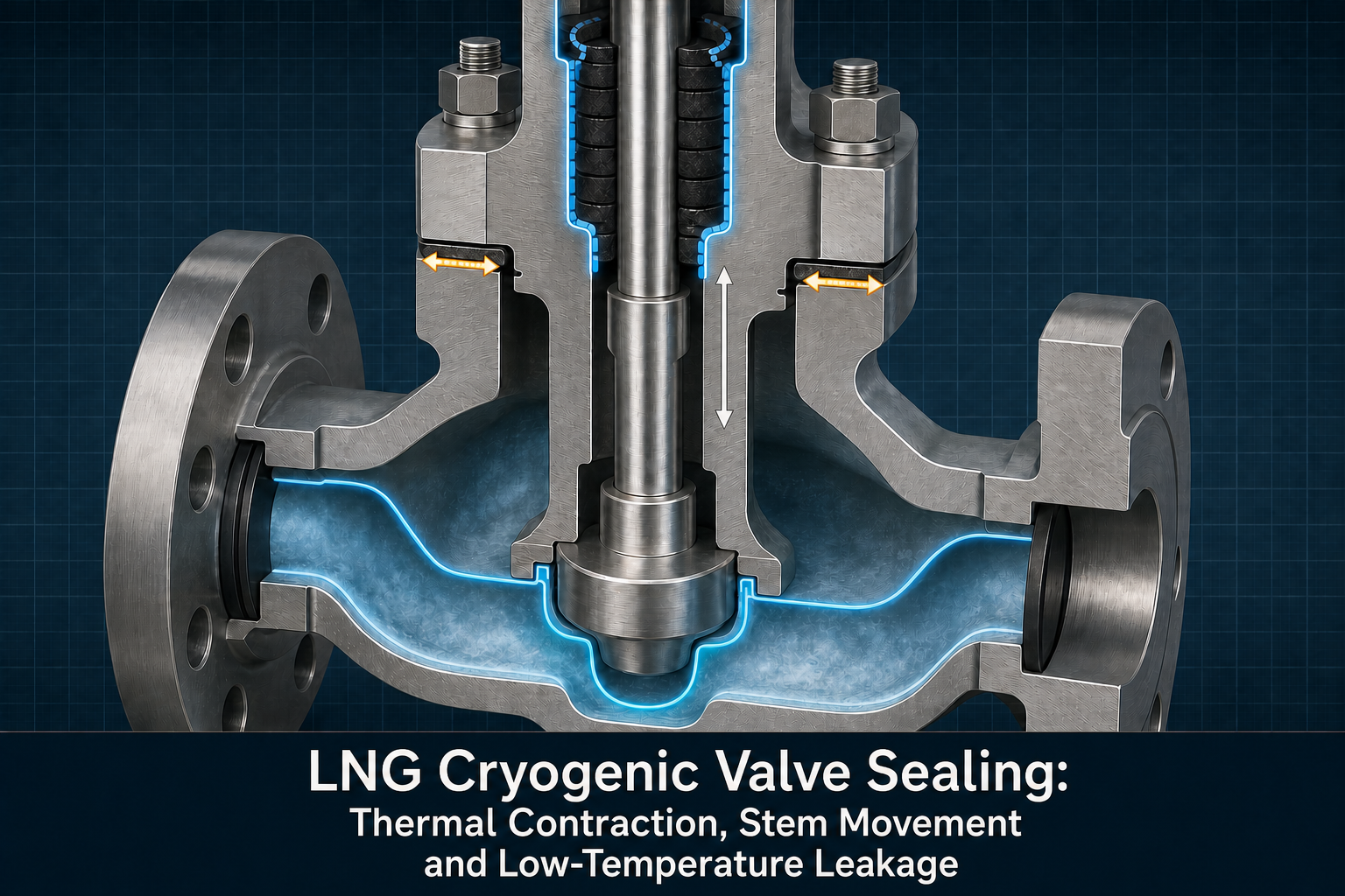
The internal seat seal controls flow through a closed valve. Stem packing limits release along the moving stem. The body-bonnet gasket maintains a static pressure boundary, while the end-connection seal maintains the interface to connected equipment. An extended bonnet or stem extension separates the packing region from the coldest zone but also creates a temperature gradient along the stem and through the bonnet. The actuator interface adds a functional boundary: travel, torque or thrust must be sufficient without imposing damaging friction on the packing or seat.
These boundaries can fail independently. No external wetting does not exclude seat leakage. Frost may reflect cold surfaces or condensation while masking a leak, and pressure decay may reflect gas temperature, test volume, instrument resolution or actual leakage. Identify the path using orientation, pressure direction, temperature history, stabilization time and measurement method.
Table I: LNG Cryogenic Valve Sealing Zones and Functions
|
Sealing zone |
Sealing component |
Adjacent medium |
Main function |
Typical failure risk |
Verification focus |
| Seat boundary | Seat and closure element | Cryogenic fluid and valve cavity | Internal shutoff | Seat internal leakage or particle damage | Low-temperature seat test and pressure direction |
| Stem boundary | Packing, gland and stem | Internal fluid and atmosphere | Limit moving-stem release | Packing leakage, wear or friction increase | Stem leak test and stem cycling |
| Body-bonnet joint | Gasket or metal joint | Process fluid and exterior | Static pressure containment | Joint leakage or contraction loss | Low-temperature external test |
| End connection | Flange or end seal | Valve and connected line | Contain line interface | Connection leakage or load redistribution | Connection pressure and thermal test |
| Gas-side emission boundary | Packing, joints and seals | Gas space and atmosphere | Limit fugitive release | Gas leakage or measurement escape | Helium or emission check |
| Actuator interface | Stem drive and linkage | Actuator and valve internals | Complete intended travel | Under-travel, overload or stall | Torque or thrust and travel record |
A sealing review should map each component to a specific boundary. Combining seat, packing and joint performance into one general “valve leakage” result hides the corrective action required.
Thermal Contraction and Sealing-Interface Stability
During cooldown, metallic parts, polymer seats, packing and composite elements can change dimensions at different rates. Differential contraction changes interference, contact width, gap, gland displacement and local stress. Contraction alone does not prove leakage; geometry, preload, recovery, pressure direction and temperature gradient determine the result.
Thermal mismatch can reduce contact pressure in one region while increasing compression or extrusion risk in another. Hardening, embrittlement or reduced recovery may limit compensation. A cold stem beside a warmer packing and actuator region can also produce a friction gradient. These effects are architecture-specific, not universal contraction or leakage values.
Any dimensional calculation is an illustrative engineering example. Actual results require valve geometry, material data, temperature profile, pressure, contact model and preload. The design question is whether contact and recovery remain adequate through cooldown, operation, cycling and warm-up.
Stem Movement, Friction and Packing Response
Stem packing is a dynamic seal. Translation or rotation changes the contact path while stem surface condition, straightness, alignment, packing compression and gland load control the available sealing reserve. At low temperature, altered hardness, recovery and friction can increase stick-slip, operating force or wear. Packing that is too loose may leak externally; packing that is too tight may increase actuator torque or thrust, prevent full travel, score the stem or accelerate wear.
The actuator may complete a command while packing condition deteriorates. Correlate torque or thrust, travel, temperature, pressure, cycles and external leakage. Treat scratches, particles, eccentricity, gland adjustment and misalignment as separate contributors, not simply material incompatibility.
Seat Sealing Under Cryogenic and Pressure-Cycling Conditions
Seat performance depends on contact pressure, material response, pressure direction, closure geometry, surface condition, particles and repeated opening. Pressure-assisted sealing may improve contact in one direction and reduce it after reversal. Cooldown, trapped liquid, local deformation and warm-up recovery can change the closed condition without changing valve position.
Separate seat internal leakage from stem-packing, body-bonnet and end-connection leakage. A room-temperature cutoff pass may not persist after cooldown or pressure cycling. Inspect for scoring, particles, deformation, embrittlement, extrusion and uneven contact, linked to pressure and temperature history.
Cooldown, Warm-Up and Thermal-Pressure Cycling
Cooldown, cryogenic operation, stem actuation, pressure cycling and warm-up can create different sealing states. Temperature gradients change dimensions and properties; pressure ramps change seat and joint load; movement changes packing friction and wear. Warm-up may restore recovery while exposing damage or load loss.
Testing should reproduce the cooldown procedure, pressure changes, thermal gradients, stem-cycle profile and stabilization periods. Do not convert laboratory cycle counts into universal field life. Confirm that the mechanism is preserved and leakage, travel, torque or thrust remain within valve-specific requirements.
Low-Temperature Leakage and Functional Verification
Verification should follow the suspected path. Ambient pressure testing does not replace low-temperature testing, and a seat test does not replace a stem-packing test. Helium can reveal small paths but does not establish service life. Interpret pressure decay with gas state, test volume, temperature change, stabilization time and instrument resolution.
Document frost or condensation with surface temperature and leakage evidence; it may reflect a cold surface or obscure a release path. Stem-cycle testing should record torque or thrust, travel, cycle condition and external leakage. Warm-up inspection and teardown can identify packing damage, seat marks, joint separation, particles or scoring.
Table II: Thermal Contraction, Stem Movement and Leakage Risk Matrix
|
Operating factor |
Primary sealing effect |
Secondary effect |
Potential failure mode |
Required measurement |
Main limitation |
| Cooldown | Dimensional contraction and contact change | Material hardening or recovery loss | Seat or joint leakage | Temperature, pressure and leak trend | Rate and gradient are valve-specific |
| Differential contraction | Gap or interference redistribution | Local stress concentration | Contact loss or extrusion | Geometry and contact inspection | Nominal material data is insufficient |
| Stem movement | Dynamic friction and wear | Gland-load variation | Packing leakage or high torque | Torque or thrust, travel and leak | Static test misses motion effects |
| Pressure cycling | Seat and joint load reversal | Particle movement or extrusion | Internal or external leakage | Pressure direction, ramp and leak | Cycle profile must match service |
| Thermal cycling | Repeated expansion and recovery | Fastener or bonnet load change | Thermal-cycle leakage | Temperature history and repeat test | Acceleration may change mechanism |
| Warm-up | Recovery or opening of damaged path | Condensation or frost change | Delayed external leakage | Warm-up inspection and leak check | Surface appearance is not proof |
| Particles or scoring | Loss of local contact | Friction and wear increase | Seat or packing leakage | Cleanliness, surface and teardown | Source may be assembly or service |
The matrix is a mechanism-screening tool. It does not replace a valve-specific test plan with defined pressure, temperature, movement and leakage criteria.
Material and Interface Selection
PTFE-based elements, modified PTFE, PCTFE, PEEK, cryogenic-grade elastomeric materials, graphite or braided packing, composite packing, filled polymers, metal seats, soft seats, spring-energized elements and engineered polymer components may each suit a defined valve architecture. Selection should compare dimensional stability, compression recovery, hardening or embrittlement, friction, wear, extrusion, thermal-cycle response, permeability, machining tolerance, surface-finish sensitivity and installation tolerance.
No single packing or seat material is a universal solution. A material may have favorable low-temperature dimensional behavior but an unsuitable friction, recovery, wear or extrusion response. The correct choice depends on valve type, seat structure, stem movement, minimum design temperature, pressure, preload method, cleanliness requirement and verification method.
Inspection, Testing and Maintenance
Inspect the valve body, bonnet and extension, seat and stem surfaces, packing, gland, grooves, end connections, dimensions, concentricity and alignment. Record gland adjustment, torque or thrust, ambient and low-temperature results, cooldown control and cycle history. Visual inspection cannot replace cold leakage verification.
After packing replacement, verify stem condition, placement, gland adjustment, travel, operating force and external leakage. After seat replacement, verify cleanliness, orientation, contact, pressure direction and cutoff performance. Requalify the affected path under relevant cooldown or cycling; completing travel alone is not proof of sealing.
Data Interpretation and Maintenance Planning
Separate seat, stem-packing, body-bonnet and end-connection leakage from fugitive emission, permeation, condensation, frost, ice bridging and test-system decay. A pressure trend or surface appearance is a clue, not a diagnosis; correlate it with temperature, pressure, stabilization, valve direction, cycles, actuator load and teardown.
Maintenance planning can combine calendar, operating-cycle, leakage-trend, actuator-load, thermal-cycle, packing-adjustment and cryogenic-test triggers. Do not convert single tests or laboratory cycles into universal service life. Replacement is stronger when the corrective action addresses the path and is followed by cold requalification.
Low-Temperature Valve Sealing FMEA
The RPN values are illustrative engineering risk rankings, not field statistics or experimental results. They prioritize additional evidence for thermal contraction, dynamic packing response, seat integrity, joint containment and post-maintenance verification.
Table III: Cryogenic Valve Leakage and Functional Verification Guide
|
Test or inspection |
Test objective |
Key variable |
Detectable issue |
Suitable stage |
Main limitation |
| Dimensional and surface inspection | Confirm geometry and cleanliness | Stem, seat, joint and alignment | Scoring, gap or assembly error | Incoming and repair | Does not prove cold performance |
| Ambient pressure test | Check initial containment | Pressure, dwell and temperature | Gross external leakage | Assembly and baseline | Cannot prove cooldown behavior |
| Low-temperature pressure test | Challenge cold boundary | Temperature, pressure and stability | Cold external or joint leakage | Qualification and repair | Requires controlled cooldown |
| Seat leakage test | Check closed-valve cutoff | Pressure direction, position and medium | Internal seat leakage | Qualification and maintenance | Does not test packing |
| Stem-packing leak test | Check dynamic external boundary | Temperature, movement and gland state | Packing leakage or emission | Qualification and maintenance | Static test misses cycling wear |
| Helium leak test | Locate small leakage paths | Test pressure, vacuum or sniffing method | Fine joint or packing path | Screening and failure analysis | Not a complete service-life test |
| Thermal and stem cycling | Assess recovery and function | Temperature, cycles, torque or thrust | Cycle-induced leakage or overload | Qualification and requalification | Acceleration must preserve mechanism |
Test records should state valve orientation, medium state, pressure, temperature, stabilization time, action count, leakage criterion, instrument status and the boundary being evaluated.
Table IV: LNG Cryogenic Valve Sealing FMEA and RPN Analysis
|
Failure mode |
Cause |
Local effect |
System effect |
Detection method |
RPN |
Corrective action |
| Thermal-contraction contact loss | Differential material response or gap change | Reduced contact pressure | Seat or joint leakage | Cold leak test and inspection | 190 | Review material, geometry and preload |
| Insufficient packing compression | Gland adjustment or load loss | Open stem leakage path | External emission | Stem leak and gland record | 185 | Control adjustment and verify cold state |
| Excessive packing compression | Over-adjustment or misalignment | High friction and wear | Under-travel or overload | Torque or thrust and travel | 180 | Set architecture-specific adjustment window |
| Packing hardening or embrittlement | Cold exposure or material mismatch | Reduced recovery or cracking | Stem-packing leakage | Cold cycling and teardown | 175 | Validate material and exposure boundary |
| Stem scoring or misalignment | Surface damage, particles or assembly error | Uneven packing contact | Leakage and friction increase | Surface and alignment inspection | 180 | Control finish, cleanliness and alignment |
| Seat deformation or particle damage | Pressure, contraction or contamination | Local seat contact loss | Internal leakage | Seat test and teardown | 195 | Control cleanliness and pressure direction |
| Actuator under-travel or overload | Friction increase or incorrect setting | Incomplete closure or opening | Leakage or functional failure | Torque or thrust and travel | 190 | Recheck actuator margin in cold condition |
| Body-bonnet or end-joint leakage | Compression loss or contraction mismatch | Static boundary gap | External leakage | Cold pressure and joint inspection | 185 | Review joint design and assembly load |
| Cooldown or thermal-cycle leakage | Rapid gradient, recovery loss or load redistribution | Transient leakage path | Delayed or repeated leakage | Controlled cycling and trend | 200 | Match cycle profile and requalify |
| Incorrect assembly or gland adjustment | Wrong orientation, residue or sequence | Local damage or wrong preload | Early leakage after repair | Work record and teardown | 170 | Use controlled procedure and independent check |
| Inadequate low-temperature verification | Ambient result treated as complete proof | Cold defect remains undetected | Failure after return to service | Verification audit | 195 | Require path-specific cold requalification |
Risk reduction is credible only when it improves the physical control, the measurement method or the decision rule. Reducing an RPN without improving evidence does not improve cryogenic valve sealing reliability.
Conclusion
LNG cryogenic valve sealing is governed by thermal contraction, differential material response, seat contact, stem movement, packing friction and recovery, pressure direction and thermal history. Seat internal leakage, stem-packing external leakage, body-bonnet leakage and end-connection leakage are distinct paths and should not be merged into a generic low-temperature material explanation.
A defensible program combines controlled cooldown, low-temperature pressure and seat tests, stem-cycle monitoring, actuator torque or thrust, thermal and pressure cycling, path-specific checks and inspection. An ambient pass is only initial evidence. Packing replacement, seat work or joint reassembly requires documented cold-state requalification before return to service.
Engineering FAQ
Q:Why can a cryogenic valve pass an ambient pressure test but leak after cooldown?
A:Ambient testing captures one state. Cooling can change contact pressure, gaps, packing recovery, friction and joint load, opening a path that was closed at ambient temperature.
Q:How does thermal contraction affect cryogenic valve seat and stem seals?
A:Metal and polymer elements may contract differently, changing interference, contact width, gland displacement and recovery. Geometry, preload, pressure direction and temperature gradient determine the result.
Q:Why can stem movement increase leakage risk at low temperature?
A:Movement makes packing dynamic. Cold friction, hardening, reduced recovery, scoring, particles or incorrect gland load can increase wear, stick-slip, torque or external leakage.
Q:What is the difference between seat leakage and stem-packing leakage?
A:Seat leakage is flow across a closed valve, while stem-packing leakage is release along the moving stem to the exterior. They use different boundaries, failure mechanisms and verification tests.
Q:Can frost or condensation around a cryogenic valve prove that the seal has failed?
A:No. It may reflect cold surfaces or obscure leakage and ice bridging. Confirm with surface temperature, pressure, gas or liquid detection, stabilization records and an identified path.
Q:Which tests are needed after replacing cryogenic valve packing or seat seals?
A:Verify surfaces, cleanliness, alignment, installation and adjustment. Test the affected boundary at relevant temperature and pressure, add cycling when needed, and record travel, torque or thrust and leakage.
Q:How should actuator torque or thrust changes be interpreted during cryogenic cycling?
A:Treat them as functional evidence that may indicate friction, packing load, seat contact, particles, misalignment or incomplete travel. Correlate the trend with temperature, pressure, position, cycle history and leakage rather than using torque alone as a diagnosis.
Post time: Sep-01-2026