
Executive Summary
A safety valve that repeatedly lifts and reseats does not expose its sealing interface to one constant load state. Pressure forces, motion, contact compression, friction, recovery and impact effects can vary. Where an O-ring is present, its local contact condition may change. The response depends on architecture, O-ring function, groove geometry, medium and motion history.
Repeated lift is an operating condition, not a diagnosis. It may describe repeated opening and reseating, intermittent lift or unstable reseating. It must not automatically be labelled chatter, resonance, cavitation, flashing, water hammer or O-ring failure. Define the moving component, pressure boundary and O-ring function first.
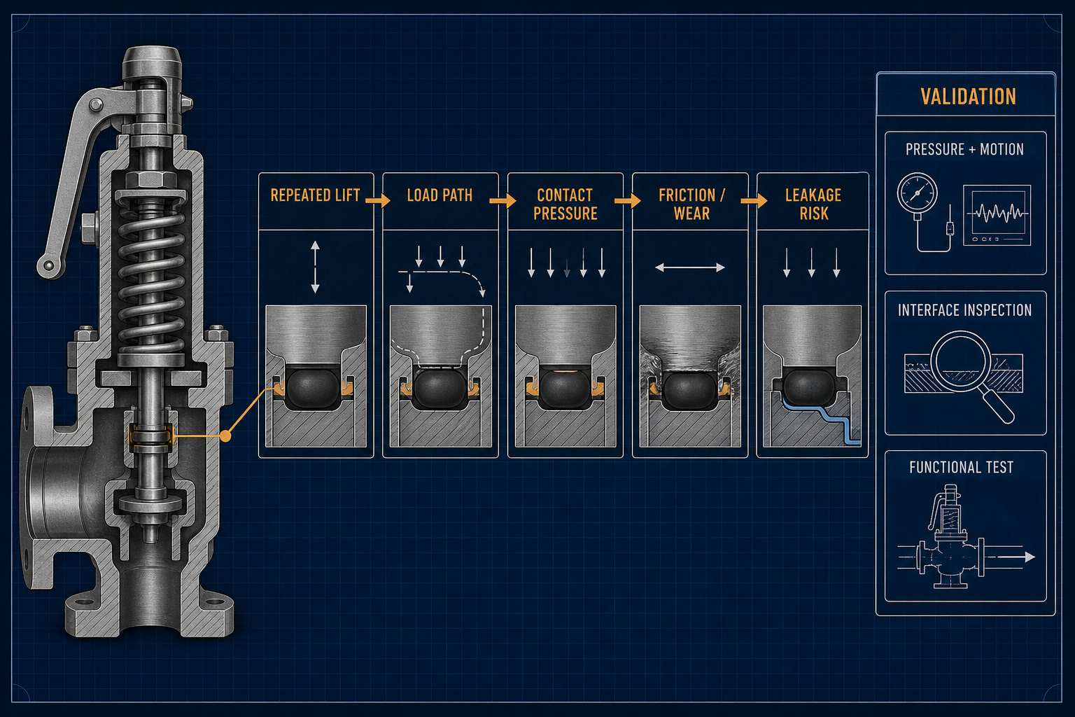
The chain is: repeated lift changes the load path; the path can redistribute O-ring deformation and contact pressure; changing contact can alter friction, sliding, rolling, extrusion or surface interaction; repeated interaction may contribute to wear or material change; and these conditions may accompany leakage or unstable function. Pressure records alone cannot prove contact load. Dynamic records, inspection, defined leakage or functional tests and repeatability evidence are required.
Safety-Valve and O-Ring Interface Architecture
The relevant object is the assembled interface, not an isolated O-ring or nominal groove drawing. A pressure-protection device may contain a moving closure member, stem, piston, guide, sleeve, cover, auxiliary chamber or pilot-related boundary. An O-ring may be located at one of these interfaces, but its position and role are not specified here. It must not be assumed to be the primary seat seal or to carry the same load as the pressure boundary.
Review the moving component, pressure zones, guide, support, groove, extrusion gap, surface, assembly direction and intended motion. Establish whether the O-ring is static, reciprocating, intermittent or supporting. These distinctions control the relationship between pressure, displacement, friction and contact pressure.
A seal compressed at rest may unload locally when a component shifts, tilts or moves. A clearance acceptable under one pressure direction may become an extrusion path when pressure reverses or alignment changes. Swelling, compression set, wear, contamination or thermal exposure may also change operating contact.
Table 1 – Safety-Valve and O-Ring Features That Influence Load Transfer
| Structural Feature | Possible Load-Transfer Mechanism | O-Ring Contact Effect | Potential Risk | Recommended Check |
| O-ring location and function | Determines how motion reaches the seal | Contact may remain stable or redistribute | Incorrect failure attribution | Confirm cross-section and seal function |
| Guide and alignment | Controls lateral movement, tilt and symmetry | One-sided loading or unloading | Wear, leakage or unstable motion | Inspect guide, alignment and motion path |
| Clearance and extrusion gap | Allows deformation under pressure and movement | Local support may decrease | Extrusion, nibbling or cuts | Review actual groove and pressure-side geometry |
Repeated Lift Events and Load-Transfer Mechanisms
Normal opening and reseating are intended functions. Repeated lift becomes a concern when unexpected, unstable, associated with pressure fluctuation, leakage, damage or drift, or outside the defined condition. Define it from synchronized evidence, not one pressure trace or visual impression.
Separate four loads: external pressure on the pressure boundary; O-ring contact from deformation, geometry, pressure and support; friction from contact, motion, surface and medium or lubrication; and recovery, inertial or impact effects during movement and reseating. They can be related but are not interchangeable measurements.
During lift, pressure may change the force on the moving member and may alter O-ring deformation if the seal lies in that load path. Motion may produce sliding, rolling, twisting or lateral shift. On reseating, contact may recover incompletely or unevenly after friction, damage, material change, compression set or contamination. Without actual geometry and time-resolved measurements, these remain mechanisms to test.
Table 2 – Repeated-Lift Mechanisms and Evidence Requirements
| Suspected Mechanism | Observable Event or Signal | Possible O-Ring Response | Required Confirmation | Interpretation Boundary |
| Pressure-driven repeated lift | Opening and reseating correlate with pressure | Contact may vary with direction and position | Synchronized pressure and displacement | Correlation does not prove contact change |
| Guide-related lateral movement | Asymmetric motion or surface marking | One-sided contact or unloading | Guide, alignment and motion review | Marks do not identify the initiating cause |
| Contamination or debris | Particles, residue or sudden friction change | Interrupted or abrasive contact | Controlled particle and surface inspection | Distinguish contamination from seal wear |
Contact Pressure, Deformation and Friction Response
Initial compression creates a baseline contact condition, but operating contact is not defined by compression alone. Pressure can redistribute the local state. Motion can change the contact band, friction direction and sliding or rolling. Lateral shift or tilt can concentrate load on one side while reducing contact on another. The result may be stable sealing, transiently weakened contact, high friction or a local extrusion pathway, depending on the interface.
Average and local behavior must be separated. Adequate average compression can coexist with local unloading, excessive contact or movement toward a clearance. Repeated events can polish, score or contaminate a surface and change recovery.
Possible responses include sliding wear, rolling or twisting strain, pressure-reversal extrusion, particle interruption, swelling, hardening, cracking or compression set. These depend on compound, geometry, medium, temperature and motion history. Inspection cannot reconstruct full load history; contact-pressure claims require structural evidence, operating records, suitable analysis or measurement and repeatable functional or leakage results.
Operating Variables and Leakage-Risk Pathways
Pressure, differential pressure, back pressure and pressure rate can influence force on a moving member, but do not automatically define O-ring force. Transfer depends on seal location, support geometry, clearance, guide condition and movement. Align pressure records with displacement, opening and reseating signals, drive response and the timing of leakage or functional change.
Temperature and medium properties can alter viscosity, friction, swelling, hardening, recovery and adhesion. Particles, crystallization, contamination, lubrication and alignment can change the interface independently of lift. Record these as possible contributors, not causes without evidence.
Distinguish transient movement leakage, leakage after reseating, persistent external leakage, internal bypass and unstable function. Repeated lift may be associated with a leakage pathway, but association is not causation. Ask whether leakage follows the event, persists after stable reseating, corresponds to seal damage and can be reproduced under controlled cycles.
Table 3 – Operating Variables and O-Ring Load Response
| Operating Variable | Possible Influence on Lift or Load | Possible Contact / Material Response | Risk Indicator | Verification Method |
| Pressure and differential pressure | Changes pressure-side loading | Contact redistribution or extrusion tendency | Event-linked leakage or motion drift | Synchronized pressure and displacement |
| Back pressure and system interaction | May affect reseating force and balance | Incomplete recovery or changed contact direction | Unstable reseating or bypass | Record relevant upstream and downstream state |
| Temperature and medium | Changes viscosity, friction and material response | Swelling, hardening, softening or recovery drift | Progressive functional or leakage change | Condition record and seal assessment |
Characterization and Benchmark Testing
Start with the assembled interface. Record O-ring location and function, groove geometry, clearance, compression, guide condition, alignment, surface state, orientation and pressure boundaries. Compare intended and actual movement. If the seal is removed, record orientation and contact marks before handling changes the evidence.
Synchronize pressure, back pressure, displacement, opening and reseating events, drive response, force-related signals, temperature and leakage or functional outputs as applicable. The measurement system must distinguish actual lift from a pressure fluctuation that produces no relevant movement. Sensor position, sampling and time alignment matter because a boundary signal may not represent the seal interface.
Compare defined operating states rather than one event. Repeated cycles can show whether motion, friction response, leakage or contact evidence changes with event history. New, operated, post-maintenance or medium-exposed seals may be compared when supported by the test plan; no specific cycle count is assumed.
Inspect the O-ring, groove and mating surface for cuts, nibbling, extrusion, scoring, transfer, particles, cracking, swelling, hardening, compression set and recovery loss. Link observations to event records and geometry. One acceptable leakage result, one teardown or an undamaged appearance cannot establish complete dynamic validation.
Validation Path for Repeated-Lift O-Ring Load Changes
1. Architecture and Seal Geometry — Confirm valve structure, moving member, O-ring location and function, groove, clearance, compression, guide, alignment and surface state. This establishes the mechanical boundary, not dynamic load by itself.
2. Lift and Pressure Characterization — Synchronize pressure, back pressure, displacement, opening, reseating and repeated-event records. This identifies event relationships, not local O-ring contact pressure by itself.
3. Contact and Material Response — Combine contact or deformation assessment with teardown, surface evidence and material-state review. Appearance alone cannot reconstruct load history.
4. Leakage and Functional Evidence — Use a defined leakage, reseating, pressure-retention or functional method. A passing result represents the tested state, not every repeated-lift condition.
5. Repeatability and Change Control — Compare repeated cycles and reassess after seal, material, medium, pressure, temperature, alignment, maintenance or structural changes. Conclusions apply only to the represented configuration.
Engineering Controls and Maintenance Strategy
The first layer is structure and interface. Define O-ring function and motion; control groove geometry, compression, clearance, guide, alignment and surface transitions; and reduce unsupported deformation or extrusion paths. Inspect the assembled and operated interface.
The second layer is material and medium compatibility. Evaluate the actual compound, medium, temperature, pressure, lubrication and motion history together. Review swelling, hardening, softening, compression set, cracking, wear and recovery. A material name or compatibility statement alone does not prove dynamic sealing stability.
The third layer is operation, monitoring and maintenance. Record pressure, back pressure, lift and reseating behavior, repeated-event occurrence, leakage or functional drift and relevant conditions. Define inspection, replacement, assembly and post-maintenance verification from evidence, not a universal interval. Control particles, lubricant, burrs and misalignment introduced during service.
Do not change a seal to mask unexplained repeated lift without investigating the load path. Do not attribute every event to the mechanism when teardown shows seal damage or contamination. The control record should link event, contact evidence, functional result and change history.
FMEA Risk Analysis
This qualitative FMEA does not assign an RPN. Risk depends on architecture, O-ring function, medium, pressure, temperature, motion, guide condition, material state, leakage consequence and maintenance history. The rows are conditional mechanisms for investigation, not confirmed customer failures.
Table 4 – FMEA for Repeated-Lift O-Ring Load and Leakage Risk
| Failure Mode | Cause | Local Effect | System Effect | Detection Method | Control Action |
| Contact redistribution during repeated lift | Pressure and motion change the load path | Uneven contact or local unloading | Possible leakage | Synchronize motion, pressure, teardown and leakage | Review interface geometry and operating state |
| Local overload or extrusion | Clearance, pressure direction, alignment or support change | Nibbling, extrusion or edge damage | Reduced sealing margin | Groove and seal inspection | Control clearance, alignment, support and fit |
| Motion-related friction and wear | Repeated movement, contamination or poor surface | Scoring, transfer, particles or friction drift | Changed movement or leakage risk | Motion response and surface inspection | Control surface, contamination, lubrication and path |
| Loss of recovery | Compression set, ageing, exposure or material change | Reduced return contact | Leakage after reseating | Compare operated and reference seal | Confirm condition limits and replacement evidence |
| Swelling, hardening or cracking | Medium, temperature, chemistry or ageing | Changed dimensions or integrity | Movement restriction or leakage | Material review and teardown | Evaluate actual compound and exposure |
| Debris at interface | Wear, maintenance debris, corrosion or contamination | Interrupted or abrasive contact | Leakage or unstable reseating | Particle, residue and surface inspection | Control cleanliness and maintenance release |
| Load change misattributed | Pressure used without motion or contact evidence | Incorrect hypothesis | Missed cause or unnecessary replacement | Review synchronized event and interface data | Require causal correlation and evidence limits |
| Post-maintenance contact change | Damage, misassembly, alignment shift or altered fit | Changed contact or friction | Leakage or altered reseating | Installation record, teardown and functional test | Controlled assembly and release verification |
Conclusion
Repeated lift can expose an O-ring interface to changing pressure, motion, contact, friction and material conditions, but repeated lift alone does not establish O-ring failure. Conclusions must use the actual seal location and function, groove and guide geometry, medium and operating conditions, synchronized event records, interface evidence and defined leakage or functional results. Effective control combines interface design, material and medium assessment, monitoring, maintenance, repeat-cycle evaluation and change control. Pressure data, visual inspection or one passing test supports only the evidence boundary it actually covers.
FAQ: Safety-Valve O-Ring Load Changes During Repeated Lift
These questions address diagnosis, validation and maintenance when a safety valve shows repeated lift or changing sealing behavior. Conclusions depend on the actual architecture, O-ring function, conditions, measurements and interface evidence.
Q:What does repeated lift mean in a safety valve?
A:It means that the defined moving member opens or moves and returns repeatedly or intermittently. The application must define the event; it should not automatically be labelled chatter, resonance or another phenomenon.
Q:How can repeated lifting change O-ring load?
A:Pressure and movement can change the assembled load path. Depending on location, support, clearance and motion, the seal may experience contact redistribution, sliding, rolling, twisting, local unloading or local overload. These are mechanisms to verify, not universal outcomes.
Q:Is pressure load the same as O-ring contact load?
A:No. Pressure load acts on a pressure boundary, while contact load depends on seal deformation, geometry, support, pressure and relative movement. Pressure records show correlation, not necessarily local contact load.
Q:Can repeated lift events cause O-ring wear or leakage?
A:They can contribute when movement produces sliding, abrasion, extrusion, contamination, recovery loss or another interface change. Causation requires event records, seal and surface evidence and a defined leakage or functional result.
Q:How should opening and reseating events be recorded?
A:Use synchronized pressure, back-pressure, displacement, opening, reseating, force-related, temperature and leakage or functional records as appropriate. Document measurement location, time alignment and event definition.
Q:How can repeated-lift damage be distinguished from O-ring ageing?
A:Compare event history with teardown evidence and reference states. Localized scoring, cuts, extrusion or transfer may follow motion, while swelling, hardening, cracking or compression set may indicate broader ageing. Mechanisms can coexist.
Q:What evidence is needed to validate O-ring load stability?
A:Combine geometry review, synchronized lift and pressure characterization, contact or deformation assessment, seal and surface inspection, defined leakage or functional evidence, repeated-cycle testing and change control. No single signal proves complete load stability.
Q:When should a safety-valve O-ring be inspected, replaced or revalidated?
A:Consider reassessment after leakage, unstable reseating, changed motion, unexplained repeated lift, damage, altered material condition, contamination, maintenance or changes in medium, pressure, temperature, alignment or structure. A universal interval requires application-specific evidence.
Post time: Sep-22-2026