
Blockage-Induced Seal Heating as a Local Reliability Problem
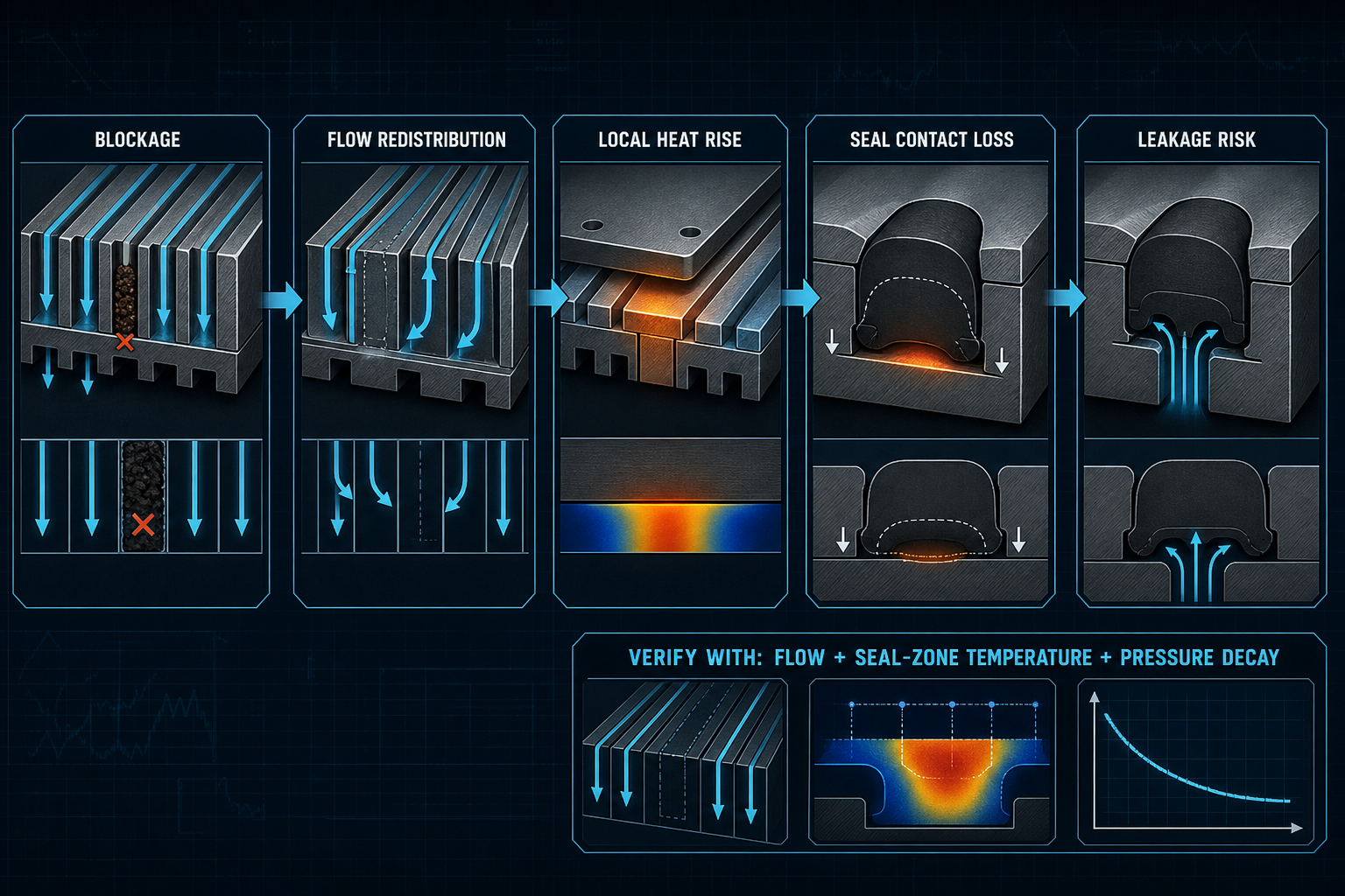
Microchannel blockage in a cold plate is not a uniform thermal event. It changes local flow, local pressure distribution and convective heat transfer, so the seal groove, cover edge, end cap or interface boundary can heat while the average cold-plate temperature still looks acceptable. The seal does not respond to the average value; it responds to the temperature history at its own compressed contact zone.
The engineering problem is therefore local and coupled. Blockage location, flow redistribution, thermal resistance, cover-plate stiffness, bolt preload, seal squeeze, material response and leakage evidence must be interpreted together. A pressure-drop trend, infrared image or single peak temperature can indicate abnormal behavior, but none of them alone proves that the seal has overheated or failed. The mechanism is confirmed only when flow, thermal and seal evidence converge.
Flow Redistribution After Partial or Complete Microchannel Blockage
Blockage can originate from particles, precipitates, corrosion products, coolant degradation debris or manufacturing residue. Once a microchannel loses effective area, the local hydraulic resistance rises. Some coolant may accelerate through the remaining open area, some may shift into adjacent parallel channels, and some regions can become low-velocity pockets. The blocked passage may also generate local recirculation or backflow depending on inlet layout and downstream resistance.
Partial blockage and near-complete blockage are not the same condition. Partial blockage can preserve a misleading total flow rate while starving the downstream heat-transfer area. Near-complete blockage can force heat laterally through the substrate toward neighboring channels, cover edges or sealing boundaries. A higher pressure drop proves that the hydraulic network changed, but it does not by itself locate the thermal peak or identify the seal exposure zone. Conversely, a visible local hot spot does not prove that the seal is already leaking. The seal may still be holding pressure while compression set, softening or contact-pressure redistribution is accumulating. That distinction matters because the corrective action for a hydraulic obstruction, a cover-contact problem and a damaged seal is different.
The position of the blockage matters. An upstream obstruction may alter the flow split before the heat source. A downstream obstruction may raise pressure and reduce heat removal after the heat has already entered the cold plate. A blockage near a seal groove or end-cap interface can create a boundary-zone temperature field that differs from the core channel field. Flow evidence and thermal evidence must be separated before they are recombined.
Heat-Transfer Path from Blocked Channel to Seal Groove
When local velocity decreases, convective heat transfer weakens. The thermal boundary layer thickens, the local heat-transfer coefficient falls, and heat flux seeks alternative paths through the cold-plate base, cover plate and bolted interface. The highest surface temperature may not sit directly above the blockage because lateral conduction, material thickness and contact thermal resistance shift the thermal peak.
Seal grooves are often placed near cover edges, end caps, manifolds or interface boundaries, not at the center of the most uniform thermal region. These locations can be sensitive to local heat spreading. A cover plate with poor contact, uneven bolt preload or a local air gap can add contact thermal resistance, raising the temperature near a seal even when channel-wall temperature appears lower elsewhere.
Transient and steady-state responses must also be distinguished. A startup blockage event may produce a short spike before the system redistributes flow. A gradual accumulation of debris may produce a slow thermal drift. A recurring particle migration event may create repeated thermal cycling at the seal. Each pattern has a different effect on elastomer recovery, compression set and leakage risk.
Table 1 – Heat-Transfer Signals After Microchannel Blockage
| Observed Signal | Possible Mechanism | Expected Location | Required Confirmation | Interpretation Limitation |
| Local hot spot | Reduced convection | Near blocked channel | Flow and temperature map | May be contact resistance |
| Downstream rise | Starved flow | After blockage | Channel flow check | Not always seal-related |
| Shifted thermal peak | Lateral conduction | Offset from blockage | Substrate sensors | IR may miss depth |
| Seal-groove rise | Boundary heating | Gland or cover edge | Embedded sensor | Surface data may mislead |
| Transient spike | Flow instability | Start-up or cycling | Time response data | Not steady-state risk |
| Edge heating | Cover contact loss | End cap or interface | Flatness and preload audit | May not be blockage-only |
Seal Compression and Contact Pressure Under Local Heating
Local heating changes the seal system through both material behavior and mechanical constraint. Elastomer hardness may drop during hot exposure and rise after thermal aging. Modulus, rebound and compression set can drift. Thermal expansion can raise squeeze in one region while cover-plate distortion or bolt-preload relaxation lowers contact pressure somewhere else. The result is often contact-pressure redistribution rather than a simple global loss of compression.
A short spike, repeated cycling and sustained heating have different consequences. Short exposure may mainly alter friction or temporary stiffness. Thermal cycling can grow compression set and make leakage appear after restart. Sustained local heating can accelerate embrittlement, extrusion, stress relaxation or loss of conformability. The primary flow-boundary seal, interface seal and end-cap seal may each see a different temperature-time profile.
The gland geometry determines whether temperature becomes a failure driver. High gland fill can leave little room for thermal expansion, increasing extrusion risk when the seal softens. Low squeeze can become a leakage path when shrinkage or cover distortion reduces contact pressure. An extrusion gap that is harmless at baseline may become critical when the material softens and pressure remains present.
Table 2 – Local Heating and Seal-Performance Consequences
| Thermal Change | Seal-Level Effect | Possible Failure Mode | Detection Method | Engineering Concern |
| Short spike | Temporary softening | Momentary seepage | Fast sensor and leak check | Peak alone is insufficient |
| Sustained heating | Set growth | Contact-pressure loss | Compression-set test | Long exposure dominates |
| Thermal cycling | Recovery loss | Leak after restart | Cycle plus pressure decay | Single hold may pass |
| Gland gradient | Uneven squeeze | Local extrusion | Section inspection | Average temperature hides risk |
| Cover distortion | Preload redistribution | Interface leak | Flatness and bolt check | Mechanical cause may dominate |
| Softened material | Lower extrusion resistance | Edge nibbling | Microscopic inspection | Gap support may be needed |
Combined Thermal, Flow and Seal Verification Sequence
Verification should begin with a clean baseline: flow rate, pressure drop, coolant inlet temperature, coolant outlet temperature, inlet pressure, outlet pressure and heat-source condition. The blockage degree and location must then be controlled or at least documented. Heat-source power, heat-flux distribution, substrate temperature, cover temperature and seal-groove temperature should be recorded in the same run so the data can be correlated.
Thermocouples, RTDs, infrared thermography and fiber-optic sensors answer different questions. Contact sensors can disturb the interface or add their own thermal path. Infrared data depends on surface emissivity and line of sight. Embedded sensors can miss a nearby peak if the placement is wrong. Fiber-optic sensing can improve spatial resolution but must still be anchored to a defined seal-risk location.
After heating, the seal must be evaluated as a used component, not a fresh material specimen. Hardness, compression set, cross-section shape, surface polish, extrusion marks, pressure hold, pressure decay, liquid leakage and gas leakage should be linked to the measured temperature history. Cross-section analysis can reveal whether damage came from heating, pressure, extrusion, assembly cut or cover movement.
Table 3 – Recommended Verification Sequence for Blockage-Induced Seal Heating
| Test Stage | Main Measurement | Failure Question | Useful Output | Key Limitation |
| Baseline test | Flow and pressure drop | Is the plate normal | Reference curve | No blockage evidence |
| Blockage simulation | Location and severity | Where flow is lost | Controlled comparison | Repeatability matters |
| Thermal mapping | Local temperature | Where heat accumulates | Gradient field | Sensor placement risk |
| Seal-zone sensing | Groove temperature | Is seal exposed | Seal thermal history | May need embedded sensors |
| Thermal cycling | Repeated temperature history | Does recovery degrade | Cycle response | Long test time |
| Post-heating leak test | Pressure decay/leakage | Did sealing change | Functional result | May miss delayed set |
| Failure analysis | Section and surface | What mechanism remains | Material evidence | Disassembly can add damage |
Design Variables Controlling Seal-Zone Hot Spots
Local seal temperature is controlled by the cold-plate hydraulic design and by the seal layout. Microchannel hydraulic diameter, channel count, inlet layout, outlet layout and channel balance determine how strongly a blockage redistributes flow. Cold-plate material, base thickness, cover thickness and lateral conduction path determine how heat reaches a boundary after one channel loses heat-transfer capability.
Seal-groove distance from the nearest channel is a design variable, not only a packaging constraint. A groove placed close to a high heat-flux region or to a manifold transition may see a larger thermal gradient after blockage. Seal cross-section, squeeze, gland fill, extrusion gap, cover stiffness, bolt pattern and bolt preload then decide whether that gradient becomes a sealing problem.
Protection measures must be shared between fluid and seal engineering. Filtration and cleanliness reduce blockage probability. Flow-path redundancy reduces the severity of one blocked channel. Local temperature monitoring reduces diagnostic blindness. Seal material selection must consider local gradients, thermal cycling, mechanical constraint, coolant compatibility and extrusion resistance, not only a catalog temperature rating.
Failure Modes and Engineering Controls
Common failure modes include particle blockage, coolant precipitation, boundary overheating, seal-groove thermal gradient, compression-set growth, thermal over-compression, thermal under-compression, cover distortion, uneven bolt preload, sensor placement error and reuse of a thermally exposed seal. Average cold-plate temperature may remain within expectation while the seal zone is outside its validated thermal-mechanical condition.
Controls should combine filtration, coolant cleanliness management, flushing verification, pressure-drop monitoring, local temperature monitoring, blockage simulation, thermal cycling, seal replacement rules, cover flatness control, preload control and spatial separation between the seal groove and high-risk flow boundaries. Flow data and temperature data must be interpreted together; separating them can hide the reason a seal changed. A useful control plan also records whether leakage begins during heating, after cool-down, after pressure cycling or only after disassembly, because those timings point to different root causes.
Maintenance decisions also matter. Removing a blockage does not erase prior thermal exposure. A seal may keep compression set, surface hardening, extrusion marks or loss of rebound after the channel is cleaned. The maintenance record should identify whether the seal remained compressed during the event, whether the plate cooled under pressure, and whether the joint was opened before leakage testing. If the seal was exposed to unverified local heating, reuse should require evidence from inspection and leakage testing rather than appearance alone.
FMEA Risk Analysis
The FMEA links hydraulic disturbance, local heating, seal mechanics and verification gaps. Risk ranking is application-specific and depends on cold-plate structure, seal material, coolant, pressure, operating temperature and consequence of leakage. No universal numerical RPN is assigned.
Table 4 – FMEA for Local Seal Temperature Rise After Cold-Plate Microchannel Blockage
| Failure Mode | Cause | Local Effect | System Effect | Detection Method | Control Action |
| Partial blockage | Particles or residue | Reduced local flow | Seal-zone heating | Flow and thermal map | Filtration and flushing |
| Near-complete blockage | Accumulated debris | Stagnant region | Hot spot and pressure drift | Pressure drop plus sensors | Cleanliness control |
| Coolant precipitation | Chemistry or temperature | Progressive restriction | Thermal instability | Fluid analysis | Coolant compatibility check |
| Flow redistribution | Parallel imbalance | Boundary overheating | Local seal aging | Channel balance test | Improve manifold layout |
| Seal temperature rise | Low convection | Material softening | Leakage or extrusion | Groove sensor | Move groove or add margin |
| Compression-set growth | Thermal exposure | Recovery loss | Leak after cycling | Set and pressure decay | Replacement rule |
| Cover distortion | Thermal gradient/preload | Uneven contact | Interface leak | Flatness and bolt audit | Preload control |
| Sensor placement error | Wrong measurement zone | Hot spot missed | False pass | Sensor correlation | Add seal-zone sensing |
| Seal reused after heating | Maintenance decision | Hidden aging | Delayed leak | Post-service leak test | Do not reuse without evidence |
Conclusion
Microchannel blockage is not only a flow-loss problem or an average-temperature problem. It can couple local heat flux, flow redistribution, temperature gradient, cover mechanics, bolt preload and seal contact pressure. Reliable validation must identify blockage location and severity, measure flow and pressure drop, map seal-zone temperature, evaluate thermal cycling, inspect material change, and confirm leakage or pressure-decay behavior before reuse or design approval. The seal must be judged at its local compressed interface, not at the cold plate average. That judgment should include both the thermal route that created the exposure and the mechanical route that changed contact pressure.
FAQ
Q:Can a microchannel blockage raise the temperature of a nearby seal?
A:Yes. If blockage reduces local flow or redirects heat toward a boundary, the seal groove or cover-plate interface may heat more than the average cold plate. The effect depends on blockage location, heat-source position, substrate conduction, cover contact and groove distance. Confirmation requires local seal-zone temperature data, not only inlet and outlet coolant data. It also requires evidence that the temperature event overlaps the seal location and exposure time.
Q:Why can the local seal temperature rise even when the average cold-plate temperature looks acceptable?
A:Average temperature hides spatial gradients. A blocked channel can create a local hot spot while other channels continue cooling enough to keep the mean value acceptable. Heat may spread laterally into a cover edge, manifold transition or seal groove. Use local sensing and flow-distribution evidence before judging seal exposure. The mean temperature can remain stable because unaffected channels continue removing heat.
Q:Does a higher pressure drop always prove that the seal area is overheating?
A:No. Higher pressure drop can indicate restriction, but it does not locate the thermal peak or prove seal heating. The blockage may be far from the seal, or bypass flow may protect the groove. Pair pressure with local temperature, flow distribution and seal-zone sensing before assigning the mechanism.
Q:Which seal properties are sensitive to local thermal exposure?
A:Compression set, modulus, rebound, hardness, friction and extrusion resistance are sensitive. The critical property depends on material, squeeze, gland fill, pressure and exposure duration. A short spike may change friction temporarily, while repeated or sustained heating can reduce recovery and contact pressure after cycling.
Q:How should local seal temperature be measured inside a cold-plate assembly?
A:Use a combination of methods where possible: embedded thermocouples or RTDs near the groove, surface thermal mapping, and correlation with coolant conditions. Sensor placement, response time, contact thermal resistance and emissivity must be controlled. A surface infrared image may not represent the internal seal temperature.
Q:Can thermal cycling after blockage cause leakage even after the blockage is removed?
A:Yes. The blockage may be cleared while the seal retains compression set, thermal aging, distortion or surface damage. Cover-plate distortion and bolt-preload changes can also remain. Post-cleaning validation should include pressure decay, leakage checks, seal inspection and, when relevant, replacement rather than assuming recovery.
Q:Should a seal be reused after a cold plate has experienced local overheating?
A:Reuse should be evidence-based. If the seal saw unverified local heating, compression set, hardness, dimensions and surface condition may have changed. A normal visual appearance is not enough. Reuse requires inspection and leakage or pressure-decay testing under relevant pressure and temperature conditions. If the event history is unknown, replacement is usually easier to justify than assuming recovery.
Post time: Sep-10-2026