
Executive Summary
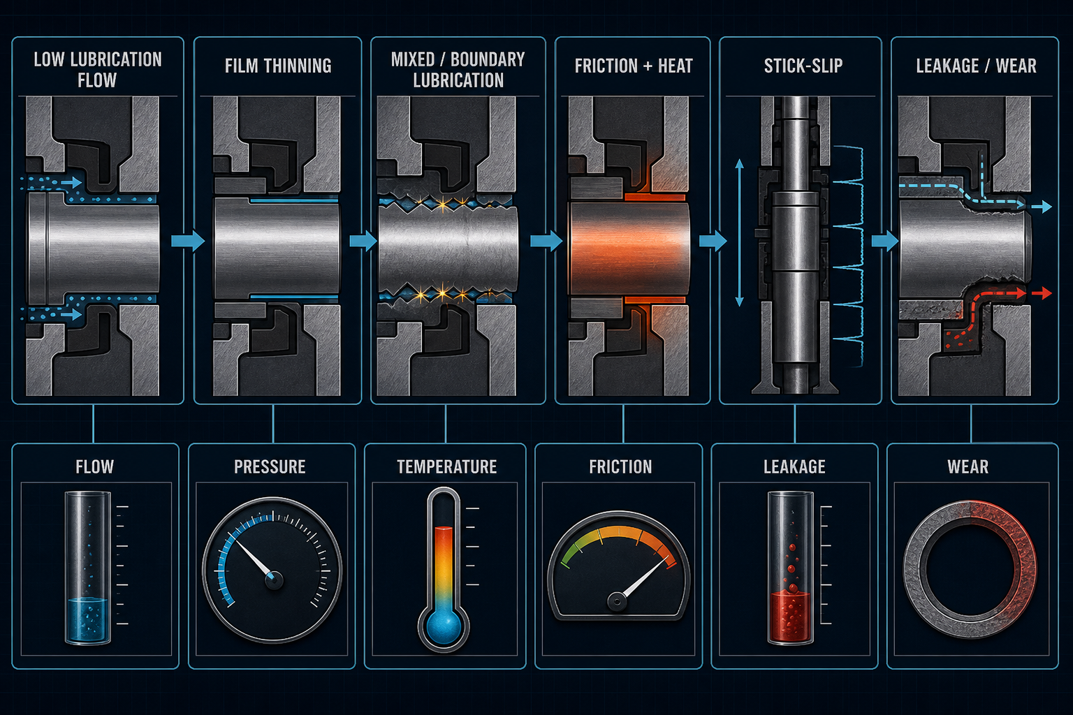
A metering-pump plunger seal operates under reciprocating sliding, cyclic pressure and repeated start-stop conditions. Its behavior depends not only on seal material and preload, but also on whether lubricant or flush fluid can continuously replenish the local contact. When supply flow is reduced, intermittent or uneven, film thickness may fall and the interface may move from hydrodynamic or elastohydrodynamic lubrication toward mixed or boundary lubrication.
That transition can change friction force, breakaway force, frictional heating and plunger-motion stability. The result may be stick-slip, temperature rise, transfer-film change, wear debris, seal weeping or variable plunger leakage. In longer service, a short-term flow disturbance may accumulate as seal wear, surface damage, altered preload or life variation. Process-fluid dilution, flush-fluid contamination and chemical attack can further change viscosity and surface condition.
Low-flow lubrication instability is therefore not simply a flow-system problem. It is a coupled condition involving bulk flow, local interface replenishment, pressure differential, reciprocating speed, seal compression, lubricant viscosity, temperature, plunger surface condition and process-fluid compatibility. A defensible diagnosis must connect flow, pressure, temperature, friction, leakage, wear and cycle history. Inlet flow alone cannot prove that stable lubrication exists at the seal interface.
Metering-Pump Plunger Seal Architecture and Lubrication Path
A plunger metering pump, also called a dosing pump or reciprocating metering pump, may use a plunger, seal housing, plunger seal, plunger packing, reciprocating seal, wiper seal, guide ring, seal gland, flush chamber, lubrication chamber, barrier or buffer fluid, drain path and recovery path. The seal stack separates the process-fluid side from the atmospheric side while accommodating reciprocating stroke, pressure variation and dimensional change. The local contact is governed by preload, gland compression, plunger motion, surface roughness and the pressure gradient across the seal.
Lubrication may be supplied as external flush, barrier fluid, lubrication oil, process-fluid lubrication, water-based lubrication, chemical-compatible flush or controlled leakage lubrication. These terms describe circuit functions, not necessarily the fluid volume entering the actual contact. Bulk lubrication flow can be restricted by seal lips, packing resistance, clogged passages, pressure direction, viscosity and drainage. Plunger entrainment may replenish one region while leaving another locally starved.
The diagnostic distinction is between bulk lubrication flow, local seal-interface replenishment, leakage flow, flush flow, drainage flow and recirculation flow. Temperature changes viscosity; speed changes entrainment; preload changes contact pressure; and surface roughness changes the ability of a film to separate asperities. A measured inlet flow is therefore a boundary condition, not direct evidence of interface film stability.
Table 1. Lubrication-Path Variables in Metering-Pump Plunger Seals
| Lubrication Variable | Local Interface Effect | Possible Instability | Seal-Level Consequence | Recommended Confirmation |
| Bulk lubrication flow | Sets available supply | Local starvation despite flow | Variable friction | Measure inlet and return |
| Local replenishment | Restores film | Delayed refill | Film thinning | Tracer or local balance |
| Flush flow | Dilutes or cools interface | Uneven distribution | Changed viscosity | Flow-path inspection |
| Leakage flow | Carries fluid through seal | Excessive weeping | Loss of lubricant | Collect and classify |
| Drainage flow | Removes fluid and heat | Blocked recovery | Fluid accumulation | Drain-pressure check |
| Recirculation flow | Controls fluid condition | Contamination buildup | Debris or viscosity shift | Fluid analysis |
| Pressure differential | Drives fluid movement | Fluid expelled from contact | Starvation or extrusion | Record both pressures |
| Plunger entrainment | Carries fluid into contact | Low-speed loss of film | Start-stop instability | Speed and friction trace |
Lubrication Regimes and Low-Flow Instability Mechanisms
Hydrodynamic lubrication separates surfaces through a pressure-generating fluid film created by relative motion. Elastohydrodynamic lubrication adds elastic deformation and pressure-dependent viscosity effects. In a seal, these regimes are local and transient rather than uniform across the packing set. At lower speed, higher contact pressure, greater roughness or lower viscosity, asperity interaction increases and the interface enters mixed lubrication. Boundary lubrication becomes dominant when the fluid film no longer carries much of the load and surface chemistry, transfer films or solid additives carry the contact.
A low-flow condition can reduce film thickness without producing complete loss of lubrication. If replenishment is slower than interface consumption or drainage, the film becomes discontinuous. The plunger may carry fluid out of the contact zone, while pressure differential expels fluid or prevents entry. Seal lips and packing elements can act as local flow restrictions. At low speed or stroke reversal, entrainment decreases; during start-up, the film may not yet be established. Intermittent operation can also allow evaporation, deposition or drying.
The same average flow can produce different states. Low average flow is different from intermittent flow, pulsating flow, uneven distribution, delayed replenishment, local starvation and complete loss of lubrication. Process-fluid dilution can lower viscosity or change boundary chemistry. Temperature rise can reduce viscosity further, creating a feedback toward film collapse. Squeeze-film effects during compression and reversal may temporarily support load, but they do not prove steady replenishment.
Table 2. Lubrication-Regime Changes Under Low-Flow Conditions
| Lubrication Regime | Dominant Mechanism | Friction Behavior | Seal Risk | Required Evidence |
| Hydrodynamic | Motion-generated film | Low and stable | Low asperity contact | Speed, viscosity and friction |
| Elastohydrodynamic | Film plus elastic deformation | Load-sensitive | Local heating if film thins | Pressure and temperature |
| Mixed lubrication | Film plus asperity contact | Variable or hysteretic | Wear and transfer film | Friction trace and microscopy |
| Boundary lubrication | Surface chemistry carries load | Higher running friction | Wear, debris and heat | Surface and fluid analysis |
| Intermittent replenishment | Delayed local refill | Cycle-dependent | Start-stop instability | Time-resolved flow |
| Local starvation | Consumption exceeds refill | Abrupt friction rise | Stick-slip and wear | Local balance and temperature |
| Complete loss of lubrication | No effective separating film | Severe friction increase | Rapid damage or seizure risk | Flow, friction and inspection |
Friction, Heat Generation and Plunger-Motion Instability
When film support decreases, breakaway friction and running friction can rise. Friction hysteresis may appear between forward and reverse strokes, and stick-slip can make plunger speed fluctuate even when the drive command is constant. The pump may then show stroke-to-stroke variation, position error, dosing irregularity or increased drive load. A seal can also respond mechanically: higher contact pressure raises friction, seal extrusion can alter the contact land, while wear may later reduce contact pressure and increase leakage.
Frictional heating is both a consequence and a driver. Heat accumulates in the seal housing, plunger and lubricant. Local flash temperature at microscopic contacts can be much higher than average housing temperature. Thermal expansion can reduce clearance or increase contact pressure; thermal softening, hardening or transfer-film formation can change friction. As lubricant temperature rises, viscosity may fall and film thickness may decrease further. Debris then acts as a third body, accelerating wear and surface damage.
A useful instability loop is: lubrication flow reduction, friction increase, frictional heating, viscosity reduction, film thinning, then further friction and wear. This loop must be tested rather than assumed. Average housing temperature, local seal temperature, plunger surface temperature, lubricant temperature and transient flash temperature are different observations and should not be substituted for one another.
Table 3. Low-Flow Lubrication Signals and Plunger-Seal Consequences
| Observed Signal | Possible Mechanism | Seal-Level Effect | Pump-Level Consequence | Verification Method |
| Higher breakaway force | Boundary contact at start | Adhesion or local wear | Start-up delay | Force trace |
| Friction hysteresis | Different forward and reverse films | Uneven contact | Stroke variation | Bidirectional friction test |
| Stick-slip | Frictional instability | Surface transfer or debris | Plunger speed fluctuation | Position and force trace |
| Housing temperature rise | Accumulated friction heat | Softening or hardening | Thermal drift | Temperature mapping |
| Local hot spot | Flash temperature or poor heat removal | Accelerated wear | Shortened stable run | Thermal imaging |
| Variable leakage | Wear, extrusion or pressure effect | Weeping or loss of seal | Dose and fluid-balance drift | Leak collection |
| Transfer film change | Surface chemistry or material transfer | Changed friction coefficient | Cycle-dependent load | Microscopy and fluid analysis |
| Debris generation | Third-body wear | Abrasive contact | Progressive degradation | Mass and morphology check |
Seal Material, Geometry and Process-Fluid Compatibility
Relevant designs may use PTFE-based packing, filled PTFE, graphite-filled polymer seals, PEEK or polymer backup elements, FKM/FPM, EPDM, NBR or HNBR, polyurethane, silicone, composite packing systems, braided packing or formed packing. No material is universally suitable. Friction, thermal conductivity, compression recovery, wear resistance, chemical response and heat stability must be considered under the actual plunger motion and pressure differential.
A low-friction material does not automatically produce the lowest wear under low-flow conditions. Filled PTFE may change its transfer film; graphite or other solid lubricants may modify friction and heat conduction but are not a substitute for stable liquid replenishment. Elastomers may absorb process fluid, swell, harden or develop compression set, changing contact pressure. The surface state may matter more than the material name: roughness, glaze, contamination and prior thermal history alter friction behavior.
The process fluid can dilute, contaminate or remove lubricant. A flush fluid mixed with process fluid can change viscosity, chemical compatibility and seal life. Plunger roughness, hardness, coating and corrosion affect counterface wear. Seal cross-section, packing-stack length, compression, gland geometry and extrusion clearance determine local lubrication demand. Material selection should therefore include low-flow friction stability, lubricant and process-fluid compatibility, debris generation, heat dissipation, leakage tolerance, cleanability and maintenance repeatability.
Characterization and Benchmark Testing
A credible test starts with a lubrication-flow baseline and calibrated flow meter. Record inlet and return flow, lubricant pressure, differential pressure, lubricant temperature, process-fluid temperature, plunger speed, stroke length, stroke frequency, start-stop sequence, reversal behavior and seal preload or gland compression. Inspect plunger runout, alignment, surface roughness, coating condition and seal geometry before interpreting friction or leakage.
Measure breakaway force, running friction, friction hysteresis, housing temperature and local seal temperature where practical. Local thermal imaging or embedded sensing may reveal a hot spot hidden by average housing temperature. Measure controlled leakage separately from uncontrolled leakage, and use pressure-decay testing when a pressure boundary must be evaluated. Collect wear debris, inspect the surface by microscopy, examine transfer film or glaze, and compare lubricant viscosity and contamination before and after testing.
The validation path should include long-duration endurance, low-flow step-change, flow recovery, repeated start-stop, different plunger speeds, and controlled pressure and temperature conditions. The critical distinction is between flow supplied to the lubrication circuit, flow entering the seal contact, flow leaving the housing, controlled leakage and recovered fluid. A single static flow reading cannot prove stable interface lubrication, and a single leakage reading cannot establish long-term seal life.
Engineering Controls and Maintenance Strategy
Establish a validated lubrication-flow window rather than adopting one universal flow value. Control lubricant pressure, differential pressure, temperature and viscosity. Design local replenishment paths without dead zones or blocked passages, and monitor inlet and return flow separately. Use suitable filtration and contamination controls, and prevent process-fluid dilution or flush-fluid cross-contamination.
Control plunger roughness, hardness, coating and runout. Optimize seal preload and gland compression while limiting extrusion clearance. Select materials for low-flow friction stability, lubricant compatibility and wear debris control. Use a controlled start-up and shutdown sequence that allows replenishment before full-speed operation. Monitor friction, temperature, leakage and wear trends, and define inspection and replacement criteria.
Maintenance records should include lubricant batch, temperature, viscosity, contamination history, seal replacement, housing alignment, plunger condition and start-stop history. Increasing lubricant flow cannot correct poor geometry, plunger eccentricity, rough surfaces, chemical incompatibility or excessive preload. The system must be verified after maintenance or seal replacement under the same defined endpoint and measurement method.
FMEA Risk Analysis
This FMEA uses no numerical RPN. Qualitative risk depends on seal design, plunger size and speed, pressure differential, lubricant properties, process-fluid chemistry, temperature, leakage tolerance, pump duty cycle and failure consequence.
Table 4. FMEA for Low-Flow Lubrication Instability in Metering-Pump Plunger Seals
| Failure Mode | Cause | Local Effect | System Effect | Detection Method | Control Action |
| Insufficient lubricant supply | Low source flow or restriction | Thin or missing film | Friction and wear rise | Flow and friction trace | Validate supply window |
| Intermittent or pulsating lubrication flow | Pump or regulator pulsation | Periodic refill loss | Cycle-dependent leakage | Time-resolved flow | Stabilize delivery |
| Local lubrication starvation | Poor interface replenishment | Asperity contact | Stick-slip and debris | Local temperature check | Improve flow path |
| Excessive differential pressure across the seal | Pressure imbalance | Lubricant expelled | Seal weeping or wear | Dual pressure record | Balance pressure |
| Lubricant viscosity reduction due to temperature rise | Frictional heating | Film thinning | Thermal instability | Viscosity and temperature | Control heat removal |
| Process-fluid dilution of the lubricant | Cross-mixing or intrusion | Changed boundary film | Chemical or wear drift | Fluid composition | Separate or condition fluids |
| Blocked lubrication passage | Residue, filter or valve blockage | No local refill | Progressive damage | Pressure and flow check | Clean and monitor passage |
| Seal preload too high | Gland over-compression | High contact pressure | Friction and heat rise | Compression inspection | Set preload window |
| Seal preload too low | Insufficient compression | Poor film retention or extrusion | Leakage increase | Leak and geometry check | Restore compression |
| Plunger runout or misalignment | Guide, shaft or assembly error | Uneven contact | Localized wear | Runout measurement | Correct alignment |
| Excessive plunger surface roughness | Damage or poor finish | Film disruption | Abrasive seal wear | Surface profilometry | Restore surface condition |
| Stick-slip and frictional heating | Boundary contact and adhesion | Thermal and surface damage | Motion variation | Force and temperature trace | Reduce instability source |
| Transfer-film instability | Material transfer or chemistry shift | Changing friction | Cycle-to-cycle behavior | Microscopy and fluid analysis | Control material and fluid |
| Seal wear and debris generation | Long exposure or starvation | Loss of sealing surface | Leakage and contamination | Mass, debris and leak test | Inspect or replace seal |
| Controlled leakage misidentified as abnormal leakage | No defined leakage baseline | Wrong diagnosis | Unnecessary intervention | Flow balance and history | Define leakage criteria |
| Seal failure caused by repeated low-flow start-stop cycles | Film absent during starts | Repeated local damage | Shortened seal life | Cycle test and force trace | Control start-up sequence |
Conclusion
Low-flow lubrication instability in a metering-pump plunger seal is not simply insufficient flow and not simply a material problem. It is a coupled response involving lubricant supply, local interface replenishment, pressure differential, viscosity, reciprocating speed, stroke reversal, seal compression, temperature, plunger surface condition and process-fluid compatibility.
Reliable judgment must connect flow supplied to the circuit with the actual interface state, friction and breakaway force, local seal temperature, controlled and uncontrolled leakage, transfer film, wear debris, long-term cycling and start-stop history. Stable lubrication cannot be confirmed by inlet flow alone. It requires evidence from flow, pressure, temperature, friction, leakage, wear and defined test conditions.
FAQ
Q:What is lubrication starvation in a metering-pump plunger seal?
A:Lubrication starvation is a condition in which local replenishment cannot sustain the film or boundary chemistry required by the seal contact. It may be local or intermittent rather than a complete absence of fluid. Confirmation requires interface-related evidence, not only a low bulk-flow reading.
Q:Can low lubrication flow increase plunger-seal leakage?
A:It can increase leakage when film loss, heat, wear, extrusion or altered contact pressure damages the sealing interface. Low flow alone does not prove that leakage will increase. Pressure differential, seal preload, material compatibility, plunger condition and leakage definition must be evaluated together.
Q:Why can friction rise even when some lubricant is still flowing?
A:Flow may bypass the loaded contact, arrive intermittently, be expelled by pressure, or have insufficient viscosity at temperature. A small bulk flow can therefore coexist with mixed or boundary lubrication at the interface. Time-resolved flow, friction and temperature data are needed to distinguish this mechanism.
Q:How does plunger speed affect lubrication-film stability?
A:Speed changes entrainment and the ability of the plunger to carry fluid into the contact. Very low speed, reversal and dwell can reduce film formation, while higher speed may increase heat and fluid shear. The relevant response depends on seal geometry, viscosity, load and pressure differential.
Q:Is higher lubricant flow always better for a plunger seal?
A:No. More flow may improve replenishment or cooling, but can also increase dilution, process-fluid transport, leakage, contamination or hydraulic loading. The appropriate value must be validated for the pump, seal, lubricant, pressure, temperature and leakage tolerance rather than assumed from a universal rule.
Q:How can controlled leakage be distinguished from abnormal seal failure?
Controlled leakage has a defined path, stable trend and acceptable fluid composition under specified conditions. Abnormal leakage usually shows a change in rate, pressure response, fluid balance, wear evidence or surface damage. The distinction requires a baseline, collection method, pressure record and inspection history.
Should a plunger seal be replaced after a low-flow overheating event?
Replacement depends on evidence of permanent damage. Inspect for hardening, softening, transfer film, cracking, extrusion, debris, altered friction and leakage after the event. If recovery testing does not restore the defined baseline, replacement is more defensible than relying on visual appearance alone.
Post time: Sep-18-2026