
Executive Summary
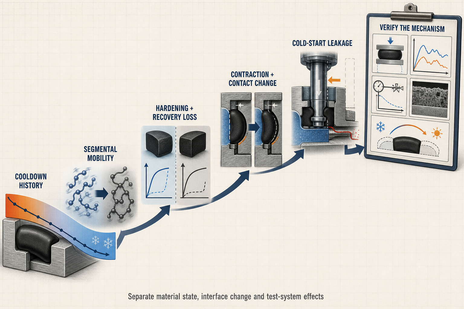
Low-temperature rubber sealing fails through coupled changes rather than one temperature threshold. Cooling reduces segmental molecular mobility, raises modulus and slows compression recovery before a visible leak. Near a glass-transition region, the response can depend strongly on temperature history and rate, leaving a seal intact but with less contact reserve and counterface conformity.
Cooldown also changes elastomer, housing, shaft, support and lubricant state. Squeeze, groove fill, clearance and contact width shift together. During cold start or motion, hardening, contraction, lubricant viscosity increase, frost and phase change can produce leakage or incomplete travel. Glass-transition temperature is not minimum operating temperature, and warm-up recovery or room-temperature pressure holding is not proof of reliability.
Low-Temperature Sealing Architecture and Leakage Boundaries
An O-ring, gasket, lip seal, U-cup, piston seal, rod seal, wiper or valve-stem packing isolates a low-temperature medium from a low-pressure or atmospheric side through a boundary formed by the housing, groove, shaft or rod, counterface, pressure direction and thermal path. Static joints rely on compression and recovery; dynamic joints must adapt while the shaft, rod or piston moves and while lubrication controls friction.
A static O-ring, cryogenic valve-stem seal, LNG gasket, hydrogen rod seal and battery thermal-management seal therefore have different deformation fields. Leakage may begin at a groove corner, extrusion gap, damaged counterface or locally uncompressed region even when the bulk elastomer has no obvious crack. Thermal gradients, frost or condensation can mimic a material leak, while gas temperature change can produce pressure decay without a new path.
Table I. Low-Temperature Rubber Sealing Zones and Functions
| Seal zone | Adjacent medium | Static or dynamic function | Main low-temperature risk | Leakage consequence | Verification focus |
| Compressed band | Liquid, gas or vacuum side | Static isolation | Hardening and recovery loss | Cold-start static leak | Compression and leak test |
| Dynamic lip | Shaft or rod interface | Sliding isolation | Friction and stick-slip | Dynamic leakage | Force, speed and leak record |
| Groove edge | Housing and clearance | Restraint and extrusion control | Differential contraction | Local bypass path | Clearance and edge inspection |
| Back side | Low-pressure or air side | Return and vent boundary | Frost or trapped condensate | False leak indication | Temperature and surface check |
| Counterface | Metal, plastic or coating | Motion and contact support | Roughness and contraction mismatch | Scuffing or crack initiation | Finish, runout and microscopy |
The same response can be benign in a supported static groove and critical in a moving interface.
Glass Transition, Segmental Mobility and Low-Temperature Hardening
Glass transition is a temperature region in which polymer segmental motion changes substantially. In the rubber-like state, chain segments can rearrange around microscopic surface irregularities and recover after compression. As temperature falls, that rearrangement becomes slower and less complete. The material may show higher modulus, higher hardness, changed damping and reduced recovery before it becomes visibly brittle. This is why “below the glass-transition temperature equals immediate failure” is an inadequate engineering rule.
The transition is controlled by polymer backbone, crosslink structure, fillers, additives, formulation, compression, cooling rate and measurement frequency. Physical aging can further reduce mobility. Dynamic-mechanical results describe a particular frequency and strain; they do not directly give compressed-seal contact pressure. Initial squeeze may preserve leakage resistance for a period after stiffness rises.
Failure analysis must separate temporary stiffness, persistent recovery loss and permanent damage. Warm-up may reduce temporary hardness, while set, cracking, wear, extrusion or irreversible dimensions may remain. A lower reported glass-transition temperature does not establish medium compatibility, friction, tear resistance or geometry suitability. Low-temperature hardness is diagnostic, not a complete acceptance criterion.
Thermal Contraction, Differential Contraction and Contact-Pressure Stability
Cooling changes the dimensions of the elastomer, housing, shaft, flange, backup ring and support elements. Differential thermal contraction can open a clearance gap, reduce squeeze, change groove fill or shift the contact band. Low-temperature retraction is therefore different from glass-transition hardening: retraction is a dimensional response, while hardening is a molecular-mobility and mechanical-response change. They may occur simultaneously, but they must be measured separately.
Pressure direction determines whether contraction improves or weakens containment. Excessive squeeze with low mobility can increase friction, extrusion and crack stress; insufficient squeeze with contraction mismatch can create a bypass path. A thermal gradient may leak one circumference or lip segment while the remainder remains seated.
Cross-section, compression, groove fill, pressure direction, edge radius, finish, runout, misalignment, stretch, twist and pinching define the contact margin. Backup support limits one extrusion path but cannot restore mobility or recovery. Fixed contraction, squeeze and clearance values are not universal standards.
Table II. Temperature, Glass Transition and Low-Temperature Leakage-Risk Matrix
| Operating factor | Primary effect | Secondary effect | Potential failure mode | Required measurement | Main limitation |
| Cooling toward transition region | Mobility reduction | Modulus increase | Hardening and recovery loss | Low-temperature force and recovery | Material and frequency dependent |
| Cooling rate | Thermal gradient | Uneven contact state | Local leakage | Temperature history | Does not define service life |
| Differential thermal contraction | Gap or squeeze change | Contact shift | Thermal-contraction leak | Component dimensions | Geometry specific |
| Cold-start motion | Friction and force increase | Stick-slip or travel loss | Dynamic leakage | Force, travel and speed | Needs representative motion |
| Frost or condensation | Surface interference | False pressure response | Temporary leak or jam | Surface and dew condition | Environment dependent |
| Thermal and pressure cycles | Repeated stress and recovery | Fatigue or extrusion | Delayed leakage | Cycle history and post-test check | No universal cycle limit |
This matrix is a mechanism map, not a pass-fail standard; interpret each drift with the tested material, compression, geometry, medium, pressure and thermal history.
Cold-Start Leakage and Dynamic Operation
Cold start asks the seal to contain pressure or move before mobility has recovered. A hardened seal resists deformation, viscous or partly solidified lubricant increases shear, and pressure can drive the seal toward a clearance gap. The first motion may require higher force, stick-slip or incomplete travel; a lip can lose its contact angle without an immediate external leak.
Static leakage may decrease during warm-up as contact recovers. Dynamic leakage may begin only during motion because friction, reversal, roughness and film conditions change the contact band. Frost, condensation and phase change can alter contact or pressure without elastomer damage. Repeated start-stop and thermal or pressure cycling can turn a temporary event into wear, extrusion or delayed leakage. Record force, travel, temperature, pressure, speed and leakage together.
Material Formulation, Geometry and Interface Control
NBR, HNBR, EPDM, FKM, FFKM, silicone rubber, fluorosilicone, polyurethane and PTFE-based elements can differ in flexibility, modulus drift, recovery, tear resistance, friction, wear, permeability and compatibility. Filled, plasticized, low-temperature and low-compression-set compounds involve trade-offs; a flexible compound is not automatically the best choice for tear, extraction, compression set or dynamic wear.
Selection must connect glass-transition behavior with the medium, pressure, temperature history, compression, clearance, motion, lubricant and counterface. Hardness cannot establish universal suitability. Burrs, cuts, twists, pinches, contamination, over-stretch, misalignment, excess clearance and excessive compression can create damage that resembles material failure.
Leakage Diagnosis and Low-Temperature Verification
A useful diagnosis separates static, dynamic, interface, permeation, contraction, recovery, extrusion, lubricant, frost and cracking failures. Pressure decay is not a mechanism by itself: gas temperature, test-volume expansion, phase change, sensor drift or test-system leakage can produce the same trend. A helium test can locate fine paths but does not prove dynamic movement.
Testing should progress from material response to representative component behavior. Low-temperature immersion, compression, compression recovery and retraction tests can identify trends, but they do not reproduce a groove, pressure direction, counterface or movement. Static leak, dynamic cycling, cold-start, thermal-cycle and pressure-cycle tests add those boundaries. Force, torque or thrust measurement is essential when movement is part of the sealing function.
Record sample, batch, temperature boundary, cooling rate, stabilization, pressure, medium, motion, speed, surface, lubricant, leakage method and warm-up. Dimensional inspection, hardness mapping, microscopy and cross-sectional analysis should distinguish temporary stiffness, recovery loss, set, extrusion, wear, aging or cracking. Preserve the seal before cleaning or warming it.
Warm-up recovery is a verification stage, not an eraser. A seal may regain mobility while retaining a crack, wear track, extrusion or set; warm-up pressure change may also come from gas temperature or phase change. Compare cold, warm and post-test physical evidence.
Table III. Low-Temperature Rubber-Seal Testing and Verification Guide
| Test or inspection | Test objective | Key variable | Detectable issue | Suitable stage | Main limitation |
| Low-temperature compression | Observe load response | Temperature and squeeze | Hardening or force rise | Material screening | Not a full seal test |
| Compression recovery | Assess return to contact | Time, temperature and strain | Recovery loss or set | Material and design review | Geometry may be absent |
| Cold-start leak test | Measure first-event containment | Cooldown, pressure and motion | Start leakage or travel loss | Component qualification | Setup sensitive |
| Dynamic cycling | Assess moving seal stability | Speed, stroke or rotation | Stick-slip, wear or leakage | Component qualification | Counterface dependent |
| Thermal and pressure cycles | Assess repeated exposure | Cycle sequence and dwell | Fatigue or delayed leak | Reliability verification | No universal duration |
| Warm-up and microscopy | Separate recovery and damage | Recovery history and morphology | Cracks, wear or set | Failure analysis | Handling can alter evidence |
Material results cannot be transferred directly to another geometry or operating mode. Strong evidence links molecular response, interface condition, measured leakage or motion and post-test morphology.
Maintenance, FMEA and Reliability Conclusion
Replacement records should verify material, batch, dimensions, storage, lubricant, groove, counterface, assembly, squeeze and clearance. After a cold-start leak or force increase, preserve the sample and record temperature, pressure, medium, motion and warm-up. Inspect for cuts, twists, contamination, abrasion, cracks and permanent change. One successful cold start does not prove reliability.
The RPN values are illustrative engineering risk rankings, not field statistics or experimental results. Recalculate them using the organization’s definitions. A single hardness shift, force result, leakage event or laboratory cycle is an observation for the tested configuration, not a universal lifetime or minimum temperature.
Table IV. Low-Temperature Rubber-Seal FMEA and RPN Analysis
| Failure mode | Cause | Local effect | System effect | Detection method | RPN | Corrective action |
| Transition hardening | Mobility reduction near transition | Conformity falls | Cold-start leak | Recovery and leak test | 240 | Qualify compound and geometry |
| Recovery loss | Thermal history, aging or set | Contact restoration slows | Delayed static leak | Recovery and warm-up check | 225 | Review compression and cycling |
| Differential contraction | Elastomer and housing mismatch | Squeeze or gap shifts | Thermal-cycle leak | Dimensions and interface check | 210 | Review clearance and support |
| Brittle cracking | Low mobility, notch or assembly damage | Surface or internal crack | Persistent leak | Microscopy and cross-section | 260 | Control edges and assembly |
| Excessive friction | Hardening, lubricant or finish | Force and stick-slip rise | Travel loss or wear | Force, torque and motion | 230 | Review lubricant and counterface |
| Frost interference | Condensation or phase change | Contact or motion blocked | Temporary leak or jam | Surface, dew and temperature | 170 | Control environment and repeat |
| Misdiagnosed pressure decay | Thermal, volume or sensor effect | False leak indication | Wrong corrective action | Blank and compensated test | 155 | Separate system effects |
| Inadequate verification | Ambient-only or single-event test | Hidden risk remains | Recurring field failure | Audit test matrix and records | 250 | Add cold-start and cycling |
Conclusion
Low-temperature rubber sealing is a coupled problem of molecular mobility, elastomer hardening, compression recovery, low-temperature retraction, thermal contraction and contact-pressure stability. Glass-transition behavior explains one material-state change but does not define the minimum operating temperature or predict leakage. Differential contraction, geometry, pressure direction, lubricant condition, frost, motion and surface state can dominate the result.
Reliable evaluation follows cooldown, molecular response, interface change, cold-start loading, leakage and warm-up recovery. Evidence must distinguish temporary stiffness from set, cracking, extrusion, aging, frost, permeation and test-system error through material screening, component tests, cycling and inspection.
Engineering FAQ
Q:What is the difference between glass transition and minimum operating temperature?
A:Glass transition describes mobility; minimum operating temperature is a system limit established by geometry, load, medium and testing.
Q:Why can a seal leak during cold start but recover after warming?
A:Cooling reduces mobility and recovery; warming may restore function but cannot erase a short leak or damage.
Q:How does hardening affect compression recovery?
A:Hardening increases deformation resistance and slows contact restoration.
Q:How do contraction and glass-transition behavior interact?
A:Contraction changes gaps; transition behavior changes mobility and stiffness. Measure both separately.
Q:Can a low transition temperature alone prove cryogenic suitability?
A:No. Medium, compression, cracking, geometry, motion, lubricant and component tests also matter.
Q:Why can valve or piston movement require higher force?
A:Stiffer seals, viscous lubricant, frost, pressure and misalignment can increase friction or stick-slip.
Q:How should frost and real leakage be distinguished?
A:Record surface temperature, dew condition, pressure volume and repeat behavior, then inspect the interface.
Q:Which tests are needed after low-temperature failure?
A:Use controlled leak and motion tests, recovery, dimensional checks, microscopy and cross-sectional analysis.
Q:Can a seal that recovers after warming be reused?
A:No. Recovery may hide cracks, wear, extrusion, set or chemical damage; inspect and requalify.
Post time: Sep-03-2026