
The Risk in One Minute
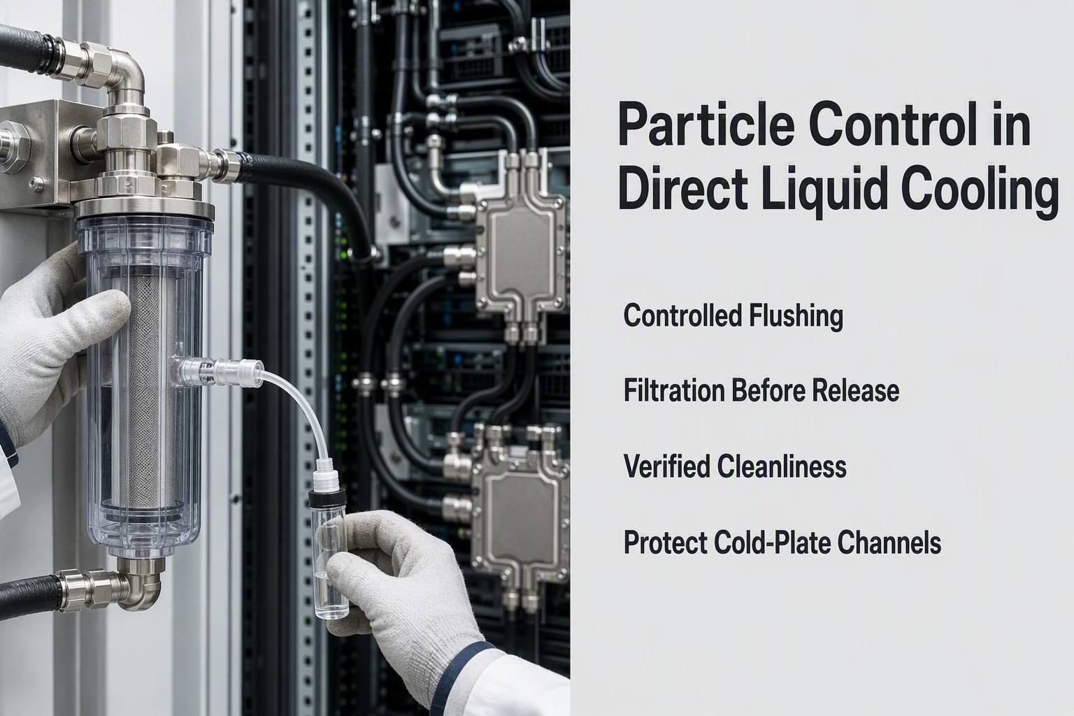
A direct liquid cooling loop can look clean and still contain particles capable of restricting a cold-plate header, holding a valve partially open, loading a filter, or wearing a pump surface. In an AI data center, the result may first appear as a branch temperature spread, unstable flow, rising filter differential pressure, intermittent valve operation, or a contamination pulse after a pump restart. Particle control is therefore not a final wipe-down task. It is a lifecycle process covering source control, flushing, filtration, sampling, and release.
This article is written for engineers working with AI servers, coolant distribution units, rack manifolds, cold plates, pumps, and service loops. It focuses on physical particle behavior and cleanliness verification. It does not repeat separate analyses of PTFE molecular bonding, UQD seal reliability, PUE optimization, thermal-expansion compensation, or coolant chemical compatibility. Any numerical example must be read with its stated fluid, flow, temperature, filter, sample, and measurement conditions.
Where Particles Come From
Common sources include cut tube ends, abrasion at hose insertion, machining chips, burrs, manifold cavities, weld or braze residue, loose oxide, valve-body debris, filter-housing residue, seal trimming flash, packaging fibers, protective-cap fragments, and particles carried by tools or gloves. The source matters because each mechanism needs a different control. Deburring does not solve packaging fibers; clean packaging does not remove a machining chip trapped in a branch; and a final visual inspection cannot prove that a suspended particle population is absent.
The installation process is often the point where clean components become a contaminated system. Open ports collect dust. Tube cutting creates an exposed end face. A connector cap can shed a fragment when removed. A tool can transfer metal dust into a manifold. A valve can release early actuation debris during its first cycles. The control plan should identify each open-port event, define how the component is protected, and specify what evidence is recorded before the loop is closed.
A component-level cleanliness statement is not an assembled-loop acceptance result. The final system contains more interfaces, branches, cavities, filters, pumps, and sample points than any individual part. The assembled loop must be flushed, stabilized, sampled, and functionally checked under declared conditions before it is released.
Table I. Particle Sources and Risk Levels
|
Source |
Typical mechanism |
Downstream risk |
Primary control |
Verification |
| Tube cutting and insertion | Cut fragments and abrasion | Cold plate or valve entry | Controlled cutting, caps, end inspection | Flush sample |
| Machined manifold | Chips, burrs, trapped media | Branches, pump, microchannels | Deburr, clean, inspect cavities | Rinse extraction |
| Welded or brazed assembly | Residue or loose scale | Filter loading and deposits | Process cleaning and protected storage | Filter inspection |
| Valve body and poppet | Machining or early wear debris | Stiction or seat obstruction | Pre-flush actuation and caps | Function and sample |
| Seal trimming and assembly | Flash, lint, lubricant-borne debris | Valve and seating surfaces | Clean handling and inspection | Magnified check |
| Packaging and service tools | Fibers, dust, metal particles | Any open branch | Clean-zone procedure | Maintenance record |
Risk categories are qualitative. No particle-generation rate is implied without a defined part, process, and measurement method.
The table separates source generation from downstream consequence. A particle may be created at a tube end, remain trapped in a manifold, and only move when the pump ramps. A chip may never appear in a return-line sample because it has already lodged at a valve seat. Source mapping should therefore include both generation points and likely retention points.
Controls should be physical and auditable: clean cutting tools, protected ports, deburred manifolds, controlled caps, clean work areas, pre-flush valve actuation, and inspection of cavities. “Clean before assembly” is incomplete unless the procedure defines the cleaning method, inspection location, acceptance condition, and responsibility.
The best point to remove a particle is before it enters a sensitive component. Once a particle reaches a microchannel header or valve clearance, the recovery path becomes more difficult and may require isolation, targeted flushing, component inspection, or replacement.
How Particles Move and Deposit
Particle behavior depends on size, shape, density, hardness, concentration, flow velocity, and receiving geometry. A nominal micron value is not enough. A rigid chip, flexible fiber, and agglomerated fine population may have similar measured dimensions but very different transport behavior. The same particle can remain suspended in a straight passage, impact an elbow, settle in a branch, and resuspend during a pump restart.
Reynolds number helps describe the carrier-flow regime, but it does not by itself predict deposition. Flow velocity, gravity, drag, wall interaction, and inertia must be considered with the actual geometry. Low-velocity pockets occur at manifold blind ends, elbow outlets, valve cavities, reducers, filter folds, and cold-plate inlets. These zones can accumulate particles while a sample from a fast-moving return line remains clear.
The critical comparison is between the particle population and the smallest sensitive opening: filter media, valve clearance, pump passage, cold-plate header, or microchannel entrance. Particles below a nominal filter rating may still agglomerate, load surfaces, or deposit in low-flow regions. Coarse chips can bridge an inlet or hold a valve seat open even when the average particle count is low.
What Contamination Does to the Cooling Loop
Cold-plate restriction often begins locally. A particle at a header or channel entrance changes resistance and redistributes flow among parallel paths. Total loop flow may remain normal while one branch receives less coolant and develops a localized temperature increase. A later rise in differential pressure can indicate that the restriction has grown, but temperature spread or branch-flow imbalance may be the earlier signal.
Pumps can suffer wear from hard particles circulating over time. The visible symptoms may be vibration, noise, reduced delivered flow, or increasing filter loading rather than immediate failure. Valve contamination is often intermittent: a particle in a clearance can cause stiction, incomplete opening, or incomplete closing. A hard inclusion at a seating surface can create a persistent scratch and bypass path.
Use combined evidence. A particle-count pulse after restart suggests resuspension. A rising filter differential pressure suggests capture or an increased source rate. A branch temperature spread with a clean return sample suggests that the sample may not represent a low-flow deposit. A valve force or flow change with no large count increase may indicate a retained particle in a cavity.
The Practical Filtration and Flushing Strategy
Circulation flushing mobilizes particles from the assembled loop and sends them to a controlled discharge or capture path. Staged branch flushing is safer when sensitive cold plates and valves should not receive the initial debris load. Bypass filtration can polish a reservoir or return path without placing the full flow through a fine element, but it does not guarantee protection for a local branch. Main-loop filtration protects downstream hardware directly, but it adds pressure drop and can load quickly during commissioning.
Temporary commissioning filtration is useful when the initial source load is unknown or expected to be high. The filter must be sized for flow, pressure-drop margin, dirt-holding capacity, and bypass behavior. A replacement event can itself recontaminate the loop if the housing, element, caps, or tools are not controlled. After opening the loop, perform a recovery flush and repeat the defined verification.
Chemical cleaning has a narrower boundary. It may be justified for a documented deposit or manufacturing film under a controlled procedure, but it does not replace particle capture, mechanical inspection, or circulation flushing. It should not be used as an undefined stronger-cleaning step.
Table III. Cleaning and Flushing Method Selection
|
Method |
Best use |
Main limitation |
Evidence before release |
| Directed circulation flush | Mobilize construction and assembly debris | May move particles into sensitive branches | Flow condition and discharge sample |
| Staged branch flush | Clean branches by sensitivity and sequence | Requires isolation and routing control | Branch sample and valve state |
| Bypass filtration | Polish reservoir or return path | May miss local branch deposits | Filter delta-P and count trend |
| Main-loop filtration | Capture circulating particles before targets | Adds restriction and can overload | Rating, capacity, bypass record |
| Temporary skid filter | Handle high initial commissioning load | Connection and removal can recontaminate | Skid delta-P and recovery sample |
| Chemical cleaning | Address documented film or deposit | Not a substitute for particle control | Rinse sample and inspection |
| Post-maintenance flush | Remove particles introduced by service | Requires controlled re-release | Stable sample and function check |
Method selection depends on component sensitivity, allowable flow direction, discharge control, filter capacity, and the project procedure.
No single method removes all contamination from all geometries. A flush cannot prove that a blind branch is clean if the flow never reaches it. A bypass filter cannot protect a cold plate from particles already circulating in the branch. A fine filter can become a restriction or open a bypass path if its loading is not monitored.
Treat commissioning, operation, and corrective cleaning as separate controls. Commissioning removes construction debris. Operational filtration limits residual circulation. Corrective cleaning responds to evidence of a deposit or particle pulse. This separation makes the acceptance record clear and prevents temporary filtering from being mistaken for a clean release.
Filter rating and pressure drop must be reported with fluid, temperature, flow rate, test method, and bypass condition. A finer element is not automatically better if it reaches bypass during the period of highest particle loading. Trend filter differential pressure at a known flow and record the removed element condition during maintenance.
Cleanliness Validation: From Flush to Release
Online particle counting, filter differential pressure, fluid sampling, filter-element inspection, visual inspection, and functional response measure different evidence. A particle counter sees what passes its sensor location. A differential-pressure sensor sees restriction across the element. A fluid sample is a time-and-location snapshot. A filter inspection shows captured material. A branch flow or temperature check shows whether contamination has created a system consequence.
A traceable sample record should include fluid, temperature, flow rate, filter rating, sample location, sample volume, stabilization condition, instrument calibration status, counting method, and the sequence of flushing and filter changes. A sample taken immediately after a pump restart is not equivalent to a stabilized return-line sample. The acceptance decision must state which condition was tested.
A practical release sequence is: inspect components; protect open ports; flush subassemblies; flush the assembled loop with staged filtration; stabilize at a defined flow; collect samples from defined points; inspect the filter; check branch flow and temperature response; exercise valves; and release only when the required evidence is repeatable. Any later open-port maintenance event resets the need for recovery verification.
Table V. Cleanliness Validation Method Matrix
|
Method |
What it shows |
Strength |
Limitation |
Release role |
| Online particle counter | Size-class count at a sensor point | Shows pulses and trends | Misses unmonitored branches | Trend and stabilization evidence |
| Filter differential pressure | Restriction across element | Continuous maintenance signal | Not a particle count | Loading and replacement trigger |
| Fluid sample | Particles in a defined sample | Independent snapshot | Location and timing limited | Acceptance and investigation |
| Filter-element inspection | Captured material and morphology | Source clues and confirmation | Only captured population | Root-cause review |
| Visual or magnified inspection | Surface debris and visible particles | Fast and practical | Cannot resolve all fine particles | Pre- and post-flush check |
| Branch flow and temperature | Functional effect of restriction | Detects system consequence | Not specific to particle cause | Cold-plate and loop release |
Acceptance limits must be defined by the project requirement, component sensitivity, counting method, and declared test conditions.
One clear sample is not proof of a clean loop. Particle release can be intermittent, and a fast return line can hide a low-speed branch deposit. Repeatability, stabilization, and sampling location are as important as the count itself.
Functional checks close the gap between measurement and performance. A cold plate can have a clean sample while retaining a local restriction. A valve can pass a count test while a retained particle causes intermittent stiction. Flow, temperature, pressure, and valve operation should be reviewed with contamination evidence.
The release record should be reusable. If a later investigation finds a particle pulse, the team needs to know the original flow state, filter condition, sample point, and instrument status. Without those fields, the original “clean” result cannot be meaningfully compared with the failure event.
FMEA Priorities and Engineer Checklist
The highest-value FMEA controls are specific and assignable. Cold-plate restriction requires inlet protection, branch-flow review, and targeted flushing. Pump wear requires source control and capture before the pump. Valve stiction requires protected ports, pre-flush actuation, and a function check. Filter overload requires capacity and differential-pressure limits. Maintenance recontamination requires clean tools, caps, recovery flushing, and re-release sampling. RPN is an illustrative prioritization method, not a certification result.
Request a Liquid Cooling Cleanliness Review
For an engineering review, provide the cooling-loop application, required flow rate, fluid and temperature range, filter rating, sampling method, cold-plate or CDU configuration, current particle symptom, recent maintenance event, and available differential-pressure or particle-count data. These inputs allow the likely source, transport path, filtration strategy, and verification plan to be reviewed together.
The objective is not to claim that a loop is clean from one visual check. It is to establish a repeatable cleanliness process that protects sensitive hardware before commissioning, after maintenance, and throughout operation.
Appendix FAQ
Q:Which components commonly generate particles?
A:Cut tube ends, machined manifolds, valve cavities, filter housings, protective caps, packaging, and installation tools are common sources. The actual ranking requires project-specific inspection and sampling.
Q:Can a loop look clean while particles remain?
A:Yes. Particles can settle in low-flow branches, valve cavities, elbows, filter folds, or cold-plate inlets and resuspend later.
Q:What particle size is dangerous to a cold plate?
A:There is no universal value without channel geometry, header design, particle shape, concentration, and flow condition. Compare the population with the smallest sensitive opening.
Q:When is bypass filtration useful?
A:It is useful for reservoir or return-path polishing when the main loop cannot accept additional restriction. It does not guarantee local branch protection.
Q:How should filter differential pressure be used?
A:Establish a clean-element baseline at a defined flow, trend it under comparable conditions, and define replacement or bypass actions from the approved hydraulic limits.
Q:Can chemical cleaning replace flushing?
A:No. It may address a documented film or deposit under a controlled procedure, but it does not replace particle capture, mechanical inspection, or circulation flushing.
Q:What should happen after a particle-count spike?
A:Check the sensor and sample condition, compare filter differential pressure, review pump or valve events, inspect the element, isolate sensitive branches if needed, and perform a controlled recovery flush.
Q:What data should be submitted for a cleanliness review?
A:Provide application, flow rate, fluid and temperature, filter rating, sampling method, component configuration, recent maintenance history, and available particle-count or differential-pressure data.
Post time: Aug-15-2026