
Executive Summary
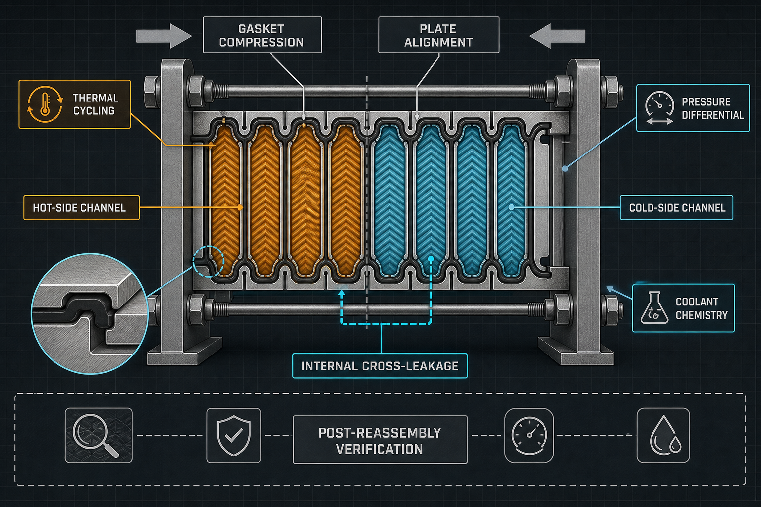
A plate heat exchanger in a liquid cooling CDU transfers heat while keeping two coolant circuits separated. Its gasket system must therefore control both external leakage and internal cross-leakage. A gasket can appear intact while losing contact stress, allowing hot-side and cold-side fluids to communicate through a local interface.
The governing chain is gasket material and geometry, compression, plate-pack alignment, thermal and pressure loading, sealing-force loss, fluid mixing and verification. Compression set, stress relaxation, thermal cycling, pressure differential, coolant chemistry, plate deformation and assembly error can act together. A post-maintenance pressure pass does not by itself rule out internal contamination risk.
Reliable control requires a defined sealing line, controlled plate compression, clean grooves and plates, compatible coolant exposure, repeatable reassembly and evidence that both leakage and cross-contamination boundaries remain acceptable.
Plate Heat Exchanger Gasket Sealing Principle
Gasket compression is the controlled deformation that creates contact stress between the gasket, the sealing groove and the mating plate. Plate-pack clamping force must maintain a continuous sealing line while the plates carry pressure and thermal loads. Elastic recovery provides contact reserve after deformation; compression set and stress relaxation reduce that reserve over time.
The seal must retain sufficient initial contact stress, suitable compression, continuous groove seating, stable plate alignment and a controlled plate gap. Temperature difference can move the plates and gasket at different rates, while pressure differential redistributes local contact stress. A groove particle, twisted gasket, displaced gasket or non-parallel frame can create a local leakage path even when the overall pack appears tight.
External leakage sends coolant outside the exchanger. Internal cross-leakage sends one circuit into the other. Gasket displacement, compression-set failure, plate deformation and assembly-induced leakage are different mechanisms and require different inspections. “Tightening the bolts” is not a complete diagnosis because the final interface depends on compression dimension, seating, surface condition and plate geometry.
Table I: Plate Heat Exchanger Gasket Structure and Failure Comparison
|
Gasket structure |
Sealing mechanism |
Compression behavior |
Thermal-cycle tendency |
Chemical limitation |
Maintenance requirement |
Main failure mode |
| Elastomer gasket | Elastic contact in groove | Recovery and set dependent | Aging and relaxation dependent | Compound-specific coolant limits | Replace and inspect seating | Set, swelling or displacement |
| PTFE-based gasket | Low-permeation contact or envelope seal | Lower elastic recovery in some designs | Movement and creep require control | Fluid and temperature specific | Surface and support inspection | Creep, leakage or damage |
| Reinforced gasket | Elastomer supported by reinforcement | Higher dimensional control | Interface still sees thermal strain | Reinforcement and coolant compatibility | Controlled installation | Local delamination or leak |
| Bonded gasket | Gasket fixed to plate surface | Repeatable placement if intact | Bond and gasket age together | Adhesive and coolant compatibility | Replacement may require cleaning | Bond failure or local channel |
| Replaceable design | Serviceable groove-seated gasket | Depends on seating and pack control | Reassembly history is critical | Replacement material must match | Defined replacement procedure | Wrong gasket, twist or misalignment |
These are screening categories rather than a universal ranking. Final selection must use the specific gasket, hardness, groove, plate geometry, coolant, temperature difference, pressure difference and maintenance method.
Gasket Aging and Compression Loss
Compression set is the permanent loss of recovery after long compression and dwell. Stress relaxation is the reduction in sealing force while the gasket remains deformed. Thermal aging can harden or soften the compound, and coolant exposure can cause swelling, extraction or chemical degradation. Repeated thermal cycling adds movement and strain to a contact that is already losing force.
The relevant influences include coolant temperature, hot-side and cold-side temperature difference, plate-pack compression, pressure differential, plate count, start-stop frequency, coolant chemistry, gasket hardness, cross-section and groove geometry. A gasket may first show compression-force loss, local seepage, a wet plate edge, pressure deviation, conductivity change or reduced heat-transfer performance before a large external leak appears.
Aging should not be reduced to calendar time. A gasket that survives a stable temperature may behave differently under frequent starts, pressure imbalance or a changed coolant formulation. Inspection should connect the symptom to recovery, surface condition, dimensions, plate alignment and fluid evidence.
Compression, Plate Pack and Assembly Control
Plate-pack compression must be controlled across the frame rather than applied as a single nominal tightening value. Insufficient compression reduces sealing-line contact stress; excessive compression can damage the gasket, distort a plate or injure a groove edge. Frame parallelism and plate alignment determine whether the compression is distributed or concentrated locally.
The tightening sequence, gasket seating, groove cleanliness and surface condition are part of the sealing design. A twisted or displaced gasket can form an internal channel. Particles on a groove or plate can hold the sealing surfaces apart. Reassembly can change plate order, orientation, pack dimension and final force distribution. Torque or hydraulic tightening must follow the equipment manufacturer’s specification for the actual plate count, gasket, design pressure and frame.
Maintenance records should capture the original pack condition, plate sequence, compression dimension, cleaning method, replacement gasket and final alignment. A fixed torque value should not be transferred between exchanger models without confirming the governing geometry and manufacturer limits.
Table II: Factors Affecting Gasket Compression and Aging
|
Factor |
Local mechanism |
Expected effect |
Potential failure risk |
Required measurement |
Recommended control method |
| Compression dimension | Sets initial contact stress | Contact reserve or damage | External or internal leakage | Final pack dimension and parallelism | Use approved compression limits |
| Plate-pack alignment | Redistributes gasket load | Local under- or over-compression | Sealing-line interruption | Frame and plate alignment | Control sequence and alignment |
| Temperature | Changes modulus and recovery | Force loss or hardening | Aging and thermal-cycle leakage | Hot/cold temperatures and history | Validate actual thermal envelope |
| Pressure differential | Changes local contact stress | Gasket displacement or extrusion | Internal cross-leakage | Hot/cold pressure trace | Control pressure relationship |
| Thermal-cycle frequency | Accumulates movement and strain | Recovery loss and fatigue | Post-cycle leakage | Cycle count, rates and dwell | Match duty and inspect after cycling |
| Coolant chemistry | Changes volume and material state | Swelling, softening or deposits | Leakage and contamination | Composition and conductivity | Qualify actual coolant |
| Gasket hardness | Changes deformation and recovery | Contact variation | Local seal loss | Hardness and batch record | Control approved compound range |
| Groove condition | Creates local gap or damage | Interrupted sealing line | Immediate or delayed leak | Visual and surface inspection | Clean and protect grooves |
| Reassembly sequence | Changes plate and gasket seating | Uneven final compression | Recurring maintenance leak | Sequence and final condition | Use controlled work instruction |
Compression and aging are coupled. Initial contact stress, plate alignment and gasket state determine how much sealing reserve remains after temperature, pressure and coolant exposure.
Cross-Contamination Between Hot and Cold Sides
Internal cross-leakage occurs when hot-side and cold-side fluids enter the wrong circuit without necessarily escaping to the environment. Causes include a local gasket channel, gasket displacement, a plate crack, plate deformation, pressure imbalance or chemical damage. Low-rate transfer may be difficult to see but can change coolant composition, conductivity, inhibitor concentration, deposits and heat-transfer behavior.
The diagnostic distinction is important. External wetting suggests a path to the environment; a hot-side or cold-side pressure deviation may suggest an internal communication path; conductivity or fluid-composition change can indicate mixing; temperature and flow changes can show circuit imbalance; and plate inspection can identify a structural defect. No single observation proves the mechanism.
Cross-contamination can affect corrosion control, particles or deposits, pump and valve condition, cold-plate performance and equipment stability. Verification must use the actual hot-side and cold-side media, pressure relationship and contamination criterion rather than relying on an external pressure test alone.
Table III: Cross-Contamination and Leakage Verification Matrix
|
Verification method |
Test objective |
Detectable failure |
Key parameter |
Main limitation |
Suitable maintenance stage |
| External pressure-hold | Check pressure boundary and outer leakage | Gross leak, loose joint or crack | Pressure, volume and stabilization | Limited for internal mixing | After assembly and repair |
| Hot/cold pressure comparison | Identify circuit communication | Pressure imbalance or cross-path | Both pressures and time history | Depends on operating boundary | Commissioning and troubleshooting |
| Conductivity monitoring | Detect coolant-property change | Possible fluid mixing or dilution | Baseline and trend by circuit | Indirect; chemistry dependent | Operation and maintenance |
| Fluid composition analysis | Confirm coolant transfer | Composition, inhibitor or additive change | Sample method and reference value | Sampling and laboratory delay | Troubleshooting and release |
| Temperature and flow comparison | Check thermal and hydraulic balance | Flow restriction or circuit disturbance | Inlet/outlet temperature and flow | Not specific to gasket leak | Commissioning and operation |
| Plate inspection | Find structural or seating damage | Crack, deformation or gasket path | Plate surface and sealing line | Requires disassembly | Corrective maintenance |
| Post-reassembly leak test | Confirm restored assembly | External leak and installation error | Test medium and acceptance basis | Does not cover all mixing risks | After gasket replacement |
| Thermal-cycle verification | Check stability after temperature change | Cycle-induced leakage or displacement | Range, rate, dwell and result | Requires defined representative cycle | After repair or design change |
The matrix separates evidence types. External pressure retention, fluid analysis, circuit comparison and plate inspection answer different questions and should be combined according to the suspected failure mode.
Inspection, Testing and Maintenance
A controlled gasket replacement begins with records, not disassembly. Record gasket material and hardness, plate count, pack dimension, design pressure, hot-side and cold-side pressure, coolant temperature, test medium, pressure-hold condition, conductivity or composition and the original reassembly state. Mark plate order and orientation before separation.
After removal, inspect the gasket, grooves, sealing lines, plate edges and contact surfaces. Remove deposits without creating scratches or embedded particles. Install the replacement gasket with controlled seating, rebuild the documented plate sequence, confirm compression dimension and frame parallelism, and perform the specified post-reassembly leak test.
The maintenance release should distinguish external leakage results from internal cross-contamination evidence. Where the risk justifies it, compare hot-side and cold-side pressure behavior, sample both coolants, check conductivity or composition, compare temperature and flow, and apply a representative thermal-cycle verification. Do not invent a precise result when no test data exist.
FMEA Risk Analysis
The FMEA should cover gasket compression set, insufficient or excessive compression, gasket displacement, plate misalignment, plate deformation, plate cracks, internal cross-leakage, external leakage, contaminated grooves, incorrect reassembly, wrong gasket material, pressure imbalance and incomplete post-maintenance inspection.
The RPN values below are illustrative engineering risk rankings, not field statistics or experimental results. They prioritize investigation and corrective action; they do not replace inspection evidence or circuit-specific contamination criteria.
Table IV: Plate Heat Exchanger Gasket FMEA and RPN Analysis
|
Failure mode |
Cause |
Local effect |
System effect |
Detection method |
RPN |
Corrective action |
| Compression set | Long compression and thermal exposure | Contact recovery declines | Delayed leakage or mixing | Gasket inspection and trend review | 170 | Review material and replacement interval |
| Insufficient compression | Incorrect pack dimension or alignment | Low contact stress | External or internal leakage | Dimension and pressure test | 180 | Correct compression and assembly control |
| Excessive compression | Over-tightening or wrong gasket | Gasket or plate damage | Recurring leakage | Pack dimension and visual inspection | 160 | Use approved assembly limits |
| Gasket displacement | Twist, poor seating or contamination | Local channel forms | Cross-leakage or external leak | Disassembly inspection | 175 | Improve seating and cleaning |
| Plate misalignment | Uneven tightening or frame condition | Uneven gasket load | Local seal failure | Parallelism and plate inspection | 165 | Control sequence and frame condition |
| Plate crack | Fatigue, corrosion or handling damage | Direct fluid path | Rapid or internal mixing | Visual, pressure and fluid analysis | 190 | Replace plate and investigate cause |
| Internal cross-leakage | Gasket path or plate defect | Circuits communicate | Coolant contamination | Pressure, conductivity and sampling | 195 | Isolate circuit and find path |
| External leakage | Outer seal path or assembly error | Coolant reaches environment | Loss of coolant and equipment risk | Pressure-hold and visual check | 180 | Repair seating and retest |
| Contaminated groove | Particles, deposit or cleaning residue | Local gap remains | Leak or recurring damage | Surface inspection and cleaning record | 150 | Clean and protect sealing line |
| Incorrect reassembly | Wrong plate order or orientation | Channels or seals mislocated | Performance loss or leakage | Sequence record and test | 165 | Use controlled work instruction |
| Wrong gasket material | Incorrect compound or hardness | Compatibility or recovery loss | Aging, leakage or contamination | Material and batch verification | 185 | Control approved material list |
| Pressure imbalance | Operating pressure relationship changes | Net force shifts seal | Internal cross-leakage | Circuit pressure monitoring | 175 | Define operating pressure boundary |
The corrective action should address the physical path, the assembly condition and the verification method. Lowering an RPN without controlling circuit-specific evidence does not reduce cross-contamination risk.
Conclusion
Plate heat exchanger sealing in a CDU is a system problem involving gasket material, geometry, compression, plate alignment, surface cleanliness, temperature difference, pressure difference, coolant chemistry, assembly quality and maintenance verification. External leakage and internal cross-leakage are different failure outcomes and must not share a single acceptance decision.
A reliable design maintains stable gasket compression, controlled plate alignment, compatible coolant exposure, thermal-cycle resistance, low external leakage risk, low internal cross-leakage risk and a repeatable maintenance condition. The final release decision should be supported by traceable reassembly records, leakage evidence and contamination checks appropriate to both circuits.
Engineering FAQ
Q:What causes gasket compression loss in a plate heat exchanger?
A:Long-term compression, stress relaxation, compression set, thermal cycling, coolant exposure, over-compression and uneven plate loading can reduce recovery or local contact stress.
Q:How can internal cross-leakage be distinguished from external leakage?
A:External leakage produces wetting outside the pack. Internal cross-leakage may instead appear as pressure imbalance, conductivity or composition change, flow disturbance or abnormal temperature behavior between the two circuits.
Q:How do temperature and pressure difference affect gasket aging?
A:Temperature changes material modulus, recovery and chemical aging, while pressure difference changes local contact stress and displacement risk. Their combined effect can accelerate a failure that neither condition produces alone.
Q:Why is plate-pack alignment important for gasket sealing?
A:Alignment determines whether compression is distributed along the sealing line. A non-parallel or misaligned pack can over-compress one region while leaving another below the required contact stress.
Q:Which tests are necessary after gasket replacement?
A:At minimum, perform the specified external leak test and verify the final pack condition. Where cross-contamination matters, add circuit pressure comparison, coolant sampling or conductivity checks, and representative thermal verification.
Q:Can a pressure-hold test rule out all cross-contamination risks?
A:No. It can show pressure retention under its defined setup, but it does not automatically exclude internal mixing, low-rate transfer, chemistry changes or a plate defect.
Post time: Aug-26-2026