
Executive Summary
A VCR face seal contains process gas through controlled metal-gasket seating between two prepared sealing faces. Its reliability depends on gasket condition, face finish, alignment, assembly load, gas compatibility, cleanliness and verification. It is not a generic pipe-thread seal and should not be judged by pressure stability alone.
A fitting may appear correctly assembled while a scratch, particle, reused gasket, uneven load or thermal-cycle shift creates a microleak path. The engineering record should distinguish design expectation, assembly condition, laboratory leak result, field service condition and maintenance conclusion. A passing pressure-hold test does not automatically exclude a small leak, virtual leak or contamination source.
VCR Face-Seal Architecture and Sealing Mechanism
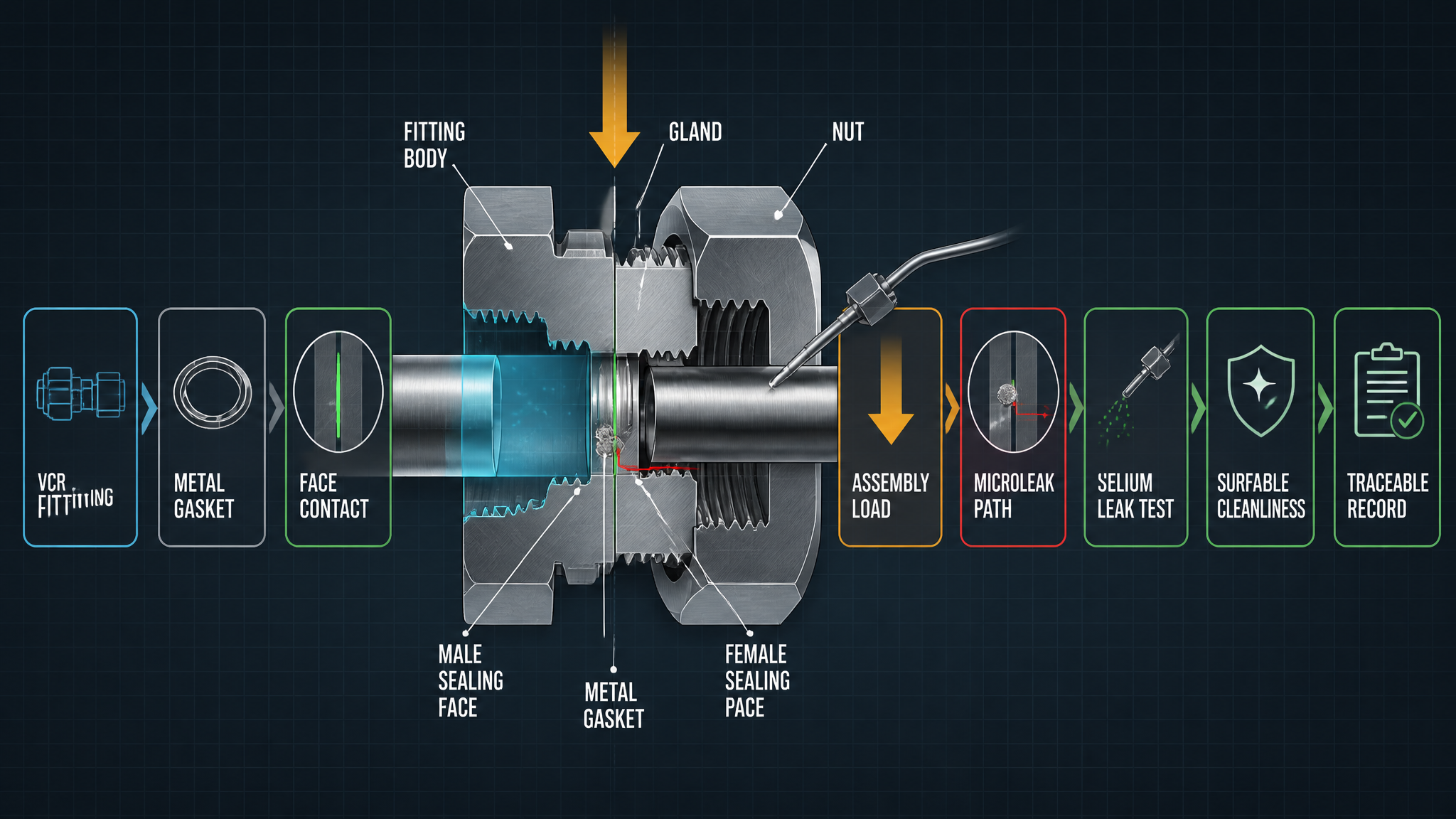
A VCR connection uses a fitting body, gland, nut and metal gasket. The body and gland locate the male and female sealing faces. The nut transfers an axial assembly load through the fitting, while the gasket deforms locally to establish a continuous metal-to-metal contact path. Gas containment is created at the face interface, not by the threads themselves.
This differs from a threaded seal, a tapered tube seal and an elastomeric seal. Threads primarily provide engagement and load transfer; they do not by themselves define a clean face-sealing line. Tapered or compression joints depend on different contact geometry. Elastomeric seals rely on elastic recovery and are more sensitive to compression set, permeation and chemical swelling. A VCR gasket is a controlled-use sealing element: after disassembly, its deformation and surface history may no longer support the original sealing condition.
The seating process should be understood as a load path rather than as a single tightening action. The nut load is transferred through the fitting into the gland and gasket, while the mating faces constrain the gasket deformation. If the fitting is not coaxial, part of the load may be consumed by side reaction or face tilt instead of producing uniform contact. Pipe strain, unsupported weight and adjacent thermal movement can therefore affect a connection that was assembled correctly at room temperature. A repeatable assembly procedure controls engagement, alignment, load application and inspection sequence; it does not rely on the operator’s final feel alone.
The sealing face is also a geometric interface. A scratch may act as a continuous channel, while a particle may create a localized opening that disappears or changes when the fitting is disturbed. A transfer mark can indicate contact, but it does not by itself prove that the complete circumference is uniformly seated. Face inspection should be interpreted together with gasket history, fitting alignment and the leak-test result.
Table I: VCR Face-Seal Structure and Function
|
Component |
Sealing function |
Main load |
Typical risk |
Verification focus |
| Fitting body | Supports pressure boundary | Pressure and assembly reaction | Deformation or damage | Dimensions and surface |
| Gland and faces | Locate contact line | Axial seating load | Misalignment or scratches | Face and alignment check |
| Nut | Transfers assembly load | Controlled tightening load | Under- or over-tightening | Assembly record |
| Metal gasket | Conforms at contact line | Local contact stress | Reuse, damage or distortion | Pre/post leak test |
| Gas boundary | Isolates process gas | Pressure differential | Microleak or contamination | Helium verification |
The gasket is only one part of the boundary. Face condition, alignment and controlled loading determine whether its deformation becomes a continuous sealing path.
Microleak Mechanisms
A microleak can form when the sealing face is scratched, a foreign particle interrupts contact, a gasket is reused, or the assembly load is uneven. Under-tightening may leave incomplete seating. Over-tightening may damage the gasket or face and create a permanent leak path. Misalignment can concentrate load at one side while leaving another side under-seated.
Thermal cycling can change dimensions and contact reserve. Pressure cycling can repeatedly load the gasket and fitting. Corrosion or surface attack can alter the face even when the connection remains mechanically tight. Improper disassembly can score the face or place particles on the sealing line.
The diagnosis must distinguish an external microleak from internal gas leakage, a virtual leak, outgassing and surface contamination. A real leak connects the gas boundary to an external region. A virtual leak releases trapped gas from a cavity or contaminated interface. Outgassing is material release under vacuum and does not require a through-path. Surface contamination may affect cleanliness or test stability without being the primary leak path.
Installation-induced leakage often has a different signature from material incompatibility. A leak that appears immediately after assembly, follows a changed operator or tool sequence, or disappears after controlled replacement is consistent with surface, gasket or assembly causes. A leak that develops after exposure to a reactive gas, thermal history or pressure cycling requires a broader compatibility and mechanism review. These observations are useful clues, not proof; confirmation still requires controlled retest and physical inspection.
A pressure-hold result can also be misleading when the system volume is large, the pressure change is small, the temperature is drifting or gas is trapped in a dead volume. A stable pressure trend may coexist with a small leak below the resolution of the setup. Conversely, a pressure change may come from temperature or desorption rather than a through-leak. Helium testing and pressure-hold testing should therefore be treated as complementary methods with different detection boundaries.
Table II: Microleak Mechanisms and Control Measures
|
Failure mechanism |
Likely cause |
Local effect |
Detection method |
Corrective action |
| Scratched face | Tool contact or handling | Broken contact line | Microscopy and helium test | Replace or control surface |
| Foreign particle | Poor cleaning or handling | Point gap | Surface and particle review | Clean and reassemble |
| Gasket reuse | Prior deformation | Reduced conformity | Teardown and leak test | Use controlled replacement |
| Under-tightening | Insufficient assembly load | Incomplete seating | Assembly review and helium test | Follow approved procedure |
| Over-tightening | Excessive assembly load | Face or gasket damage | Surface and force review | Replace damaged parts |
| Misalignment | Pipe strain or poor engagement | Uneven contact stress | Alignment inspection | Correct alignment first |
| Thermal-cycle leakage | Differential expansion | Contact reserve loss | Pre/post thermal leak test | Review material and cycle envelope |
| Corrosion or residue | Reactive exposure or moisture | Surface attack | Surface and gas analysis | Remove source and requalify |
The control method must address the physical cause, not only the final leak symptom.
Process-Gas Compatibility and Cleanliness
Gas chemistry, temperature, pressure, moisture and reactive species can change the condition of a metal gasket and its sealing faces. Material selection is conditional on the actual process envelope. 316L stainless steel, nickel-based alloys or other metal options may be suitable in selected services, but no material should be treated as universally compatible with every gas, temperature, pressure or cleanliness requirement.
Cleaning residue, particles, poor storage and damaged packaging can create a microleak or a contamination event. Gaskets should remain protected until installation. Clean gloves, dedicated tools and controlled handling reduce the chance that a particle or residue reaches the face. Compatibility review should consider corrosion, surface passivation, thermal exposure and the consequences of trace contamination. Gas compatibility is not only a bulk-material question. A reactive species may attack a damaged surface, a residue or a coating defect preferentially, while moisture or oxygen ingress may change the condition of a previously stable interface. The assessment should therefore include gas purity, expected excursions, storage atmosphere and the cleaning process used before installation.
Gasket storage is part of contamination control. Packaging damage, uncontrolled exposure, mixed batches or contact with unsuitable tools can change the gasket before it reaches the fitting. Retaining the batch and handling record helps separate a material issue from a single installation event. It also supports a controlled response when a repeated leak pattern appears across otherwise similar assemblies.
Assembly, Alignment and Maintenance Control
Inspect both sealing faces before assembly. Confirm gasket identity, condition and orientation; engage the fitting without cross-loading; and keep the connection aligned before applying assembly load. Tightening must follow the actual fitting specification and approved procedure. A fixed torque value must not be presented as a universal VCR standard.
Under-tightening can produce incomplete contact. Over-tightening can damage the face or permanently deform the gasket. After disassembly, inspect the face for scratches, transfer marks, particles and corrosion. A used metal gasket should normally be treated as a controlled-use sealing element rather than an automatically reusable part.
After gasket replacement, retain the fitting type, gasket material and batch, gas service, assembly record, installation date, surface condition, leak-test method and result. Post-maintenance verification should match the changed risk; one pressure-hold result is not sufficient evidence for every microleak condition.
Leak Testing and Verification
Helium mass-spectrometer leak testing is suited to small leak-path verification when the test boundary, helium access, instrument sensitivity and procedure are controlled. Positive-pressure, vacuum-side and local detection arrangements answer different questions. Pressure-hold testing can identify larger leakage or pressure instability, but temperature change, system volume, trapped gas and instrument resolution may mask a small leak.
Thermal- and pressure-cycle verification checks whether the connection remains stable after representative loading. Face inspection, gasket teardown, particle inspection and pre/post-maintenance comparison help distinguish assembly-induced leakage from material incompatibility, surface damage, outgassing or contamination.
The leak-test record should identify the test boundary, test direction, connection state, helium application method, instrument status, environmental condition and acceptance basis. A result without this context is difficult to compare across maintenance events. Pre- and post-maintenance comparison is most useful when the same boundary definition and measurement procedure are retained.
If a connection fails after a thermal or pressure cycle, do not immediately assign the cause to the gasket material. Check whether the fitting moved, whether adjacent tubing imposed strain, whether the face was damaged during disassembly, whether the gasket was reused and whether the test arrangement introduced a virtual leak. Mechanism-based troubleshooting reduces unnecessary part substitution and preserves traceability.
Table III: VCR Assembly and Leak-Test Verification Guide
|
Test or inspection |
Test purpose |
Key variable |
Detectable issue |
Main limitation |
| Face inspection | Check sealing surface | Scratches, particles, flatness | Damaged or dirty face | Does not prove assembly leakage |
| Gasket inspection | Confirm gasket condition | Material, batch, deformation | Wrong, reused or damaged gasket | Visual check may miss microdamage |
| Alignment check | Verify engagement | Axis, face position, pipe strain | Uneven seating | Requires a controlled datum |
| Helium leak test | Verify leak boundary | Test mode, sensitivity, result | Microleak under test condition | Boundary-specific |
| Pressure hold | Check pressure stability | Pressure, time, temperature | Larger leak or instability | May miss small or masked leaks |
| Thermal or pressure cycle | Check post-cycle stability | Range, dwell, cycle history | Relaxation or cycle leakage | Must match service envelope |
| Post-maintenance review | Confirm restored condition | Surface, assembly, leak result | Installation-induced issue | Scope must match the repair |
No single test proves complete process-gas reliability. The evidence must connect surface condition, gasket history, assembly record, leak result and service exposure.
Data Interpretation and Maintenance Planning
Retain records for fitting type, gasket material and batch, gas service, pressure, temperature, surface condition, alignment, assembly procedure, installation date, leak-test method and result, thermal or pressure-cycle history, disassembly findings, contamination findings and corrective action.
Maintenance may be calendar-based, condition-based, leak-trend-based, risk-based or triggered by gasket replacement. A laboratory result should not be converted directly into a universal field life. The decision must reflect gas hazard, cleanliness requirement, service severity, monitoring capability and the consequence of a microleak. Maintenance planning should also define what triggers escalation: a failed leak test, a changed leak trend, visible face damage, an unknown gasket history, a contaminated package or an assembly record that cannot be reconstructed. These triggers are more defensible than an unsupported replacement interval.
FMEA Risk Analysis
The RPN values below are illustrative engineering risk rankings, not field statistics or experimental results.
Table IV: VCR Face-Seal FMEA and RPN Analysis
|
Failure mode |
Cause |
Local effect |
System effect |
Detection method |
RPN |
Corrective action |
| Damaged sealing face | Scratch or impact | Broken contact path | Process-gas microleak | Microscopy and helium test | 180 | Replace or control surface |
| Contaminated interface | Particle or residue | Local gap | Leak and contamination | Cleanliness inspection | 170 | Clean and reassemble |
| Gasket reuse | Prior compression or damage | Reduced conformity | Repeated leakage | Batch and teardown review | 165 | Controlled replacement |
| Incorrect gasket material | Selection or traceability error | Incompatible interface | Corrosion or leakage | Record and compatibility review | 175 | Verify material control |
| Misalignment | Pipe strain or poor engagement | Uneven load | Local microleak | Alignment inspection | 175 | Correct alignment |
| Under-tightening | Insufficient load | Incomplete seating | Gas leakage | Assembly record and helium test | 180 | Follow procedure |
| Over-tightening | Excessive load | Face or gasket damage | Permanent leakage risk | Surface review | 175 | Replace and review process |
| Thermal-cycle leakage | Differential expansion | Contact reserve loss | Post-cycle microleak | Thermal leak test | 165 | Review service envelope |
| Inadequate post-maintenance test | Pressure check only | Hidden defect remains | Recurring leakage | Requalification audit | 180 | Match test to changed risk |
| Poor gasket storage | Damage, moisture or contamination | Altered face condition | Leakage or particles | Storage and pre-use inspection | 145 | Improve packaging and control |
Corrective action should improve the physical interface, the assembly process and the verification rule together.
Conclusion
VCR process-gas face sealing depends on controlled metal-gasket seating, clean and undamaged faces, correct alignment and a recorded assembly procedure. Microleaks can arise from scratches, particles, gasket reuse, uneven loading, thermal cycling, corrosion or maintenance damage. They cannot all be attributed to material aging.
Helium leak verification is a key tool, but its result remains bounded by the test configuration. Pressure-hold, thermal-cycle, surface, cleanliness and teardown evidence provide complementary information. High-purity process-gas reliability is achieved through controlled fitting geometry, gasket history, assembly traceability, compatible materials and post-maintenance requalification.
Engineering FAQ
Q:How does a VCR metal gasket create a gas-tight face seal?
A:The nut applies axial load through the fitting, deforming the metal gasket locally between prepared male and female faces. The resulting continuous contact line forms the gas boundary.
Q:Why can particles or scratches cause a VCR microleak?
A:They interrupt the metal contact line and create a local gap or point load. Even a small defect can prevent uniform seating across the face.
Q:Can a used metal gasket be reused after disassembly?
A:It should not be assumed reusable. Prior deformation, scratches and contamination may prevent the original contact condition from being restored. Reuse requires a defined engineering procedure, not visual confidence alone.
Q:Why is helium leak testing preferred for microleak verification?
A:Helium provides a traceable test gas for mass-spectrometer detection of small leak paths under a controlled boundary. The method still depends on correct setup and acceptance criteria.
Q:Can a pressure-hold test replace helium leak testing?
A:Not generally. Pressure hold can reveal larger leakage or instability, but temperature, volume and trapped gas may mask a small leak. The methods answer different questions.
Q:What should be recorded after VCR gasket replacement?
A:Record fitting type, gasket material and batch, gas service, surface condition, assembly procedure, installation date, leak-test method and result, and any contamination or corrective-action findings.
Post time: Aug-28-2026