
Executive Summary: Why Initial Sealing Does Not Guarantee Long-Term Sealing
A PTFE bolted joint can pass an initial pressure-hold test and later leak without visible nut rotation. The test proves containment only at its defined pressure, temperature, assembly condition and duration; it does not prove contact-pressure retention after compression, thermal cycling, pressure cycling or chemical exposure.
The engineering question is whether the joint retains a sufficient, distributed contact-pressure field while PTFE deforms, interfaces settle, bolts change length and the flange rotates. Leakage should be investigated as a joint-system event rather than assigned automatically to PTFE cold flow.
Long-term compression stability is therefore a system property. Material formulation affects deformation rate, but gasket geometry controls restraint; flange stiffness controls rotation; bolt stiffness controls load redistribution; surface condition controls local continuity; and operating history controls how often the weak zones are challenged. A sound conclusion must identify which of these variables was measured, which was assumed and which remains uncertain.
Bolted-Joint Architecture and the Initial Contact-Pressure Field
Bolt elongation and nut-washer reaction create clamp load. The flange transfers it into PTFE compression, while connected equipment and piping add moments, misalignment and restraint. Bolt, flange, gasket and external structural stiffness therefore act as one coupled system.
Contact pressure must resist process pressure across the sealing width, but it is not uniform: bolt-hole regions, gasket edges, surface damage and flange rotation create different local loads. High average compression can still contain a low-pressure path, so design must address initial seating and load retention.
The sealing interface is a pressure boundary within a larger mechanical system; average torque or compression cannot describe every local condition.
The relevant boundary is not only the gasket material. It includes the flange face, the compressed gasket width, the bolt-hole region, the connected equipment and the external environment. Internal pressure attempts to open or penetrate the interface, while the clamp load must maintain contact around the entire leakage path. If a local zone loses compression, the rest of the joint may remain apparently tight while that zone controls system leakage.
Gasket width and restraint determine how far PTFE can move when local stress exceeds the available constraint. A narrow element may reach the required seating pressure with less stored material, but it can be more sensitive to surface error or edge extrusion. A wider element may provide more contact area, yet it can require greater flange stiffness to maintain uniform compression. These are joint-design trade-offs, not universal material rankings.
PTFE Creep, Cold Flow and Stress Relaxation
Creep is time-dependent deformation under sustained stress. In a compressed PTFE gasket it appears as thickness reduction, edge movement or material migration. Cold flow is the practical joint-level description of this movement; it is not a replacement for creep analysis.
Stress relaxation is a reduction in material stress while deformation is held or constrained. PTFE can lose sealing stress without visible nut rotation. Compression set is retained deformation after unloading, while recovery is the ability to regain contact pressure after load or temperature changes. These terms are related but not interchangeable.
Temperature, formulation, thickness, width, restraint, compression and chemical exposure affect the result. Filled or modified PTFE may improve compression stability while changing recovery, friction or compatibility. No fixed compression, temperature or duration is a universal PTFE criterion without material and joint-specific evidence.
| Mechanism | Physical description | Joint-level consequence | Observable evidence | Main limitation |
| Creep | Time-dependent deformation under sustained stress | Gasket thickness or shape changes | Thickness change or material migration | Rate depends on material and load |
| Cold flow | Practical gasket movement under compression | Contact pressure redistributes | Edge movement or extrusion marks | Term is not a complete model |
| Stress relaxation | Stress decreases while strain is constrained | Sealing stress falls with time | Preload or contact trend changes | Needs defined strain and temperature |
| Compression set | Permanent deformation after unloading | Reduced recovery on reassembly | Residual thickness loss | Test result may not represent joint geometry |
| Recovery loss | Reduced ability to restore contact | Leakage after cycling or maintenance | Weak gasket imprint or gap | Depends on formulation and damage |
Creep, cold flow, stress relaxation, compression set and recovery describe different parts of the material and joint response.
For design interpretation, the distinction is practical. A creep observation describes movement under a sustained load; a stress-relaxation result describes stress loss under a constrained deformation; a compression-set result describes what remains after unloading. None of these alone predicts the contact pressure in a particular flange. The joint must be evaluated with its actual thickness, width, restraint, surface condition and temperature history.
From PTFE Compression Loss to Bolt Preload Redistribution
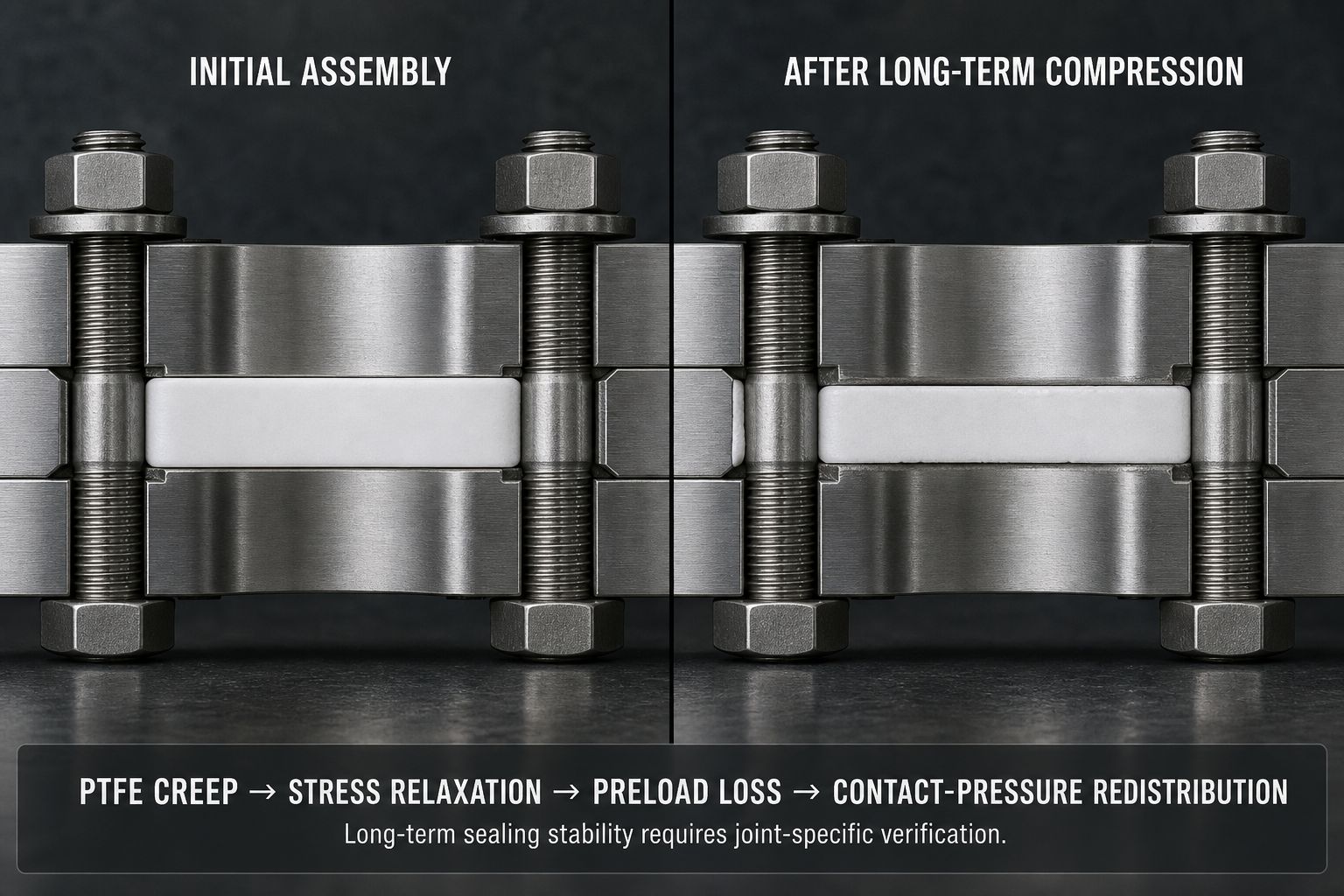
When PTFE loses thickness or redistributes, part of the original assembly displacement is consumed by gasket deformation rather than retained as elastic bolt elongation. Flange movement changes bolt extension and the balance between bolt force and gasket reaction; embedment and surface flattening consume additional displacement.
Preload loss therefore does not require nut rotation. Axial preload can decline through gasket compression loss, embedment, flange deformation, bolt relaxation or differential expansion. A lower torque reading does not prove proportional axial-force loss because torque depends on friction, lubrication, surface condition and measurement method. Torque is indirect; axial preload requires suitable verification.
Excessive preload can damage PTFE, promote extrusion and distort the flange. Insufficient or uneven preload can leave low-pressure zones that worsen during cycling. Joint stiffness, not the bolt alone, governs redistribution.
The same gasket thickness loss can produce different preload changes in different joints. A stiff flange and compliant bolt may retain a different load path from a flexible flange and highly elongated bolt. Surface embedment can also appear as preload loss even when the bolt material has not relaxed. This is why bolt, flange and gasket data must be interpreted together rather than compared with a single torque target.
Leakage Transition Under Temperature, Pressure and Chemical Exposure
Leakage begins when a continuous sealing path is lost or when transport occurs through or around the gasket. Seating loss can follow contact-pressure reduction, flange rotation, surface damage, contamination or gasket eccentricity. Extrusion and blowout differ from uniform creep because they involve local loss of restraint or movement toward a lower-pressure region.
Permeation is transport through material or a microscopic path, not necessarily external flange leakage. Internal and external leakage have different consequences. Pressure decay may reflect leakage, temperature change, test-volume effects, fluid compressibility or instrument resolution; diagnosis requires the test record and physical evidence.
A useful failure investigation first defines the observed symptom, then asks whether the sealing path was opened, weakened or bypassed. A damaged face points toward a boundary defect; edge migration points toward extrusion or inadequate restraint; a gradual trend after a temperature hold points toward relaxation or thermal redistribution; a leak that follows medium exposure may require compatibility and permeation review. These hypotheses must remain conditional until inspection supports them.
PTFE and metal respond differently to temperature. Thermal expansion changes gasket compression, bolt elongation and flange rotation; a cycle may gain load in one phase and lose local contact in another. Higher temperature generally accelerates PTFE time-dependent deformation, while low temperature can change recovery and joint stiffness.
Pressure cycling can open a marginal interface, enlarge an extrusion path or expose uneven compression. Start-stop operation combines temperature and pressure transients. Chemical exposure can add permeation, extraction, filler interaction, swelling or dimensional change. Evaluation must use the actual medium, concentration, temperature, pressure and duration; no fixed cycle count is universal.
| Operating factor | Direct effect | Load-redistribution effect | Potential leakage mechanism | Required evidence | Interpretation limit |
| Sustained compression | PTFE time-dependent deformation | Gasket load decreases or moves | Seating loss or extrusion | Thickness and imprint | Rate is formulation-specific |
| Temperature cycling | Differential expansion | Bolt and flange loads vary | Thermal-cycle leakage | Temperature and preload history | Local gradients may be unknown |
| Pressure cycling | Repeated interface loading | Marginal zones open and close | Pressure-cycle leakage | Pressure trend and leak test | Must represent service |
| Chemical exposure | Permeation or dimensional change | Contact geometry changes | Swelling or leakage path | Compatibility and residue review | Depends on medium and time |
| Uneven tightening | Non-uniform initial compression | Local low and high load zones | Leakage or extrusion | Sequence and preload data | Torque alone may mislead |
Operating factors often amplify a pre-existing weak zone instead of creating a completely new failure mechanism.
Thermal cycling also changes the meaning of a preload measurement. A load recorded at assembly, at ambient temperature and after a hot or cold excursion may not be directly comparable unless the joint temperature and measurement method are controlled. Pressure-cycle leakage can occur when a marginal contact zone repeatedly changes state, while chemical exposure can alter dimensions or friction without producing an immediately visible defect. The operating history is part of the failure evidence.
Diagnostic Evidence and Mechanism-Specific Verification
Post-service evidence should be interpreted as a set. Verified axial preload is more informative than torque alone, but still needs gasket imprint and flange condition. Thickness loss, edge migration, extrusion, cracks, residue and asymmetric compression help separate material deformation from assembly error or flange distortion.
If the nut has not moved but preload declined, investigate compression loss, embedment, bolt relaxation and flange movement. If torque declined without proportional axial-load change, investigate friction and measurement. If pressure decays with temperature, review temperature, test volume and instrument accuracy. A one-sided imprint requires review of alignment, flatness, sequence and flange rotation before re-tightening.
The objective is not to find one dramatic clue but to build a consistent chain. Compare original gasket dimensions with recovered thickness, map the imprint around the circumference, record edge extrusion, inspect the flange face for scratches or transferred material, and compare bolt condition and lubrication with the assembly record. If the physical evidence does not match the proposed mechanism, the maintenance action should remain open rather than forcing a premature diagnosis.
Verification should answer a defined question. An initial pressure hold checks containment at its test condition; long-term monitoring checks stability. Pressure decay requires temperature compensation and instrument review. Helium, pneumatic and hydrostatic tests have different sensitivity and safety boundaries, while thermal and pressure cycles should represent service loads.
Preload can be reviewed by torque audit, ultrasonic bolt elongation, a load-indicating washer or another suitable method; these are not interchangeable. Teardown should record thickness, imprint, extrusion, cracking, local compression, surface damage and flange condition, separating true leakage from test-system effects.
| Test or inspection | Test objective | Key variable | Detectable issue | Suitable stage | Main limitation |
| Initial pressure hold | Confirm initial containment | Pressure, time and temperature | Static leakage | Assembly or qualification | Does not prove long-term stability |
| Pressure-decay test | Track boundary pressure change | Temperature and instrument drift | Leakage or false decay | Qualification and service | Requires compensation |
| Thermal-cycle test | Assess load response to temperature | Cycle profile and preload | Thermal-cycle leakage | Qualification | Must represent service |
| Preload verification | Assess axial clamp load | Elongation or load signal | Preload loss or uneven load | Assembly and maintenance | Torque is only indirect |
| Gasket inspection | Assess deformation and seating | Thickness, imprint and extrusion | Creep, damage or misalignment | Teardown | Destructive evidence |
| Surface inspection | Confirm contact boundary | Flatness, damage and cleanliness | Leak path or contamination | Assembly and maintenance | Does not prove cycling |
No single test proves initial containment, preload retention, material stability, thermal stability and chemical compatibility at the same time.
Material, Geometry and Maintenance Decisions
Virgin, filled, modified and expanded PTFE, envelope gaskets and supported structures should be compared by creep resistance, recovery, compatibility, permeation, extrusion resistance, surface conformity, friction and thermal response. A formulation that excels in one criterion may create an installation or compatibility limitation; there is no universal best solution.
Gasket geometry and centering must match flange flatness, parallelism, surface condition and bolt-load distribution. Record lubrication and sequence because friction changes the torque-to-force relation. Re-tightening may restore compression temporarily but cannot remove extrusion, gasket damage, flange distortion, surface defects or chemical change.
Do not automatically reuse a removed PTFE gasket. After maintenance, confirm material, dimensions, orientation, centering, clean surfaces, bolt and washer condition, lubrication, alignment and preload verification. Requalification should include the relevant pressure, temperature or leakage check.
FMEA: From Preload Loss to Leakage
The RPN values are illustrative engineering risk rankings, not field statistics or experimental results. They prioritize inspection and corrective action; they do not represent a universal failure probability.
| Failure mode | Cause | Local effect | System effect | Detection method | RPN | Corrective action |
| PTFE creep | Sustained compression and time | Thickness or shape change | Contact-pressure loss | Thickness and teardown | 216 | Review formulation and restraint |
| Stress relaxation | Time and temperature | Sealing stress decreases | Leakage after hold period | Long-term preload trend | 198 | Use time-temperature evidence |
| Bolt preload loss | Gasket loss, embedment or relaxation | Lower clamp load | Local sealing failure | Axial preload check | 210 | Verify load and joint stiffness |
| Flange rotation | External moment or low stiffness | Uneven face pressure | Edge leakage | Flatness and imprint | 192 | Review alignment and support loads |
| Gasket extrusion | Excess load or weak restraint | Material moves to edge | Blowout or leakage path | Teardown inspection | 204 | Correct geometry and preload |
| Uneven tightening | Friction or sequence error | Local high and low zones | Early leakage or damage | Sequence and load record | 180 | Control method and lubrication |
| Chemical dimensional change | Incompatible medium or filler | Swelling or embrittlement | Permeation or leakage | Compatibility and residue review | 175 | Validate material and medium |
| Inadequate verification | Test scope too narrow | Failure mechanism remains | Repeat maintenance event | Record audit | 205 | Use mechanism-specific checks |
Engineering Decision Rules,Conclusion and FAQ
If the pressure test passes but axial preload is unverified, long-term stability remains unconfirmed. If torque decreases but gasket morphology is unknown, do not assign the change to PTFE creep alone. If leakage appears after thermal cycling, inspect differential expansion, flange rotation and preload history before re-tightening. If extrusion is visible, re-tightening is not a complete corrective action.
If the imprint is uneven, review alignment, flatness, gasket centering and tightening sequence. If pressure decay follows temperature change, separate thermal effects from true leakage. If the joint is reassembled, treat preload, gasket condition, surface condition and sealing verification as a new engineering event. These rules keep the corrective action tied to evidence rather than to a single convenient explanation.
Conclusion
PTFE creep and cold flow change the gasket; gasket deformation changes joint stiffness; joint stiffness changes bolt preload; preload redistribution changes contact pressure; contact-pressure loss creates leakage risk. Stress relaxation, embedment, flange deformation, thermal expansion, cycling and chemical exposure can act together without nut rotation.
Long-term stability requires a defined joint architecture, suitable PTFE formulation and geometry, controlled assembly, mechanism-specific preload and leakage verification, and maintenance records linking material condition to sealing performance.
Engineering FAQ
Q:What is the difference between PTFE creep and stress relaxation?
A:Creep is time-dependent deformation under sustained stress. Stress relaxation is the reduction of stress while deformation is held or constrained. A compressed gasket can exhibit both at the same time.
Q:Why can a PTFE flange joint pass an initial pressure test but leak later?
A:The initial test may pass before PTFE compression loss, stress relaxation, embedment, thermal cycling or pressure cycling changes the contact-pressure distribution.
Q:Does bolt torque directly represent actual bolt preload?
A:No. Torque is affected by thread friction, nut friction, lubrication, surface condition and tool variation. Axial preload requires a suitable verification method.
Q:How does PTFE cold flow reduce long-term contact pressure?
A:Time-dependent material movement can reduce thickness, shift load toward less constrained regions and create local low-pressure zones or extrusion paths.
Q:Can re-tightening permanently solve PTFE gasket leakage?
A:No. It may temporarily restore compression, but it cannot remove extrusion, gasket damage, flange distortion, surface defects or chemical dimensional change.
Q:How do temperature cycles affect PTFE gasket compression and bolt load?
A:Differential expansion changes bolt elongation, flange rotation and gasket compression. The joint may gain load in one phase and lose local contact in another.
Q:Which PTFE formulations provide better resistance to long-term compression loss?
A:Filled or modified formulations may improve creep resistance, but the choice depends on recovery, chemical compatibility, permeation, extrusion resistance, temperature and installation conditions.
Q:What should be inspected before replacing a PTFE gasket?
A:Inspect the flange face, flatness, alignment, bolt and washer condition, threads, lubricant, gasket dimensions, surface cleanliness and the cause of the original leakage.
Post time: Sep-02-2026