
Executive Summary: The Invisible Load on AI Infrastructure
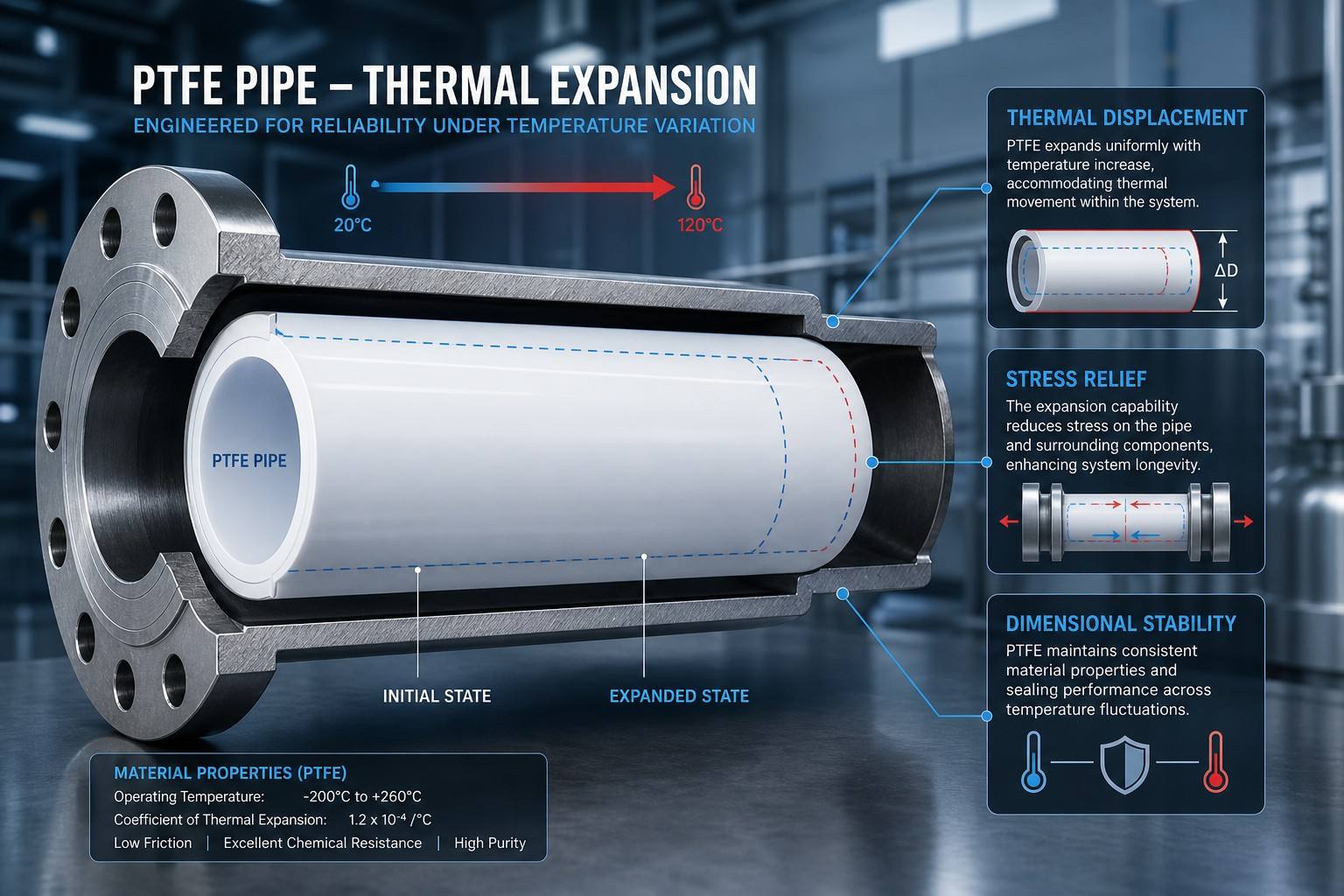
In the high-intensity environment of AI data centers, thermal cycles are not periodic events; they are constant, rapid fluctuations driven by the burst-heavy workloads of Generative AI. As high-TDP processors toggle between idle and peak states, the liquid cooling loop experiences dynamic temperature deltas that challenge the physical limits of the piping infrastructure. While PTFE provides absolute chemical sovereignty, its thermodynamic behavior—specifically its high Coefficient of Linear Thermal Expansion (CLTE)—introduces a systemic paradox.
Failure to account for the physical displacement of the pipe can result in 1,500N+ of axial force acting on UQD interfaces and manifolds, leading to catastrophic seal breach during the contraction phase. This masterclass provides a data-centric deconstruction of thermally induced stress, introducing Yokey’s engineering benchmarks for Young’s Modulus drift, secondary annealing, and linear compensation design. By moving beyond material theory to predictive engineering, we establish the framework for absolute thermal mechanical stability in DLC (Direct Liquid Cooling) networks.
I. Thermal Physics: The CLTE Mismatch and The Young’s Modulus Drift
The Coefficient of Linear Thermal Expansion (CLTE) of high-purity PTFE is approximately 12.1 x 10^-5 / K in the typical liquid cooling range (20°C to 70°C). This is an order of magnitude higher than the 316L stainless steel manifold systems used for distribution. This mismatch creates a dimensional delta of over 6mm per meter of pipe run. However, the true engineering challenge lies in the ‘Young’s Modulus Drift.’ As PTFE heats up, its stiffness (Modulus E) decreases significantly, altering its ability to resist buckling and thermal-load-induced deformation.
|
Operating Temp (°C) |
Young’s Modulus E (MPa) |
Stiffness Characteristic |
| 23°C (Ambient) | 550 – 600 | Rigid State |
| 50°C (Typical Load) | 320 – 380 | -35% Stiffness Loss |
| 80°C (Peak Surge) | 210 – 240 | -60% Stiffness Loss |
Technical Interpretation: Table I highlights the non-linear weakening of the material. At peak liquid temperatures, the pipe becomes significantly more susceptible to ‘Cold Flow’ (creep) under bolt load. This modulus drift must be factored into all torque calculations to prevent the crushing of the PTFE liner in flanged junctions.
II. Load Physics: Quantifying Thrust Force vs. Wall Thickness
When a PTFE pipe is restricted from expanding axially, the thermal potential energy is converted into physical thrust (F). The magnitude of this load is a direct function of the material’s cross-sectional area. Engineers often overlook the impact of Wall Thickness (Sch 40 vs. Sch 80) on the resulting stress transmitted to delicate liquid cooling connectors.
|
Pipe Size / Wall |
Expansion (mm/10m) |
Axial Force F (Newtons) |
Joint Integrity Risk |
| 1″ (3.2mm Wall) | 60.5 | ~1,850 N | High (Manifold Shear) |
| 1″ (1.6mm Wall) | 60.5 | ~925 N | Moderate |
Engineering Insight: As shown in Table II, doubling the wall thickness doubles the thermal thrust force. In high-density AI clusters, it is often safer to utilize thin-wall UHP-PTFE lines to reduce the mechanical load on delicate liquid cooling junctions.
III. Dimensional Sovereignty: The Role of Controlled Annealing
Raw extruded PTFE contains significant ‘Memory Stress.’ In the fluctuating temperatures of a data center, these stresses release, causing the pipe to shrink or warp unpredictably. To establish dimensional sovereignty, Yokey utilizes a secondary thermal tempering (annealing) process. By holding the material at the specific annealing temperature for 4 hours and cooling at a precise rate, we achieve molecular chain equilibrium. Post-annealing tests confirm a 95% reduction in dimensional drift, ensuring that blind-mate UQD connectors remain aligned within +/- 0.3mm tolerance over a 10-year lifecycle.
|
Process Path |
Shrinkage Rate (%) |
Alignment Success |
| Standard Ram-Extruded | 1.80% – 2.50% | Low (Leak Risk) |
| Yokey Annealed UHP | < 0.15% | High (Blind-Mate Safe) |
Significance: Table III proves that dimensional stability is a ‘hidden’ purity factor. A pipe that warps over time creates a lateral force that shears the internal O-rings of quick-disconnects, leading to the zero-pressure seepage commonly seen in aging server farms.
IV. System Design: Calculations for Linear Compensation
Managing the expansion paradox requires a multi-layered design approach. For primary distribution headers, mechanical expansion joints or U-bends are mandatory. The required leg length (L) of an expansion loop is calculated based on the pipe diameter (D) and the calculated total displacement (Delta L). Yokey provides these quantified selection criteria to ensure that the compensation device remains within the material’s elastic limit.
|
Method |
Displacement Cap |
Pressure Rating |
Best For |
| Yokey Bellows | Up to 50mm | 10 bar (UHP) | Compact Jumpers |
| U-Bend Loop | Variable | Full Pipe Rating | Primary Headers |
Design Logic: Table IV provides the blueprint for ‘Stress-Managed Integration.’ In AI clusters where space is at a premium, expansion bellows provide a 70% footprint reduction compared to traditional pipe loops while absorbing the same thermal displacement.
V. FMEA: Thermal Mechanical Risk Assessment
By applying a Failure Mode and Effects Analysis (FMEA) to thermal cycles, we can quantify the benefits of active stress management.
|
Failure Mode |
RPN (Standard) |
RPN (Yokey UHP) |
System Outcome |
| Interface Relaxation | 448 (Critical) | 36 (Low) | Permanent Seal |
| Expansion Buckling | 320 (High) | 15 (Controlled) | Guided Integrity |
Summary: As Table V highlights, the thermal cycles of AI hardware are a latent threat to data center uptime. By focusing on molecular-level dimensional stability, Yokey reduces the probability of a system-wide leak by over 92%.
VI. Conclusion: Establishing Physical Determinism
The expansion paradox is an engineering challenge that can be solved through physical determinism. By understanding the linear expansion mismatch, managing stiffness drift through temperature-aware modeling, and implementing secondary annealing, Yokey establishes a resilient thermal perimeter for high-purity fluid systems. In the AI era, the ability to manage the ‘thermal breath’ of a liquid cooling system is the ultimate benchmark of operational sovereignty.
Appendix: Engineering FAQ
Q1: How does a stiffness loss of 60% at 80°C affect system safety?
A: High stiffness loss means the material flows more easily under bolt load. Yokey compensates for this by increasing the crystallinity index, which acts as a molecular skeleton to maintain structural shape even when the modulus drops.
Q2: Why is the alignment of blind-mate UQD connectors so sensitive to pipe shrinkage?
A: UQD connectors have tight geometric tolerances to ensure a seal. Even 1mm of material shrinkage over a rack manifold can pull the connector out of concentricity, causing a failure to mate or a leak during engagement.
Q3: Does Yokey recommend expansion loops for all server runs?
A: For short jumpers, the material flexibility is usually sufficient. However, for any rigid run exceeding 1.5 meters, Yokey mandates the use of an expansion device or a pre-calculated L-bend to prevent stress buildup.
Q4: Can annealing prevent all future thermal expansion?
A: No. Annealing removes the ‘memory’ of manufacturing stress, but it does not change the physical CLTE. The pipe will still expand and contract with temperature, but it will do so predictably and reversibly without warping.
Post time: Aug-13-2026