
Executive Summary
A server liquid-cooling hose end is a fluid boundary and mechanical connection. Pull-off load may come from maintenance handling, hose weight, bend recovery, vibration, thermal expansion, hose misalignment and pressure thrust. The O-ring or face seal may hold coolant locally, but the hose, fitting, barb, bead, ferrule, clamp, crimp sleeve or connector lock must carry the axial retention function.
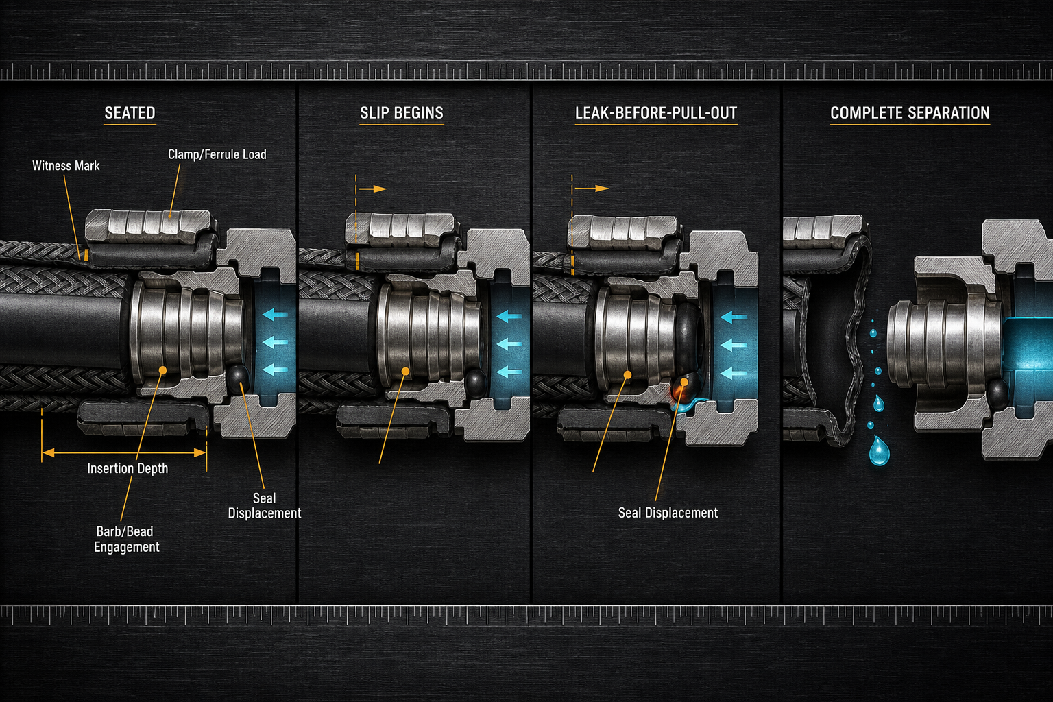
A small axial slip can change seal position and contact pressure before complete separation. Static pressure holding therefore cannot prove reliability under pull-off load, bending, temperature change or repeated reconnection. Evaluation must include leak-before-pull-out, seal movement, separation load and post-maintenance repeatability. Server liquid-cooling hose-end sealing should be evaluated as a combined axial-retention and fluid-sealing interface rather than as a static O-ring joint.
Hose-End Architecture and Load-Bearing Boundaries
In a server liquid-cooling loop, the hose assembly connects the CDU, coolant distribution manifold and cold plate through a hose tube, reinforcement layer, hose-end fitting and service interface. The end may use a barb, retaining bead, shoulder, ferrule, crimp sleeve, clamp, push-to-connect fitting, quick-disconnect coupling, locking collar, retaining clip or secondary retainer. Sealing may occur through an O-ring, face seal, radial seal, end-face seal or conical seal.
Internal pressure creates pressure thrust across the effective fluid area. Pull-off load is transferred through hose-wall friction, barb or bead engagement, ferrule compression, clamp load, crimp geometry or a connector locking function. These features are mechanical retention elements; the seal is not the primary axial load-bearing member. Insertion depth, hose stop contact, shoulder geometry and clamp position define whether both retention length and seal location are adequate.
The coolant pressure boundary, hose-wall retention boundary, seal-contact boundary, fitting-to-hose mechanical boundary, quick-disconnect locking boundary, fitting-body boundary and service boundary must be separated. A radial O-ring may lose compression during slip, a face seal may unload during separation, and a locking collar may appear engaged while the hose end is not fully seated.
Table I: Hose-End Load-Bearing Boundaries and Seal Functions
| Boundary | Load or exposure | Function | Risk | Verification | Limitation |
| Hose wall | Tension and pressure | Carry retention load | Creep or tear | Wall check | Aging dependent |
| Barb or bead | Axial pull | Mechanical engagement | Slip or cut | Imprint review | Needs insertion depth |
| Clamp or ferrule | Radial compression | Hold hose to fitting | Under or over-compress | Position and size | Process sensitive |
| O-ring | Pressure and motion | Local fluid seal | Displacement | Seal inspection | Not main lock |
| Face seal | Axial contact | End-face sealing | Unload under slip | Leak test | Needs seating force |
| Radial seal | Bore contact | Radial pressure seal | Low compression | Groove check | Sensitive to slip |
| Quick-disconnect lock | Service load | Prevent release | Partial lock | Lock verification | Not hose seal proof |
| Service boundary | Maintenance handling | Repeat connection | Reuse damage | Post-service test | Operator dependent |
Sources and Formation of Pull-Off Load
Pull-off load rarely comes from a single deliberate pull. A hose installed too short can carry continuous axial preload from routing tension, hose weight, minimum-bend-radius violation or connector orientation. Bending and torsion convert stored hose strain into axial force at the fitting. Cable-management interference or service tool contact can add side loading that the connector was not designed to carry.
Internal coolant pressure adds pressure thrust, while pump pulsation, valve switching and pressure transients change that thrust over time. Rack or chassis movement, manifold movement, cold-plate movement and CDU vibration can repeatedly stretch the hose end. Thermal expansion and contraction change hose length, stiffness, friction and clamp stress, so the same assembly condition may behave differently after thermal cycling or coolant exposure.
A single maximum pull number cannot represent the full risk. Axial load amplitude, load-rise rate, direction, duration, cycle count, frequency, bending moment, torsional moment, pressure, temperature, hose aging, assembly condition and connector orientation define the damage history. A low-amplitude high-cycle load can produce slip, relaxation or fretting even when one ultimate pull appears acceptable.
Seal Compression, Hose Slip and Pull-Off Failure Mechanisms
Initial insertion depth controls both retention length and seal stability. If the hose does not reach the hose stop or insertion-depth reference, barb engagement, bead engagement and seal placement may all be reduced. Under axial load, hose-wall expansion, contraction, creep or cold flow can reduce frictional retention. The hose may move just enough to shift an O-ring, unload an end-face seal or disturb a radial seal while remaining visually attached.
Ferrule compression, clamp load and barb geometry must be high enough to resist slip but not so high that they cut the hose wall, damage reinforcement or drive the seal into permanent deformation. Uneven clamp compression can create local high stress beside local low retention. Burrs, sharp fitting edges, eccentric grooves and assembly scratches can cut, pinch, roll or twist a seal as the hose end moves.
Leak-before-pull-out is often critical. Evidence may include witness-mark movement, insertion-depth loss, circumferential wetting, intermittent seepage, seal extrusion, pinch marks, ferrule imprint, clamp migration, barb imprint damage, locking-clip displacement, local hose necking, hose-wall tearing, pressure-decay drift and air ingress after cool-down. Complete separation is the terminal retention failure, not the first loss of leak integrity.
Table II: Pull-Off Load Factors and Failure-Risk Matrix
| Factor | Mechanical effect | Seal effect | Failure mode | Control | Limitation |
| Routing tension | Constant axial load | Compression drift | Slip before leak | Length allowance | Route specific |
| Bending load | Side force at end | Uneven contact | Intermittent seepage | Bend-radius control | Hard to isolate |
| Torsion | Twisted hose wall | Seal rolling | Seal damage | Clocking control | Hidden after assembly |
| Pressure thrust | Axial force | Seat unloading | Pull-out under pressure | Pressure-load test | Depends on area |
| Vibration | Micro-motion | Fretting or relaxation | Progressive slip | Support clips | Frequency sensitive |
| Thermal movement | Length and stiffness change | Recompression change | Decay drift | Thermal cycling | Material dependent |
| Maintenance pull | Non-design load | Seal displacement | Leak after service | Tool control | Human variable |
| Partial lock | Low retention | Unstable seal | Sudden release | Lock check | Visual may mislead |
Coolant, Temperature, Hose Aging and Maintenance Interaction
Water-glycol coolant, dielectric coolant, corrosion inhibitors and additives can change the friction and recovery of the hose polymer, seal and fitting contact surfaces. Seal absorption, extraction, swelling, shrinkage, softening, hardening and surface tackiness may alter insertion force, reseating behavior and contact pressure. Hose compatibility must include reinforcement degradation, wall embrittlement, creep and cold flow, not only visible swelling.
Thermal cycling changes hose length, hardness, elasticity and clamp stress. Low-temperature installation can increase stiffness and reduce seating feedback, while high-temperature operation can soften the hose wall and reduce retention margin. A clamp or ferrule that appears correct at assembly may lose effective load after thermal exposure, coolant diffusion or stress relaxation.
Maintenance adds uncontrolled variables. Cleaning agents, lubricants and residual coolant can change insertion friction and holding force. Drain, refill, hose replacement and reconnection can bend or pull the end repeatedly. Metal debris, connector wear debris, crimp fragments and seal particles can raise the seat locally, scratch the seal or contaminate the cooling loop. Root cause should not be assigned only from the final separation position.
Seal Geometry, Retention Hardware and Hose-End Design Selection
Material choices such as EPDM, FKM, FVMQ, NBR, HNBR, silicone, FFKM and PTFE-encapsulated seals must be judged against coolant compatibility, pull-off response, compression-set resistance, stress relaxation, extrusion resistance, friction stability, thermal-cycle response, vibration resistance and serviceability. Coolant compatibility alone does not prove survival under pull-off, vibration and maintenance cycling.
O-rings, quad-rings, face seals, radial seals, profiled seals, molded hose-end seals, bonded seals and flat gaskets carry load differently. Barbed fittings, beaded fittings, ferrule systems, crimp sleeves, worm-drive clamps, constant-tension clamps, spring clamps, push-to-connect fittings, quick-disconnect couplings, locking clips and secondary retainers carry the mechanical retention function. The seal and the retention hardware must not be forced to do the same job.
Clamp compression, crimp length, barb angle, hose wall thickness, surface roughness, edge chamfer and guide geometry determine whether assembly produces stable retention or damage. Over-clamping can cut the hose, crush reinforcement or destabilize the seal; under-clamping can allow slip and pressure-assisted pull-out. Quick-disconnects require separate assessment of lock engagement, internal valve sealing, hose-end sealing and repeat reconnection.
Inspection, Testing and Failure-Analysis Logic
Evidence should be classified as observed, suspected, confirmed, inconclusive or not evaluated. Visual inspection, insertion-mark inspection, magnified seal inspection, fitting-edge review, barb or bead inspection, ferrule and clamp inspection, locking-clip inspection and dimensional checks establish whether the assembly was capable of retention before loading. Measure insertion depth, wall thickness, fitting diameter, seal cross-section, groove depth, concentricity, roughness and hardness where relevant.
Static pressure holding, liquid leakage testing and pressure decay find fluid paths but do not replace axial pull-off testing. Air-ingress testing addresses inward leakage after cool-down and is not equivalent to coolant leakage. A one-time ultimate pull does not represent repeated maintenance. Pull-off testing should record load direction, load-rise rate, hose bend state, internal pressure, temperature, fixture position, insertion depth, displacement and leakage onset, not only maximum load.
Repeated pull-off cycling, proof loading, combined pull-off and pressure testing, combined pull-off and bending testing, vibration, thermal movement, routing verification, clamp-load verification, crimp-dimension verification and quick-disconnect lock verification answer different questions. Disassembly may create new cuts, particles or movement, so retain the failed hose, fitting, clamp or crimp sleeve, seal, coolant, debris and load record. Compare with an unused assembly before assigning mechanism.
Table III: Hose-End Retention and Seal Verification Guide
| Test | Objective | Variable | Detectable issue | Stage | Limitation |
| Coolant immersion | Check compatibility | Medium and time | Swelling or hardening | Material screen | Not pull-off proof |
| Insertion mark | Find hose slip | Mark position | Depth loss | Assembly or field | Needs baseline |
| Clamp or crimp check | Verify retention setup | Diameter and position | Under or over-load | Production | Indirect evidence |
| Static pressure hold | Find fluid path | Pressure state | Liquid leakage | EOL | No axial load |
| Air-ingress test | Find inward path | Low pressure | Air entry | System check | Not coolant leak |
| Pull-off test | Measure retention | Load direction | Slip or separation | Validation | May miss leakage onset |
| Repeated pull-off | Assess service cycles | Cycle history | Retention decay | Reliability | Time consuming |
| Pull-off plus pressure | Combine loads | Pressure and pull | Leak before pull-out | Design validation | Fixture critical |
| Pull-off plus bending | Route realism | Bend radius | Seal shift | System validation | Route specific |
| Vibration test | Micro-motion risk | Frequency and support | Progressive slip | Qualification | Needs field match |
| Lock verification | Check QD state | Latch position | Partial engagement | Service | Not seal proof |
| Failure analysis | Identify mechanism | Surface evidence | Cutting or extrusion | Root cause | Disassembly can alter |
Assembly, Maintenance and Long-Term Reliability
Long-term reliability begins with hose-length allowance, routing clearance, bend-radius control, strain relief, support clips and alignment. Interface mismatch should not be corrected by forcing the hose to bend. Insertion-depth marking provides a witness for axial slip during operation or service, even before continuous leakage.
Assembly control should include chamfer inspection, deburring, lubricant control, clamp positioning, clamp orientation, crimp-process control, ferrule inspection, locking-clip engagement, secondary retention and coupling verification. After coolant refill and air removal, retention, liquid leakage, pressure decay and air ingress must be verified separately. Seal reuse should not rely only on appearance.
Traceability should link hose, fitting, seal, clamp or ferrule, coolant batch, maintenance record and test result. Service documentation should define insertion marks, allowable bend paths and replacement criteria. Any change in hose material, fitting geometry, clamp, crimp process, quick-disconnect design or routing should trigger renewed combined pull-off and leak verification.
FMEA Risk Analysis: Server Liquid-Cooling Hose-End Sealing Under Pull-Off Load
Hose routing, pressure thrust, bending, vibration, thermal displacement and maintenance handling can all create pull-off load. That load is transferred through the hose wall, barb, bead, clamp, ferrule, crimp sleeve or lock before it changes seal compression, contact pressure and axial seal position. Leakage may result from extrusion, rolling, twisting, pinching, cutting, compression set or material change. The RPN values are illustrative engineering risk rankings, not field statistics or experimental results. Static pressure holding cannot prove mechanical retention or seal reliability under pull-off load.
Table IV: FMEA Risk Analysis
| Failure mode | Cause | Local effect | System effect | Detection | RPN | Action |
| Insufficient insertion depth | Assembly error | Short engagement | Slip and leak | Witness mark | 190 | Use stop and mark |
| Sharp edge or burr | Poor finishing | Seal cutting | Coolant seepage | Edge inspection | 168 | Deburr and chamfer |
| Hose-wall damage | Bad preparation | Weak wall | Pull-out risk | End inspection | 160 | Control cutting process |
| Hose creep or cold flow | Load and heat | Retention loss | Pressure-decay drift | Dimensional check | 172 | Validate material and clamp |
| Low barb or bead engagement | Wrong depth or geometry | Low holding force | Separation risk | Imprint review | 184 | Revise geometry |
| Ferrule under-crimp | Process variation | Low compression | Hose slip | Crimp dimension | 176 | Tighten crimp control |
| Ferrule over-crimp | Excess compression | Hose or seal damage | Early leakage | Teardown | 164 | Reduce crimp severity |
| Clamp migration | Vibration or creep | Load shift | Leak after cycles | Position check | 150 | Add locator or retainer |
| Partial QD lock | Incomplete engagement | Low retention | Service interruption | Lock check | 188 | Add positive verification |
| Low seal compression | Slip or tolerance | Microchannel | Leak or air ingress | Leak and decay test | 180 | Control stack-up |
| Seal extrusion or cutting | Gap or edge damage | Seal loss | Coolant leak | Magnified inspection | 170 | Support and chamfer |
| Coolant swelling or shrinkage | Medium mismatch | Size and friction drift | Unstable sealing | Immersion test | 152 | Validate coolant pair |
| Pressure-thrust overload | Pressure transient | Axial movement | Pull-out under pressure | Combined test | 186 | Add retention margin |
| Bend-radius violation | Routing error | Side load | Leak-before-pull-out | Route audit | 166 | Add strain relief |
| Particle entrapment | Debris ingress | Local seat gap | Intermittent seepage | Debris analysis | 144 | Improve cleanliness |
| Inadequate pull-off validation | Static-only release | Hidden risk | False confidence | Test-plan audit | 196 | Add combined cycling |
Conclusion
Server liquid-cooling hose-end seals face a combined environment of axial pull, pressure thrust, bending, torsion, vibration, temperature change and maintenance load. Hose retention and seal retention are different but linked problems. Insertion depth, barb or bead engagement, clamp or crimp structure, quick-disconnect locking, fitting stiffness and seal compression must therefore be assessed together.
A slight hose slip can produce coolant seepage, pressure-decay drift or air ingress before complete separation. Static pressure holding, one-time ultimate pull-off and post-maintenance leak testing are not interchangeable. A hose-end structure not validated under combined pull-off, pressure, bending, temperature and maintenance cycling should not be claimed reliable for long-term server liquid-cooling service.
Engineering FAQ
Q:Why can hose routing affect the pull-off load of a server liquid-cooling hose assembly?
A:Routing defines whether the hose reaches the connector neutrally or with stored tension. A short hose, tight bend or unsupported span can add axial load, bending moment and torsion before pressure is applied. Insertion depth, barb engagement, clamp or crimp load and lock engagement then determine whether that load becomes slip. Static pressure alone will not reveal routing-induced pull-off risk.
Q:How is hose retention different from seal retention?
A:Hose retention is the mechanical resistance provided by friction, barb or bead engagement, clamp force, crimp geometry or a coupling lock. Seal retention is the ability of the O-ring, face seal or radial seal to remain seated and compressed. A hose can remain attached while the seal has shifted. Leakage, air ingress and complete pull-out must be evaluated separately.
Q:Can a hose begin to leak before it completely pulls out of the fitting?
A:Yes. Leak-before-pull-out occurs when axial slip changes seal location or contact pressure before the hose leaves the fitting. Witness-mark movement, circumferential wetting, pressure-decay drift or intermittent seepage may appear first. Temperature, vibration, particles and coolant swelling can accelerate the transition. A pass on static pressure does not prove the seal remains stable during pull-off.
Q:How does internal coolant pressure contribute to hose-end pull-off load?
A:Internal pressure creates axial pressure thrust across the effective fluid area and can add to manual, routing or vibration loads. The resulting force is carried mainly by the hose wall, barb, bead, clamp, ferrule, crimp sleeve or lock, not by the seal alone. Liquid leakage and air ingress still need separate tests because pressure direction and temperature history change the path.
Q:Why can bending and torsion be as important as direct axial pulling?
A:Bending and torsion create local hose-wall distortion, uneven clamp contact and skewed seal compression. They may also move the insertion mark without a clean straight pull. A connector that survives direct axial loading can still leak under combined bending, pressure and vibration. Verification should reproduce hose route, bend radius, temperature state and maintenance handling rather than only straight pull.
Q:Which tests are useful for confirming pull-off-related seal failure?
A:Useful methods include insertion-depth inspection, clamp or crimp verification, pressure decay, liquid leakage, air-ingress testing, pull-off testing, repeated pull-off cycling, combined pull-off with pressure or bending, vibration, thermal movement, lock verification and failure-surface analysis. Each answers a mechanism question. One static pressure hold cannot confirm long-term reliability.
Q:How should a liquid-cooling hose end be inspected after maintenance or reconnection?
A:After service, check the insertion mark, hose stop contact, clamp or ferrule position, lock engagement, seal condition, fitting edge, particles, residue and routing strain. Then verify liquid leakage, pressure decay, air ingress and retention separately. Appearance-only reuse can miss cutting, cold flow, compression set or reinforcement damage.
Post time: Sep-09-2026