
Executive Summary: What Should an Engineer Determine After Pulsation?
For design, maintenance, reliability and failure-analysis engineers, the practical question is not whether a rotor pump shows pulsation, but whether the pulsation is changing the local face-seal condition and contributing to leakage, friction, heat or wear. Periodic displacement, pressure and velocity changes may alter face-closing and face-opening forces. The interface film may then be replenished, expelled, thinned, redistributed or locally interrupted, depending on the actual pump and seal configuration.
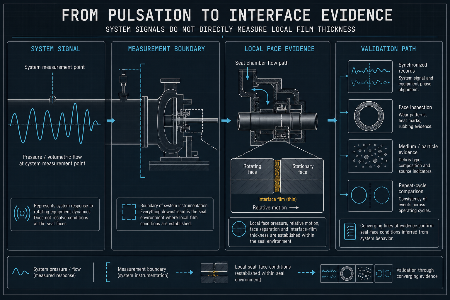
This chain is conditional. Pulsating flow does not by itself prove face opening, dry running, cavitation or seal failure. A system pressure or flow signal does not directly measure local face pressure, relative face motion, face separation or film thickness. The core judgment therefore requires more than one signal: compare the event timing with the actual face-seal arrangement, operating state, medium, surfaces, secondary seals and local evidence.
A defensible review combines synchronized pressure, flow, speed, temperature, displacement and leakage records with face, secondary-seal, surface, medium, particle and maintenance evidence. Prepare the pump and seal structure, measurement locations, operating history and inspection records before choosing corrective action. This article provides a path to identify possible film changes, separate them from competing causes, validate the represented configuration, control recurrence and determine when a configuration-specific technical review is appropriate.
Rotor-Pump and Face-Seal Interface Architecture
The relevant system boundary includes the rotor assembly, pump chamber, pressure zones, shaft, face-seal pair, closing mechanism, secondary seals and adjacent flow paths. The actual arrangement may be single or dual, internal or external, balanced or unbalanced, with different stationary and rotating components. Because those details are not confirmed here, the discussion describes a class of interfaces rather than one specific pump design.
The first design question is how pressure reaches each side and how closing force is generated. Hydraulic loading, spring or bellows response, shaft movement, thermal expansion, runout, misalignment and associated friction may affect the interface. Assembled clearance, face condition, secondary-seal fit and operating position matter more than the nominal drawing.
The second question is how the medium reaches, supports and leaves the faces. A film may be process medium, lubricant or another layer; its composition and load-bearing behavior require confirmation. Flow access does not prove stable film or uniform contact, so orientation, pressure field and heat removal must be considered together.
Table 1 – Rotor-Pump Face-Seal Features That Influence Film Stability
| Structural or Operating Feature | Possible Film / Load Mechanism | Face-Seal Response | Potential Risk | Recommended Check |
| Pressure zones around the face pair | Changes hydraulic opening or closing contribution | Contact distribution may shift | Local film thinning or intermittent leakage | Review pressure locations and synchronize with motion |
| Closing mechanism and axial movement | Changes normal load during movement | Face gap or contact ratio may vary | Friction drift, wear or heat | Inspect mechanism, displacement and preload evidence |
| Face geometry and surface condition | Controls local contact and film support | Stable or uneven interface response | Scoring, transfer or localized leakage | Check flatness, surface condition and wear maps |
| Secondary-seal fit and friction | Restricts or delays axial response | Transient load may be altered | Stick-slip or delayed reseating | Inspect fit, movement and material condition |
Pulsating Flow and Face-Seal Load Balance
Rotor-pump pulsation can arise from periodic displacement, rotor geometry, restrictions, trapped gas, system compliance, valve response or another hydraulic interaction. Pressure, flow, velocity and speed variations are related but not interchangeable; their phase, location and waveform determine whether the face seal experiences a meaningful load change.
Pressure may modify hydraulic force, velocity may change shear, replenishment and heat removal, and speed may change sliding and heat even at steady average pressure. Repeated variation may change face gap, contact ratio or local pressure distribution; tilt, axial displacement or secondary-seal friction can make the response asymmetric.
Correlation is not proof. A system or volumetric pressure/flow waveform may precede temperature, leakage or displacement changes, but it does not directly measure pressure at the faces, relative face motion, face separation or film thickness. Pump, pipework and seal-chamber dynamics may attenuate, delay or phase-shift the waveform. Local inspection, suitable motion or thermal evidence and repeatability remain necessary.
Table 2 – Pulsation Mechanisms and Evidence Requirements
| Suspected Mechanism | Observable Signal or Condition | Possible Interface-Film Effect | Required Confirmation | Interpretation Boundary |
| Periodic pump displacement | Repeatable pressure or flow variation linked to rotor position | Periodic load and replenishment change | Position, pressure, flow and leakage timing | Correlation does not establish film thickness |
| System restriction or compliance | Pressure response differs by location | Local load phase may differ from pump signal | Multi-point pressure and flow measurement | One sensor may miss the seal condition |
| Gas or intermittent filling | Irregular pressure, flow or vibration response | Film continuity and heat removal may be disturbed | Gas-state evidence, operating review and inspection | Do not label as cavitation without evidence |
| Speed or control variation | Change in speed, displacement or torque response | Sliding and thermal response may change | Speed, motion, temperature and leakage records | Speed change alone does not prove face opening |
Interface-Film Formation, Redistribution and Loss
The interface film is dynamic: formation depends on medium, surfaces, relative motion, pressure and replenishment. It may enter, redistribute or leave the interface as heat and shear change; recovery requires renewed supply and suitable separation. Thinning is not complete rupture, and local interruption may recover when pressure, speed or supply changes.
Temperature, friction, leakage, face marks, transfer or particles may support a film-loss hypothesis, but may also reflect alignment, secondary-seal, assembly, pump or maintenance causes. A defensible conclusion connects a time-resolved event to local evidence and a repeatable consequence; otherwise state only that pulsation may have contributed to film instability or changed contact.
Operating Variables, Friction, Wear and Leakage Pathways
Viscosity, particles, gas, temperature, pressure and speed can affect replenishment, shear, heat removal, loading and sliding; start, stop, reverse and dry-running transients are not represented by steady data. Flatness, roughness, waviness, alignment, axial movement and secondary-seal friction also determine contact uniformity. Compare any contact mark, deposit, discoloration, crack or particle field with motion direction, pressure side and assembly history.
System pressure and volumetric flow signals describe their measurement locations. Pipe compliance, restrictions, gas content, leakage paths and seal-chamber geometry may alter amplitude, timing and phase before a condition reaches the face pair. Leakage may be intermittent, stable, internal or external; neither a synchronized event nor a persistent leak identifies film loss without excluding competing causes.
Table 3 – Operating Variables and Face-Seal Response
| Operating Variable | Possible Influence on Pulsation or Load | Possible Film / Friction Response | Risk Indicator | Verification Method |
| Pressure and pressure difference | Changes hydraulic force balance | Local contact or gap may vary | Leakage or temperature linked to pressure phase | Time-aligned pressure, motion and leakage records |
| Flow and velocity | Changes replenishment, shear and heat removal | Film redistribution or thinning | Thermal or friction response | Flow measurement with local interface evidence |
| Speed and operating cycle | Changes sliding rate and transient response | Friction and heat may drift | Wear or leakage after cycling | Repeat-cycle testing and face inspection |
| Temperature | Changes viscosity, material response and clearance | Film support or recovery may change | Progressive thermal or leakage drift | Temperature trend with medium and seal evidence |
| Process medium and viscosity | Changes replenishment, shear and drainage | Film supply or load support may vary | Thermal, friction or leakage drift after medium change | Confirm medium, temperature and local interface evidence |
| Gas content or intermittent filling | Interrupts liquid continuity and heat removal | Film continuity may become irregular | Irregular leakage, temperature or vibration response | Review filling state, gas evidence and synchronized records |
| Particles or contamination | Introduces abrasive or obstructive material | Scratching, transfer or local film interruption | Progressive wear or particle-linked leakage | Analyze particles and inspect faces, chamber and flow path |
| Alignment, runout and axial movement | Changes face tracking and local opening or closing | Uneven contact or periodic separation may occur | Localized wear, temperature or leakage pattern | Measure motion, runout and face condition against phase |
| Secondary-seal friction | Restricts or delays axial response | Stick-slip or delayed face recovery may occur | Hysteresis, unstable contact or reseating drift | Assess movement, fit, friction evidence and material state |
Characterization and Evidence Limits
Characterization begins with the assembled interface. Record face-seal arrangement, pressure zones, closing mechanism, axial movement, runout, alignment, surfaces, secondary-seal fit, flow path and heat-removal route. Identify sensor locations and measurement boundaries, compare new, operated and post-maintenance states, and synchronize pressure, flow, speed, temperature, displacement and leakage or functional signals through relevant transients. These records establish timing at measured locations, not direct film thickness or local face state.
Use face inspection, surface mapping, medium or particle analysis and thermal or friction response where available. Record scoring, transfer, deposits, particles, cracks, discoloration, uneven contact and secondary-seal condition against a controlled reference. Pressure characterizes an event, leakage quantifies a defined condition and visual inspection records marks; none alone proves contact pressure, mechanism or film history.
Validation Path for Pulsating-Flow Face-Seal Film Changes
1. Architecture and Face-Seal Geometry — Confirm the actual face-seal arrangement, pressure boundary, closing mechanism, face geometry, secondary seals, surfaces and assembly state. This establishes the mechanical boundary, but does not alone prove film stability.
2. Pulsation and Load Characterization — Synchronize pressure, flow, speed, temperature, displacement and leakage or functional signals, identifying each measurement location. This establishes timing and correlation at those locations, but does not directly prove local face pressure, relative face motion, face separation, film thickness or rupture.
3. Interface and Material Response — Combine thermal or friction response, face inspection, particle or medium evidence and material condition. This supports mechanism discrimination, but one appearance cannot determine film history.
4. Leakage and Functional Evidence — Apply a defined leakage, temperature, friction or functional assessment. A single static result cannot represent all dynamic pulsation states.
5. Repeatability and Change Control — Repeat the operating sequence and reassess after changes to medium, speed, pressure, temperature, alignment, face components, secondary seals or maintenance. Conclusions apply only to the represented configuration.
Engineering Controls and Maintenance Strategy
The first control layer is structure and interface: control face geometry, surfaces, alignment, axial movement, runout, closing-force path, secondary-seal fit, cleanliness, flow and heat removal; specific limits require design and test data.
The second is material and medium compatibility. Evaluate face materials, secondary-seal compound, medium, particles, gas, temperature, pressure and film condition together; a material name alone does not establish film stability.
The third is operating and maintenance discipline. Trend relevant signals, define responses to abnormal pulsation and transients, set teardown and replacement criteria, and revalidate changes affecting load, film supply, alignment, surfaces or heat removal. Controls should link a suspected cause to a discriminating measurement.
FMEA Risk Analysis
This qualitative FMEA does not assign an RPN. Risk depends on pump architecture, face-seal design, medium, operating condition, pulsation, maintenance and leakage or contamination consequence.
Table 4 – FMEA for Pulsating-Flow Face-Seal Film and Leakage Risk
| Failure Mode | Cause | Local Effect | System Effect | Detection Method | Control Action |
| Face load changes with pulsation | Upstream restriction, compliance or periodic displacement changes the measured pressure/flow condition | Contact distribution may shift | Intermittent leakage or wear | Multi-point pressure/flow, motion and leakage records | Characterize the load path and measurement boundaries |
| Interface film becomes locally thin or interrupted | Insufficient replenishment, gas interruption or transient face separation | Friction or heat response changes | Face damage or leakage pathway | Thermal, friction, face and medium evidence | Control flow path and validate repeatability |
| Face scoring or transfer | Particles, poor alignment or film loss | Surface roughness and local damage | Persistent or progressive leakage | Teardown and surface inspection | Control cleanliness, alignment and particles |
| Secondary-seal response changes | Material change, friction or ageing | Delayed or uneven axial movement | Unstable contact response | Fit, movement and material assessment | Verify compatibility and assembly condition |
| Pulsation cause is misattributed | System pressure, flow or temperature signal treated as local face evidence | Incorrect mechanism assigned | Unresolved leakage or repeat failure | Review sensor locations, phase and local evidence | Use synchronized system records with interface inspection |
| Post-maintenance seal condition changes | Alignment, surface or cleanliness change | New contact or film behavior | Changed leakage state | Pre/post-maintenance comparison | Controlled assembly and change verification |
How Yokey Supports Configuration-Specific Face-Seal Evaluation
Yokey can support a configuration-specific review of rotor-pump face-seal questions using the pump and seal arrangement, measurement locations, operating records, medium, gas or particle information, face and secondary-seal inspection, leakage, thermal or friction evidence and maintenance history. The purpose is to distinguish pulsation-related film or contact changes from alignment, surface, material, gas, particles, assembly or maintenance factors and identify the next validation direction.
This review does not establish universal material, dimension, film thickness, pressure, temperature, life, leakage, friction or thermal results. Conclusions require the actual configuration and evidence. Provide the pump and seal structure, seal function, measurement locations, operating records, medium information and inspection evidence.
Conclusion
Pulsating flow may change the pressure and velocity environment at a rotor-pump face seal, altering hydraulic load balance, relative movement and interface-film formation, replenishment, thinning or redistribution. Friction, heat, wear and leakage cannot be assigned to pulsation alone without configuration-specific records and local evidence. Control requires joint assessment of architecture, geometry, medium, operating sequence, surfaces, secondary seals, monitoring, maintenance and repeatability after change.
FAQ: Rotor-Pump Face-Seal Pulsation and Interface Film
These questions address design, diagnosis and validation when a rotor pump shows pulsating operation or changing face-seal behavior. Conclusions depend on the pump, seal, medium, operating state and evidence.
Q:What is interface-film change in a rotor-pump face seal?
A:It is a change in formation, supply, thickness, distribution, continuity or load-bearing behavior of the layer between seal faces. Without a suitable method, it is a condition to investigate, not a confirmed measurement.
Q:How can pulsating flow affect face-seal contact?
A:Pressure and velocity variation may change hydraulic loading, replenishment, shear, heat removal and relative movement. Response depends on pressure boundaries, geometry, closing force, alignment, medium and phase.
Q:Is pressure pulsation the same as face-seal film loss?
A:No. Pressure pulsation is a system signal or condition. Film loss is an interface mechanism. A relationship must be supported by synchronized timing, local face or material evidence and a repeatable consequence.
Q:Can an interface-film change increase friction or wear?
A:It can if reduced separation increases solid interaction. Alignment, particles, material change, surface damage or secondary-seal friction can produce the same response; competing causes require assessment.
Q:Can pulsating flow cause face-seal leakage?
A:It may contribute by changing face load or film stability, but damage, assembly, material, alignment, pressure boundary or maintenance can also cause leakage. Leakage alone does not identify cause.
Q:Which signals should be recorded during validation?
A:Record relevant pressure, flow, speed, temperature, displacement and leakage or functional signals on a common time base, with location, event definition and interpretation limits documented.
Q:How can film loss be distinguished from alignment or material problems?
A:Use synchronized operating data with face inspection, surface mapping, secondary-seal assessment, medium or particle analysis and controlled comparisons. No single pressure, temperature or visual result is sufficient.
Q:When should a rotor-pump face seal be inspected or revalidated?
A:Inspect or revalidate after changes in leakage, temperature, friction, vibration, pulsation, face condition, medium, speed, pressure, alignment, seal components or maintenance. Base the trigger and scope on the configuration and evidence.
Post time: Sep-27-2026