
Revision status: Revised technical article for international website publication. Project-specific pump curves, coolant data and test records remain mandatory for final design decisions.
|
Web publication field |
Recommended value |
| Primary keyword | liquid cooling CDU pump reliability |
| Suggested title tag | Pump Reliability in Liquid Cooling CDUs: Cavitation, NPSHa and NPSHr |
| Suggested meta description | A practical engineering guide to preventing CDU pump cavitation by comparing NPSHa and NPSHr under temperature, filter loading, low-level and transient conditions. |
| Suggested URL slug | pump-reliability-cavitation-npsh-liquid-cooling-cdus |
| Audience | Liquid cooling designers, pump selection engineers, commissioning teams, data center operators and technical decision-makers |
Executive Summary
A coolant distribution unit (CDU) pump requires a stable liquid supply at its inlet. Cavitation occurs when local liquid pressure falls below the coolant vapor pressure at the operating temperature. In a CDU, the pump is only one part of the risk. Inlet pipe geometry, filter loading, valve position, reservoir level, gas release, venting, speed and rapid load changes determine whether the inlet condition remains acceptable.
The engineering comparison is net positive suction head available (NPSHa) versus net positive suction head required (NPSHr). NPSHa is created by the installed system. NPSHr is specific to the selected pump, speed, flow, test method and stated performance criterion. The comparison must use absolute pressure and the actual coolant properties at the limiting temperature, flow, liquid level, filter condition and transient event.
This article separates cavitation from air entrainment, dissolved-gas release and flashing. These conditions can all create bubbles and unstable operation, but their causes and corrective actions differ. The recommendations below are general engineering guidance; they do not replace the selected pump manufacturer’s curve, the project calculation, or commissioning validation.
Cavitation Physics in Liquid Cooling Pumps
When local static pressure falls below the coolant saturation vapor pressure, vapor bubbles form. When those bubbles enter a higher-pressure region, they can collapse and generate pressure pulses. Repeated collapse may cause impeller pitting, noise, vibration, head and flow loss, and reduced mechanical-seal life. Bearing distress can occur as an indirect consequence of vibration and hydraulic instability, but it is not a unique cavitation signature.
Air entrainment introduces external gas through a vortex, poor venting, leakage or reservoir geometry. Dissolved-gas release occurs when gas leaves the liquid after a pressure or temperature change. Flashing persists when downstream pressure remains below the liquid vapor pressure. Bubbles in a transparent section do not identify the mechanism by themselves; pressure, temperature, liquid level, gas condition and pump data must be correlated.
Diagnostic map: cavitation causes and early warning signals
|
Risk source |
Physical mechanism |
Early signal |
Affected component |
Recommended check |
| Low inlet pressure | Pressure approaches vapor pressure | Noise, vibration or unstable pressure | Impeller and inlet | Measure absolute inlet pressure and temperature |
| High coolant temperature | Vapor pressure rises | Risk appears at peak thermal load | Pump inlet | Use actual coolant property data |
| Filter loading | Inlet loss increases | Rising differential pressure | Pump inlet | Trend filter differential pressure at known flow |
| Inlet valve restriction | Suction head decreases | Flow loss or fluctuation | Pump inlet | Verify position and pressure response |
| Low reservoir level | Static head or inlet coverage falls | Air ingestion or vortexing | Inlet and impeller | Check minimum level, coverage and venting |
| Gas or rapid flow change | Inlet feed becomes unstable | Irregular noise or short event | Pump and controls | Review priming and synchronized transient data |
This table is a diagnostic map, not a universal alarm specification. A pump should not be classified as cavitating until inlet pressure, temperature, level, gas condition, filter state and operating point have been reviewed together.
NPSHa versus NPSHr: Definitions and Calculation Boundary
NPSHa is a system property. At the defined pump reference location, a screening form is:
NPSHa = (P_abs – P_vap) / (rho x g) + V^2 / (2g)
where P_abs is the absolute pressure at the reference location, P_vap is the coolant vapor pressure at the stated temperature, rho is the coolant density, g is gravitational acceleration and V is the local liquid velocity. In a tank-to-pump system calculation, the pressure head, elevation head and inlet-side losses must be referenced to the same datum and treated consistently.
Gauge pressure must not replace absolute pressure. The calculation record should identify the reference location, pressure measurement method, fluid density, vapor pressure, viscosity, liquid temperature, elevation, velocity head and every inlet-side loss included. For glycol-water or dielectric coolants, do not substitute pure-water properties without a documented engineering basis.
NPSHr is pump-specific. It changes with pump geometry, speed, flow, operating point, test method and the stated performance criterion. Common pump test terminology uses NPSH3 for the NPSH at which first-stage total head has fallen by 3% because of cavitation. Therefore, NPSH3 is not a zero-cavitation boundary. The pump curve must state the test medium, temperature, speed, flow, measurement location and criterion.
The 2024 ANSI/HI 9.6.1 guidance distinguishes the manufacturer-supplied NPSHR used for margin evaluation from NPSH3. The project should state which edition, definition and margin basis it uses. No fixed pressure threshold or margin is universal for every CDU.
NPSH risk factor matrix
|
Risk factor |
Effect on NPSH comparison |
Trigger |
Measurement point |
Response |
| Coolant temperature | Higher vapor pressure reduces margin | Peak thermal load | Pump inlet | Check worst-case coolant data |
| Reservoir level | Lower level reduces static head | Low fill, drain or service | Tank and inlet | Define minimum operating level |
| Inlet pressure | Lower pressure reduces NPSHa | Restriction or low head | Pump inlet tap | Investigate the complete inlet path |
| Filter differential pressure | Higher loss reduces NPSHa | Element loading or bypass | Across filter | Trend dP with bypass status and flow |
| Inlet resistance | Loss grows with flow and geometry | Long or complex path | Inlet pressure points | Simplify path or resize components |
| Gas condition | Destabilizes inlet feed; separate from vapor-pressure calculation | Poor venting or pressure change | Vent or reservoir | Improve venting and priming |
| Speed and flow | Can increase losses and NPSHr | Fast load or speed change | Speed, flow and pressure | Rate commands and test transients |
Illustrative CDU screening example
The following numbers are illustrative only and are not a CDU design limit. Replace every value with project data before use. Assume a closed CDU loop with a coolant density of 1,030 kg/m3, tank absolute pressure of 101.3 kPa, coolant vapor pressure of 12.0 kPa at the limiting temperature, 0.80 m static head above the pump reference and 1.25 m total inlet-side loss including the loaded filter. The screening result is:
NPSHa = (101.3 – 12.0) x 1000 / (1,030 x 9.81) + 0.80 – 1.25 = approximately 8.4 m
If the selected pump manufacturer states NPSHr = 2.4 m at the required flow and speed under the stated test condition, the comparison is favourable for this illustrative steady case. The calculation must then be repeated for low level, maximum temperature, filter loading, startup priming and rapid speed or load changes. A steady result cannot validate a transient condition.
System Design and Operating Risk
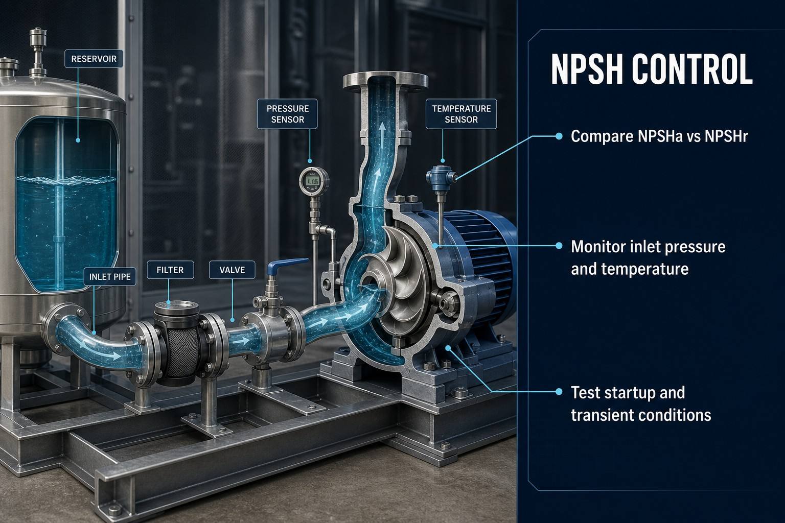
Keep the pump inlet short, direct and free of avoidable restrictions. Diameter, bends, reducers, fittings, filter location and valve position influence inlet loss. A partly closed inlet valve can create a severe restriction even when the control command appears normal; verify position through feedback or pressure response.
An upstream filter protects the loop but can become an NPSH risk when loaded. Establish a clean-element baseline, monitor differential pressure and define maintenance using actual flow and bypass condition. A finer element is not automatically safer if it creates excessive suction loss or causes bypass activation. If the differential pressure plateaus, check bypass status rather than assuming the filter has stopped loading.
The reservoir or expansion tank must maintain liquid coverage during fill, drain, thermal and service conditions. High points require controlled venting, while low points require controlled drainage. Incomplete priming, trapped air and vortex formation can mimic or trigger cavitation. Use staged startup and controlled shutdown where required. Test rapid speed changes with inlet and outlet pressure, flow, temperature, level and speed recorded on a common time base.
CDU pump installation and operating checks
|
Item |
Check |
Consequence |
Confirmation |
Phase |
| Inlet pipe | Short, direct and adequately sized | NPSHa loss | Drawing and pressure review | Design |
| Inlet valve | Fully open and secured | Local suction loss | Position and pressure response | Commissioning |
| Inlet filter | Capacity, clean baseline and bypass logic | Progressive restriction | Differential-pressure trend | Operation |
| Reservoir or tank | Minimum level and inlet coverage | Air ingestion or low head | Level and visual check | Design and operation |
| High-point vent | Gas removal path available | Unstable flow | Venting and priming test | Commissioning |
| Priming | Pump and inlet fully filled | Dry running or vapormation | Procedure and status check | Startup |
| Speed control | Startup, shutdown and ramps controlled | Transient cavitation | Synchronized pressure and flow | Controls |
Detection, Testing and Maintenance
Early signs may include broadband or high-frequency acoustic changes, abnormal vibration, unstable flow, reduced head, pressure fluctuation and performance changes linked to temperature or speed. None of these signs is diagnostic in isolation. Impeller pitting, erosion, bearing distress and seal damage may also result from air, imbalance, misalignment, corrosion or foreign material.
Verification should combine the NPSHa/NPSHr review, inlet and outlet pressure records, flow-head comparison, vibration and acoustic monitoring, temperature and level trends, filter differential pressure, and startup, shutdown and maximum-load transient tests. After a suspected event, correct the inlet condition before replacing the pump. Inspect wear surfaces, repeat pressure and flow checks, confirm priming and venting, and perform a controlled restart.
Recommended commissioning record
Cavitation FMEA: Failure Modes, Effects and Action Priority
The table below separates failure modes from local effects and system effects. The RPN values are illustrative project examples only; they are not universal limits and must not be used without a documented Severity, Occurrence and Detection scale. Where the project follows AIAG & VDA FMEA, use the applicable Action Priority method in addition to, or instead of, a simple RPN ranking.
|
Failure mode |
Cause |
Local effect |
System effect |
Detection |
Illustrative RPN |
Action |
| Insufficient NPSHa | Low pressure or high inlet loss | Vapor formation risk | Flow and head loss | Absolute pressure and temperature | 160 | Correct inlet and verify |
| Filter blockage | Element loading | Suction loss | Cooling reduction | Filter differential pressure and bypass status | 126 | Maintain and review capacity |
| Low reservoir level | Drain or poor level control | Low head or vortex | Gas ingestion | Level and visual check | 120 | Restore level and interlock |
| Air entrainment | Poor venting, leak or vortex | Gas at inlet | Noise and instability | Acoustic, pressure and vent data | 140 | Improve venting and priming |
| Incomplete priming | Startup procedure or trapped air | Heat and wear | Pump damage | Level, flow and motor status | 180 | Prove liquid presence |
| Inlet valve restriction | Valve partly closed or failed feedback | Local pressure loss | Reduced margin | Position and pressure response | 144 | Lock, prove and test valve |
| Excessive temperature | High load or control fault | Higher vapor pressure | Reduced NPSHa | Temperature and pressure | 135 | Control and reassess |
| Transient inlet starvation | Fast speed or load change | Temporary low inlet pressure | Intermittent cavitation | Time-synchronized trend | 147 | Rate commands and test |
Impeller erosion and cooling flow loss are treated here as consequences or system effects, not as primary failure modes. High-priority actions should become level interlocks, filter alarms, valve proof checks, priming verification, speed limits and transient test records.
Engineering FAQ
Q:What is the difference between NPSHa and NPSHr?
A:NPSHa is the suction condition created by the installed system at a defined pump reference location. NPSHr is the pump-specific requirement at a stated speed, flow, test medium and performance criterion. Compare them using absolute pressure, actual coolant properties, the selected pump curve and the limiting system condition.
Q:Does NPSHr mean that the pump is free from cavitation?
A:No. Common NPSH3 terminology identifies the NPSH at which first-stage total head has fallen by 3% because of cavitation. The project margin basis must follow the selected standard, pump manufacturer data and the required reliability objective.
Q:How can cavitation be distinguished from air entrainment?
A:Cavitation is caused by local pressure falling below liquid vapor pressure. Air entrainment introduces gas through a vortex, poor venting, leakage or reservoir conditions. Check pressure, temperature, level, venting, bubble behaviour and operating data together; noise alone is not diagnostic.
Q:Why does coolant temperature affect cavitation risk?
A:As temperature rises, vapor pressure generally rises, reducing the pressure head above vapor pressure. The magnitude depends on the actual coolant formulation. Use the project coolant TDS or validated property data, not an unqualified pure-water assumption.
Q:How should a CDU pump be verified after a suspected cavitation event?
A:Correct the inlet condition, inspect the impeller and wear surfaces, review synchronized pressure and flow records, repeat the NPSHa/NPSHr check, confirm priming and venting, and perform a controlled startup while monitoring pressure, flow, temperature, vibration and alarms.
Conclusion
CDU pump reliability depends on the combined condition of the pump inlet, coolant state, reservoir, filter, valves, layout and transient controls. NPSH management must be included in liquid cooling design, commissioning, monitoring and maintenance. Replacing the pump without correcting the inlet condition only transfers the same failure mechanism to the next component.
For an engineering review, provide the pump curve, coolant data, flow rate, temperature range, reservoir conditions and system layout. These inputs allow the NPSHa/NPSHr calculation and commissioning test plan to be checked against the actual operating envelope.
Post time: Aug-17-2026