
Executive Summary: Why Immediate Leak-Free Results Are Not Enough
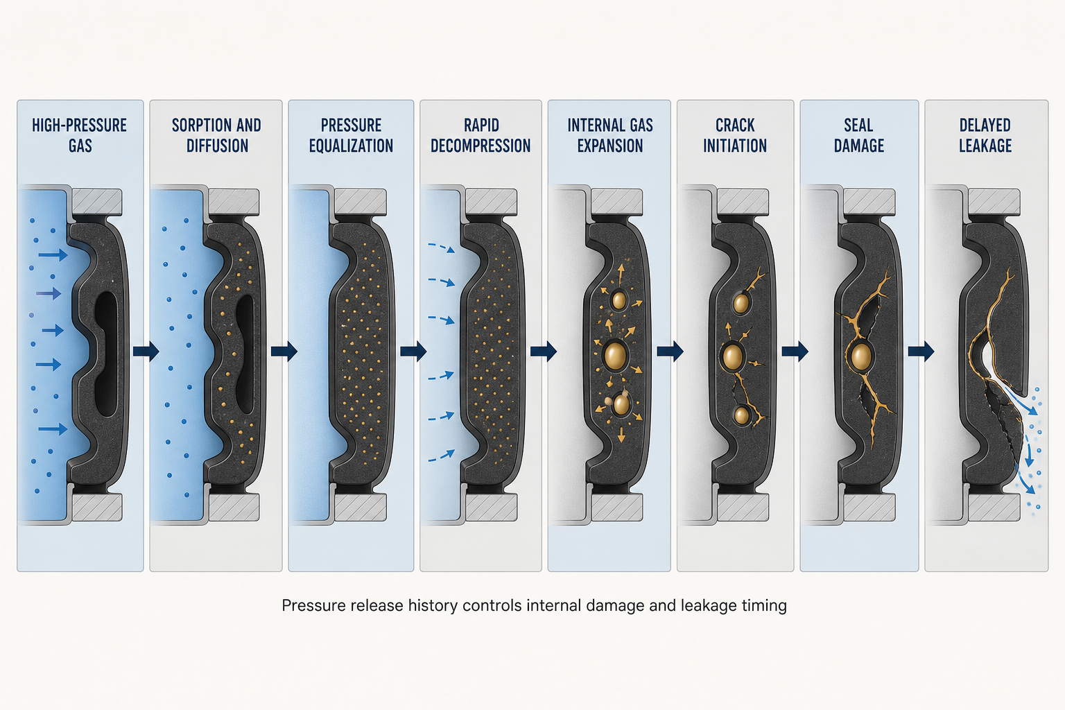
Rapid gas decompression (RGD) failure occurs when an elastomeric seal exposed to high-pressure gas is depressurized faster than gas can leave its internal structure. External pressure falls first while sorbed gas remains and expands. If local tensile stress exceeds crack resistance, blisters, void growth, cracks, delamination or rupture can develop. Leakage may be immediate or delayed until re-pressurization and cycling.
RGD is a coupled material-and-joint problem. Gas, pressure, temperature, exposure duration, formulation, defects, seal geometry, compression, clearance, restraint and decompression procedure all matter. A low-pressure leak test, hardness result, tensile result or single successful pressure release cannot independently qualify a seal for RGD service.
High-Pressure Gas Seal Architecture and Failure Boundaries
An O-ring, gasket, lip seal or piston seal separates high and low pressure through contact with a housing, shaft, piston or groove wall. A backup ring restricts movement toward a clearance gap but does not remove gas sorption or internal expansion. Static seals mainly experience compression and cycling; dynamic seals add friction, sliding damage, twisting and contamination.
The boundary includes the gas exposure zone, seal body, groove, low-pressure clearance and external environment. Gas can enter the bulk, migrate along an interface or exploit a cut, void or imperfect contact path. Compression, gap and pressure direction influence contact, extrusion and crack opening, so RGD assessment must use the actual architecture.
Table I. High-Pressure Gas Seal Zones and Failure Boundaries
| Seal zone | Adjacent pressure or medium | Main sealing function | RGD-related risk | Verification focus |
| High-pressure face | Compressed gas | Pressure separation | Sorption and pressure loading | Pressure history and morphology |
| Elastomer body | Gas and seal contact | Contact retention | Internal void growth and cracking | Sectioning and microscopy |
| Low-pressure face | Low pressure or vacuum | Leakage boundary | Delayed opening and crack leakage | Leak testing after waiting period |
| Groove and gap | Housing and clearance | Restraint and anti-extrusion | Extrusion and stress concentration | Gap, surface and backup-ring check |
| External environment | Ambient medium | Containment outside seal | Detected leakage or test artifact | Temperature and instrument control |
The table separates the locations where pressure is applied, where damage can initiate, and where leakage is finally detected. A measured leak identifies a containment problem; it does not, by itself, identify RGD as the cause.
Gas Sorption, Diffusion and Pressure Equalization Inside Elastomers
High-pressure gas may dissolve in the polymer or occupy free volume and interfaces. Sorption depends on gas, pressure, temperature, chemistry, crosslink structure, filler interfaces and exposure duration. Diffusion redistributes gas through the section, but the exposed surface, centre, moulding defects and high-strain zones may retain different concentrations. Desorption is also time-dependent.
When external pressure falls rapidly, internal gas pressure can lag behind the boundary condition and load voids or weak interfaces. Temperature changes affect solubility, diffusion, modulus and fracture resistance together. Permeation is gradual transport; RGD is damage caused by expansion of retained gas. No single solubility, diffusion coefficient or saturation time applies to every gas and elastomer.
Rapid Decompression, Internal Gas Expansion and Crack Initiation
The critical sequence is external pressure release, internal pressure lag, gas expansion, local stress increase, void growth, crack initiation and propagation. A faster release can increase pressure mismatch, but initial and final pressure, exposure, temperature, section size, constraint and defects also govern damage.
Cracks may begin at an internal void, weak filler interface, incompletely cured region or geometric stress concentration. Restraint and loading direction influence radial, circumferential or axial cracking. Blistering may precede rupture, while hidden cracks can open during later compression, re-pressurization or cycling.
Material Formulation, Defects and RGD Resistance
NBR, HNBR, FKM, EPDM, PU and FFKM can respond differently because gas compatibility, polarity, crosslink density, filler system and cure quality differ. Filled elastomers may gain strength or tear resistance, yet poor dispersion, weak interfaces or voids can create crack-initiation sites. Hardness and tensile strength are descriptive properties, not standalone RGD measures; higher hardness can improve extrusion resistance while reducing strain accommodation in another condition.
Selection must consider sorption, permeability, chemical compatibility, temperature, low-temperature flexibility, compression recovery, compression set, friction and defect control. Performance in hydrogen does not automatically predict methane, carbon dioxide, nitrogen or helium service. Evidence should be condition-specific and supported by batch and cure control.
Seal Geometry, Compression, Extrusion and Pressure-Cycle Interaction
RGD resistance depends on shape and restraint. Cross-section, groove fill, compression, installation stretch, clearance, pressure direction, surface finish and tolerances determine contact pressure and free volume. Excessive compression can increase strain and extrusion; insufficient compression can permit initial leakage and interface migration. A backup ring limits gap movement but cannot eliminate internal expansion.
Twisting, pinching, cutting, abrasion and contamination can create paths that resemble RGD. Contact may recover while internal cracks remain, or may be lost through permanent set. Inspection must link geometry, assembly condition and pressure history before assigning a mechanism.
Operating Conditions, Decompression Procedure and Cycle History
Relevant history includes pressurization, holding, decompression, re-pressurization, idle time and cycling. One long exposure and many short exposures can produce different gas distributions. Immediate re-pressurization can extend hidden damage. Controlled decompression may reduce mismatch but does not prove prior exposure was harmless.
Temperature affects sorption, desorption, modulus, toughness and compression recovery. Low temperature can reduce flexibility; high temperature can soften the elastomer or accelerate aging. Moisture, oil mist, cleaners and contaminants can alter swelling, hardening or interface strength. Qualification must record gas, pressure, temperature, exposure, decompression and cycle history.
Table II. Rapid Decompression Risk-Factor Matrix
| Risk factor | Primary effect | Secondary effect | Potential failure mode | Required measurement | Main limitation |
| Gas and pressure | Sorption and loading | Internal pressure retention | Blistering or cracking | Gas, pressure and exposure record | Does not prove damage alone |
| Exposure duration | Higher gas inventory | Delayed desorption | Delayed leakage | Time and temperature history | Material-dependent response |
| Decompression rate | Pressure mismatch | Void expansion | Internal rupture | Time-resolved pressure trace | No universal threshold |
| Temperature | Diffusion and modulus change | Toughness variation | Crack growth or swelling | Seal temperature record | Coupled effects are difficult to isolate |
| Geometry and gap | Constraint and extrusion | Stress concentration | Extrusion or crack opening | Dimensions and assembly inspection | Actual tolerances may vary |
| Defect population | Local weak points | Early crack initiation | Internal cracking | Sectioning and microscopy | Sampling may miss rare defects |
The matrix is a screening framework, not a universal rating system. The same pressure-release procedure can produce different results when material batch, section size, temperature or restraint changes.
Leakage Diagnosis, RGD Testing and Maintenance Decisions
Diagnosis should distinguish external or internal leakage, permeation, interface leakage, extrusion, compression-set loss, chemical swelling, mechanical damage and delayed leakage. Pressure decay must be interpreted with test volume, temperature, gas state, sensor accuracy and system leakage. Helium or hydrogen detection can locate a leak but cannot prove RGD. Surface inspection finds rupture or extrusion; sectioning and microscopy identify internal cracks, blisters, delamination, filler debonding and cure defects.
Testing should progress from material exposure to component and seal validation. Record gas, pressure, temperature, exposure, decompression, compression, gap, surface, cycles, leak criterion and inspection method. Coupons cannot reproduce every groove effect, while a leak test without sectioning may miss internal damage. After an abnormal event, preserve the seal, verify material and batch, inspect the groove and backup ring, and assess reuse only with mechanism-specific evidence. Replacement requires compatibility, dimensions, assembly, lubrication and post-maintenance verification.
Table III. RGD Inspection and Testing Guide
| Test or inspection | Test objective | Key variable | Detectable issue | Suitable stage | Main limitation |
| High-pressure gas exposure | Establish gas history | Gas, pressure, time, temperature | Sorption and swelling tendency | Material screening | Coupon not equal to seal |
| Controlled or rapid decompression | Reproduce release event | Pressure trace and rate | RGD damage initiation | Qualification | Procedure-specific result |
| Leak and pressure-decay test | Measure containment | Leak rate, volume, temperature | External leakage or artifacts | Component and field | Does not identify cause alone |
| Visual and dimensional check | Find gross change | Surface, section, set, extrusion | Rupture, extrusion, distortion | Pre and post test | May miss internal cracks |
| Cross-section and microscopy | Classify morphology | Crack direction and interfaces | Blistering, voids, delamination | Failure analysis | Sampling can alter evidence |
| Material and hardness mapping | Check batch or aging change | Hardness, cure, chemistry | Hardening, softening, poor cure | Corrective action | Not a standalone RGD proof |
A valid conclusion requires agreement between the pressure history, leakage result, material evidence, geometry and damage morphology. If these records disagree, the failure classification should remain conditional rather than being assigned from one observation.
FMEA, Reliability Planning, Conclusion and Engineering FAQ
FMEA Risk Analysis
The following RPN values are illustrative engineering risk rankings, not field statistics or experimental results. They should be recalculated using the organization’s severity, occurrence and detection definitions.
Table IV. Rubber Seal Rapid-Decompression FMEA and RPN Analysis
| Failure mode | Cause | Local effect | System effect | Detection method | RPN | Corrective action |
| Internal cracking | Fast release with retained gas | Void growth and crack path | Delayed external leakage | Sectioning and leak test | 280 | Condition-specific RGD qualification |
| Internal blistering | Gas accumulation at defect | Local separation and swelling | Contact instability | Visual and microscopy | 240 | Control voids and filler bonding |
| Seal extrusion | Large gap or weak restraint | Material displaced to gap | Leakage and damage | Gap and surface inspection | 210 | Review gap and backup support |
| Poor cure or dispersion | Process variation | Weak local fracture resistance | Early failure in service | Batch and material analysis | 220 | Tighten cure and mixing control |
| Chemical swelling | Incompatible gas or fluid | Softening and dimensional change | Loss of contact | Chemistry and dimensions | 180 | Verify compatibility and exposure |
| Permeation misdiagnosed as RGD | Gradual gas transport | No structural rupture | Incorrect corrective action | Time-dependent leak test | 150 | Separate transport from damage |
| Installation damage | Cut, twist or contamination | Pre-existing leak path | Immediate or delayed leak | Assembly inspection | 170 | Improve handling and inspection |
| Post-test inspection gap | No sectioning or waiting period | Hidden damage remains | Unexpected later leakage | Audit of records | 230 | Define evidence and hold period |
Reliability Planning and Conclusion
Reliability records should include seal geometry and batch, gas, pressure, temperature, exposure, decompression time and rate, compression, gap, backup-ring condition, surface, lubrication, leakage, pressure decay, crack location and maintenance history. Maintenance may be event-, trend-, cycle- or risk-based, but a laboratory result must not be converted into a universal field lifetime.
RGD is a pressure-release history acting on a gas-loaded elastomer with a particular formulation, defect population and geometry. Sorption and diffusion establish the internal condition; decompression creates imbalance; expansion drives damage; geometry and restraint determine how damage becomes leakage. Reliable decisions require condition-specific testing, controlled procedures, preserved evidence and replacement verification.
Engineering FAQ
Q:What is rapid gas decompression failure in an elastomeric seal?
A:It is structural damage caused when gas retained inside an elastomer expands after external pressure falls rapidly, producing blisters, internal cracks or rupture.
Q:How does high-pressure gas enter a rubber seal?
A:Gas can dissolve in the polymer, occupy free volume, diffuse through the section or migrate along defects and interfaces. The amount depends on gas, pressure, temperature, formulation and exposure time.
Q:Why can a rubber seal crack after pressure is released?
A:The external pressure may fall faster than internal gas can desorb. The retained gas then expands and loads voids or weak interfaces, which can initiate and extend cracks.
Q:Is rapid gas decompression the same as gas permeation?
A:No. Permeation is gradual gas transport through a material. RGD is pressure-release damage caused by expansion of retained gas, although both may affect leakage.
Q;Can hardness alone predict RGD resistance?
A:No. Hardness does not describe gas sorption, defect population, filler bonding, cure uniformity or the response of the actual seal geometry.
Q:Why may leakage appear after a delay?
A:Internal cracks may not connect to the surface immediately. Re-pressurization, compression recovery and later cycling can open a path after the first inspection.
Q:How do geometry and backup rings influence RGD damage?
A:They change compression, free volume, restraint and extrusion clearance. A backup ring can reduce extrusion while leaving internal gas expansion risk unresolved.
Q:Which tests are needed after a suspected event?
A:Record the pressure history, perform a controlled leak test, inspect dimensions and surfaces, preserve the seal, and use cross-section or microscopy where internal damage is plausible.
Q:Should a seal be reused after a rapid decompression event?
A:Not without a documented assessment. Immediate leak-free behaviour does not exclude hidden damage or delayed leakage, so reuse requires evidence appropriate to the seal and service conditions.
Post time: Sep-02-2026