
Executive Summary
In a hygienic pump, the seal groove is both a sealing feature and a flow-access, venting and drainage boundary. Depth, side clearance, corners, surface condition and compression can create a product-retention zone that is difficult to wet, scrub and drain during CIP. The same geometry may retain cleaning fluid, water or air, which must be distinguished from product retention and microbial harborage.
Food and beverage systems may face spoilage, allergen carryover, microbial growth or cross-contamination. Biopharmaceutical service may involve protein, cell, media, endotoxin or cleaning-agent residue despite a clean-looking surface. Visual cleanliness does not prove chemical, microbiological or sterilization control.
Cleanability cannot be assigned to seal material alone. Geometry, compression, gland fill, flow access, wall shear, air removal, drainage, surface condition and verification must be evaluated as one system through structural inspection, CIP records, coverage studies, residue detection, microbiological assessment and repeated-cycle testing.
Hygienic Pump Seal-Groove Architecture and Flow Access
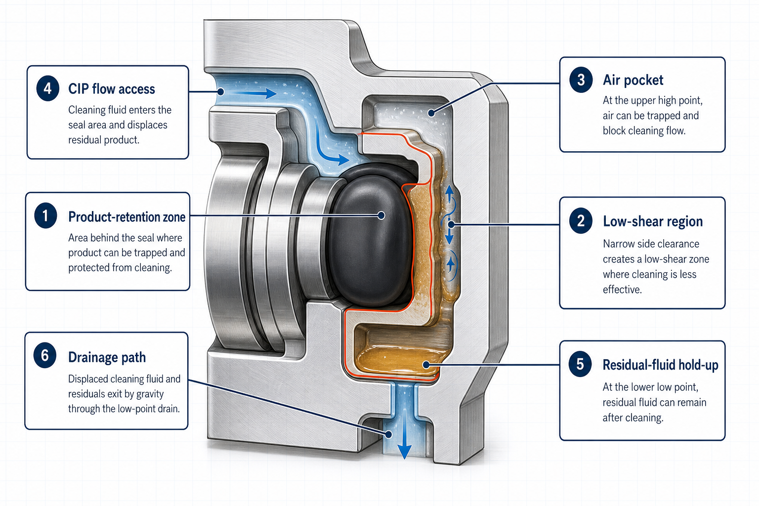
A sanitary pump may contain an O-ring groove, gasket groove, mechanical-seal recess, static-seal pocket, seal-retaining shoulder, cover-to-body interface, shaft-to-housing interface, pump-head or casing joint, and impeller-side or drive-side seal. Flush, drain and vent paths can improve access, but do not prove that the groove is reached, wetted, sheared and drained.
The design review should ask whether fluid reaches the groove, product-contact surface and seal backside; whether product is displaced; whether the groove drains in the installed orientation; and whether air escapes. Excessive depth, side clearance, sharp transitions, blind ends, low points and inverted pockets make each question harder.
Gland fill and seal compression are equally important. A seal may satisfy static leakage requirements yet shield a groove surface from flow, while insufficient fill may leave a product-holding annulus. Compression set, roughness, machining marks, scratches, corrosion and seal flash can change adhesion and create shadow zones.
The relevant boundary is the assembled, product-exposed and installed condition, not an isolated drawing. Bench drainage may differ from installed drainage, and a surface visible after seal removal may be hidden while compressed. Review flow, contact, backside, drainage and venting together.
Table 1 – Seal-Groove Features That Influence Retention and Cleaning
| Geometric Feature | Possible Retention Mechanism | Cleaning or Drainage Effect | Hygienic Risk | Recommended Design Check |
| Excessive depth | Large hold-up volume behind seal | Weak exchange and slow drainage | Product or chemical residue | Inspect assembled gland fill and flush access |
| Narrow side clearance | Trapped film or capillary hold-up | Low wetting and low wall shear | Residual product | Review tolerance stack and aged-seal fit |
| Blind end or step | Local flow shadow and particle deposit | Incomplete displacement | Microbial harborage | Use borescope or seal-removal inspection |
| High point without vent | Air pocket blocks liquid contact | Incomplete wetting | Uncleaned surface | Confirm venting during coverage study |
| Low point or inverted pocket | Residual water or cleaning fluid | Poor drainability | Diluted residue or chemical carryover | Check installed orientation and low-point drain |
| Roughness, scratch or corrosion | Adhesion and corrosion residue | Harder chemical removal | Persistent residue | Measure surface condition and inspect after cycles |
Retention Mechanisms and Cleaning Dead Spots
A product-retention zone remains after production because displacement, exchange or drainage is incomplete. Fluid hold-up may involve product, rinse water, cleaning chemical or condensate. A cleaning dead spot lacks sufficient wetting, chemical contact, wall shear, contact time or removal path.
The seal backside is a common low-shear region. Product can enter through pressure fluctuation, shaft movement, thermal expansion or tolerance, while CIP provides weak exchange. A narrow side gap can act as a capillary region with viscous products, proteins, fats, sugars, fibers or solids. Ends, corners and steps can become flow shadows.
Air pockets are different: air can remain at a high point while liquid bypasses the seal, leaving intermittent or incomplete wetting. At a low point, water or cleaning fluid may remain after drainage, dilute a later stage, concentrate during evaporation or support microbial persistence. Neither condition should be labelled product retention without evidence.
Solid, crystallized or corroded residue requires separate attribution. Particles may originate from product, seal wear, maintenance debris or corrosion; surface damage can increase adhesion independently of geometry. Biofilm and microbial harborage require microbiological or sanitation evidence.
Cleaning fluid passing a location proves access only, not wetting, chemical removal, wall shear, displacement or drainage. Flow direction, pulsing, viscosity, surface tension, foam, air release, attitude and drying history influence the result.
Table 2 – Retention and Dead-Spot Mechanisms in Hygienic Seal Grooves
| Retention Mechanism | Typical Location | Why Cleaning Is Limited | Potential Residue | Required Confirmation |
| Product retained behind seal | Seal backside or deep gland | Restricted exchange and shielding | Product film, protein or fat | Seal removal plus product-specific residue test |
| Cleaning fluid hold-up | Low point or pocket | Slow drainage or trapped liquid | Chemical or diluted residue | Drain observation and rinse monitoring |
| Air pocket | High point or closed recess | Surface remains incompletely wetted | Unremoved product film | Coverage test with venting review |
| Low-shear region | Corner, step or narrow gap | Insufficient local wall shear | Adhered or dried residue | Flow-path study and swab or rinse sampling |
| Solid or crystallized deposit | Groove bottom or damaged surface | Particle cannot be displaced | Crystal, scale or powder | Visual inspection after seal removal |
| Biofilm or microbial harborage | Hidden wet region | Repeated residual conditions | Microbial growth | Sanitation or microbiological verification |
| Corrosion-related residue | Rough or damaged metal | Adhesion and local chemistry change | Oxide or corrosion product | Surface inspection and material review |
CIP, SIP, Flushing and Drainability Performance
CIP, flushing, sanitation and SIP are different verification concepts. A rinse may remove loose material but leave an adhered film; a caustic or acid stage may change residue chemistry without proving displacement; sanitation may reduce microbial risk without proving product or cleaning-agent removal. SIP requires its own validated heat, exposure and penetration logic.
Evaluate the sequence as pre-rinse, chemical cleaning, intermediate rinse, final rinse and the applicable disinfection or sterilization stage. Flow direction, rate, pressure, pulsation, valve switching, wall shear, temperature, concentration and contact time matter. Orientation determines low-point drainage and high-point venting; foam and bubbles can reduce contact despite adequate bulk flow.
Verification should distinguish fluid reaching, wetting, displacing, shearing, chemically removing and flushing residue, and controlling microbial risk. These are successive claims. Changes in seal, product, chemistry, temperature, orientation or pump configuration may require revalidation.
Table 3 – Cleaning-Cycle Variables and Seal-Groove Performance
| Cleaning Variable | Effect on Groove Cleaning | Possible Limitation | Residual-Risk Indicator | Verification Method |
| Flow and pressure | Controls exchange and shear | Pulsation or bypass may shield groove | Persistent local residue | Record values and inspect coverage |
| Flow direction | Changes access to shoulders and ends | Shadow zone during one-way flow | Asymmetric residue | Bidirectional or path-specific study |
| Temperature | Changes viscosity and reaction rate | May accelerate seal ageing | Release drift after cycles | Trend temperature with residue results |
| Chemical concentration | Supports residue removal | Limited by compatibility or dilution | Cleaning-agent or product residue | Concentration and conductivity checks |
| Contact time | Allows chemical action | Cannot compensate for inaccessible geometry | Repeatable residue pocket | Cycle record plus residue test |
| Venting and drainage | Enables wetting and liquid removal | Air pocket or low-point hold-up | Water, chemical or microbial risk | Orientation, drain and vent observation |
Material, Surface and Product Compatibility
Material selection affects cleanability, but a material name is not sufficient. EPDM, FKM/FPM, FFKM, silicone, NBR/HNBR, PTFE-based designs, polyurethane and filled elastomers differ in surface energy, friction, swelling, compression recovery, extractables, leachables and product adhesion. Evidence must use the actual compound, finish, product and cleaning chemistry.
Swelling can reduce flush access; compression set can close an exchange path; hardening, cracking, flash, parting lines and roughening can increase adhesion or create a retention pocket. Acids, alkalis, solvents, oxidants, chlorine-containing media, disinfectants and high-temperature steam may alter the surface or accelerate ageing.
Viscosity, solids, fibers, proteins, fats, sugars, particles and crystallization tendency determine residue release. Chemical resistance is not equivalent to cleanability. Assess surface cleanability, product adhesion, residue release, swelling, groove-fit change, compression set, cracking, extractables, leachables, microbial-harbor risk and repeat-cleaning durability within the tested geometry and process.
Characterization and Benchmark Testing
Characterization starts before residue testing. Inspect geometry, dimensions, roughness, gland fill, compression, tolerance stack, orientation, flow path, flush ports, vents, low points and hold-up volume. Compare new, aged and product-exposed seals, and inspect the groove after removal to separate design limits from wear, swelling, compression set or maintenance.
Next, evaluate coverage and process parameters. Riboflavin or fluorescent testing may be appropriate when it represents the wetting question. Record flow, pressure, temperature, chemical concentration, conductivity, rinse response and drainage. The result should identify whether the groove was reached, wetted, displaced and drained, not only report bulk skid conditions.
Chemical verification should use the relevant residue definition: total organic carbon, product-specific, protein, allergen or cleaning-agent tests, conductivity, rinse sampling or swab sampling. Accessible-surface sampling can miss the seal backside; locations should follow the suspected mechanism and include seal removal when needed.
Microbiological verification may include ATP, bioburden, endotoxin, challenge or sanitation monitoring. These methods are not interchangeable. Visual, chemical, microbiological, drainability, sterilization and cross-contamination outputs differ. Repeat-cycle and post-maintenance tests address ageing and change.
Validation Path for Hygienic Seal-Groove Cleanability
- • Design and geometry — Dimensional inspection, surface roughness, gland-fill, orientation and drainability review. Confirms geometry and drainage assumptions, but not actual residue removal or microbial control.
- • Flow access and coverage — Flow-path inspection, venting review and coverage testing. Confirms whether the target region is reached or wetted, but not complete chemical removal or sanitation.
- • Chemical residue — Conductivity, total organic carbon, product-specific, protein, allergen or cleaning-agent testing, with rinse or swab sampling. Confirms the selected residue indicator at sampled locations, but not unsampled hidden surfaces or sterilization.
- • Microbiological and sanitation — ATP, bioburden, endotoxin, microbial challenge or applicable monitoring. Supports the selected microbial-risk assessment, but does not replace geometry, drainage or chemical verification.
- • Repeatability and maintenance — Repeated cycles, aged seals, product-exposed seals and post-maintenance checks. Tests stability of the evaluated configuration, but not untested products, chemistries or orientations.
Engineering Controls and Maintenance Strategy
The first control is geometry. Reduce blind pockets, unnecessary depth, abrupt steps, sharp transitions and horizontal cavities. Provide a continuous, flushable and drainable groove; vent high points and drain low points in the installed orientation. Control compression and gland fill without inaccessible backside volume, and make flush paths inspectable.
The second control is surface and material condition. Select a compound with evidence for the product and cleaning chemistry, and evaluate adhesion, release, swelling, compression set, cracking and repeat-cleaning durability. Control roughness, machining direction, scratches, burrs, corrosion, weld transitions, flash, parting lines and seal damage.
The third control is process and maintenance discipline. Record CIP flow, temperature, chemistry, contact time, pressure, direction, venting and drainage. Confirm installation attitude and low-point discharge. Define seal removal, inspection, reassembly and replacement criteria. Prevent fibers, particles, lubricant and debris, and intensify verification for allergen, high-risk product or chemistry changes.
Do not use longer time or higher temperature to mask retention-prone geometry. Added intensity may miss a shielded region and accelerate swelling, compression set or ageing. For abnormal residues, investigate sampling, cycle parameters, drainage, product behavior, seal condition, geometry and maintenance using the actual product and cleaning formulation.
FMEA Risk Analysis
This qualitative FMEA does not assign an RPN. Risk depends on product, chemistry, flow, seal geometry, drainability, microbial sensitivity and cross-contamination consequence.
Table 4 – FMEA for Hygienic Pump Seal-Groove Retention and Cleaning Risk
| Failure Mode | Cause | Local Effect | System Effect | Detection Method | Control Action |
| Product trapped behind seal | Deep gland or restricted exchange | Residual product film | Carryover or microbial risk | Seal removal and residue test | Reduce hold-up and verify flush access |
| Residual fluid in a low-point groove | Poor orientation or drainage | Water or chemical hold-up | Dilution or chemical carryover | Drain observation and rinse monitoring | Provide low-point drainage |
| Air pocket preventing cleaning contact | Unvented high point | Incomplete wetting | Uncleaned surface | Coverage and vent review | Add vent path or revise orientation |
| Low-shear region in the seal recess | Corner, step or narrow gap | Adhered residue | Repeat cleaning failure | Flow study and swab sampling | Remove shadow zone or verify shear |
| Excessive gland depth or uncontrolled clearance | Uncontrolled geometry | Large hold-up volume | Persistent residue | Dimensional inspection | Control depth, tolerance and gland fill |
| Seal swelling reducing flush access | Chemical or product exposure | Reduced backside exchange | New cleaning dead spot | Aged-seal dimensional check | Confirm compatibility and replace when required |
| Seal compression set changing groove geometry | Thermal or cyclic ageing | Changed groove fit | Drainage or access drift | Compression and fit assessment | Set evidence-based replacement criteria |
| Surface roughness or corrosion increasing adhesion | Surface damage or cleaning chemistry | Higher product adhesion | Corrosion or residue risk | Surface inspection and roughness review | Repair, refinish or replace |
| Cleaning-agent residue after incomplete rinsing | Incomplete rinse or hold-up | Chemical film | Product impact or safety risk | Conductivity or chemistry test | Improve rinse and drainage |
| Microbial harborage in a hidden region | Repeated hidden wet residue | Persistent microbial niche | Sanitation or batch risk | Bioburden or sanitation verification | Remove geometry cause and verify |
| CIP parameters not reaching the seal groove | Bypass, pulse or blocked path | No effective exposure | Uncleaned seal region | Recorded flow and coverage study | Redesign path or control the cycle |
| Seal damage creating a retention pocket | Cut, flash or misassembly | Local retention site | Unstable cleanability | Seal removal inspection | Improve handling and assembly |
| Maintenance debris introduced into the groove | Fiber, particle or lubricant entry | Foreign residue | Product contamination | Post-maintenance inspection | Use controlled maintenance and release checks |
| Residue test performed only on accessible surfaces | Hidden surfaces excluded | False clean result | Unrecognized carryover | Sampling-map review | Sample hidden regions or remove the seal |
| Product or cleaning chemistry changed without revalidation | Uncontrolled process change | Changed residue behavior | Unconfirmed cleaning state | Change-control review | Reassess geometry, materials and cycle |
Conclusion
Retention zones and cleaning dead spots in hygienic pump seal grooves can affect product quality, microbial control, allergen management, batch changeover and validation. Assess geometry, compression, gland fill, surface condition, flow access, wall shear, venting, drainability, orientation, product behavior, chemistry, residue detection, microbiological verification, ageing and maintenance. Cleaning fluid reaching a groove does not prove wetting, scrubbing, removal, drainage or verification.
FAQ: Hygienic Pump Seal-Groove Cleanability and Validation
These questions address the design, cleaning and validation decisions most often raised when selecting, qualifying or maintaining a hygienic pump seal assembly. The answers are process-specific: the actual product, seal geometry, cleaning chemistry, equipment orientation and verification method determine the final engineering conclusion.
Q:What makes a hygienic pump seal groove difficult to clean?
A:The main contributors are excessive groove depth, narrow or uncontrolled clearances, blind ends, steps, rough surfaces, compressed-seal shadow zones, trapped air and poor drainage. A groove may meet static sealing requirements yet remain difficult to wet, shear and drain during CIP.
Q:How can product retention in a sanitary pump seal groove cause cross-contamination?
A:Residual product can remain behind a seal or in a low-shear pocket, then be released during a later batch or rinse stage. The risk depends on product viscosity, solids, adhesion, allergen or microbial sensitivity, and the effectiveness of displacement, chemical cleaning and residue verification.
Q:How do you verify CIP coverage inside a hygienic pump seal groove?
A:Use a combination of flow-path and venting review, coverage testing where appropriate, recorded CIP parameters, targeted swab or rinse sampling, and product- or chemistry-specific residue detection. Bulk flow data or visual inspection alone cannot prove that a hidden groove surface was adequately cleaned.
Q:How should drainability and air removal be checked in a sanitary pump seal assembly?
A:Review the installed orientation, high-point venting, low-point drainage, trapped volume and post-cycle residual liquid. Observe the assembled pump after relevant cleaning stages and compare the result with rinse or residue monitoring; a bench-top orientation may not represent field drainability.
Q:Which seal-groove design features improve hygienic pump cleanability?
A:Prefer a continuous, inspectable and flushable groove with controlled seal compression, limited hold-up volume, no unnecessary blind pockets, effective venting and reliable low-point drainage. Surface roughness, scratches, corrosion, seal flash and uncontrolled tolerances should also be controlled.
Q:How do seal swelling and compression set affect CIP performance?
A:Swelling can reduce flush access behind the seal, while compression set can change gland fill, contact pressure and drainage geometry. Compare new, aged and product-exposed seals, and recheck cleanability after significant material, chemistry, temperature or maintenance changes.
Q:When should a hygienic pump seal be replaced or the cleaning process revalidated?
A:Replacement or revalidation should be considered when inspection or testing shows swelling, compression set, cracking, roughening, leakage, residue persistence, changed product or cleaning chemistry, altered equipment orientation or post-maintenance cleanability drift. No universal replacement interval can be assigned without process-specific evidence.
Post time: Sep-19-2026