
Executive Summary
Rotary oil-seal leakage under eccentric shaft motion is a dynamic contact problem, not a simple material-quality judgment. The sealing boundary is created by the rotary shaft, housing bore, seal case, primary lip, garter spring, oil side, air side and lubrication film. Static fit can appear correct while operating motion redistributes lip contact around the shaft circumference.
Shaft eccentricity, radial runout, axial runout, shaft tilt, bearing clearance and housing distortion can combine during rotation. Their effect is not one isolated dimension; it is a changing relative motion between the shaft surface and the lip. One angular sector may experience local contact overload, frictional heat and accelerated wear, while another may lose contact reserve and permit oil-film migration. The leakage process often begins before external oil droplets appear, through temperature rise, torque change, lip polishing, shaft-track development or wear-debris generation.
A static leakage test, short low-speed trial or initially dry exterior cannot prove long-term rotary seal reliability under oil temperature change, pressure differential, speed cycling, shaft orbit change and debris accumulation. A credible assessment must connect the shaft-motion source, the lip-contact response, the lubrication state, the wear morphology and the leakage evidence.
Rotary Seal Boundary
A rotary oil seal contains several sealing functions that must not be mixed. The primary lip meters oil at the shaft surface. The dust lip limits external particle and water ingress, but it cannot replace the primary lip or correct loss of dynamic contact. The outer diameter of the seal case forms a static seal against the bore. The garter spring provides preload, yet the actual lip load is modified by elastomer deformation, temperature, pressure-side loading, oil-film thickness and shaft motion.
Leakage may therefore originate from the dynamic lip-shaft interface, the static outer-diameter fit, a damaged installation surface, a worn shaft groove, shaft lead marks or pressure-driven oil movement. Eccentricity is relevant only when it changes the lip’s ability to track the shaft. If oil appears outside the assembly, the first question is not whether the seal is defective, but which boundary failed: lip contact, case-to-bore sealing, shaft-surface pumping, installation damage or system pressure control.
The oil side and air side impose different stresses. Oil-side pressure, oil level and churning can feed more fluid than the lip can meter. Air-side dust can abrade the contact band and turn a small tracking error into permanent wear. Bore distortion can create a static leakage path even when the primary lip is still sealing. For this reason, leakage diagnosis must map the boundary before assigning the cause to eccentricity or seal compound.
Table I: Rotary Oil-Seal Zones and Functions
| Seal zone | Adjacent component | Main function | Eccentricity risk | Leakage consequence | Verification focus |
| Primary lip | Shaft and oil | Dynamic oil control | Uneven tracking | Lip leakage | Wear band |
| Dust lip | Air side | Particle exclusion | Lift or rub | Dust ingress | Outer lip condition |
| Outer diameter | Housing bore | Static sealing | Case distortion | OD leakage | Press-fit trace |
| Shaft track | Lip contact | Film support | Groove or lead | Axial oil migration | Surface microscopy |
| Spring zone | Lip back side | Preload support | Displacement | Contact loss | Spring position |
Eccentricity and Runout
Eccentricity describes offset between a rotational axis and a related geometric center. Radial runout describes radial movement of a measured shaft surface relative to a datum during rotation. Axial runout describes axial face movement. Axial displacement is translation along the shaft axis. Shaft tilt is angular error, not radial runout. Concentricity and coaxiality describe static geometry; they do not prove that the running shaft line remains stable under load, temperature and bearing motion.
This distinction matters because the sealing lip responds to relative dynamic displacement, not to a drawing note in isolation. Bearing clearance may allow operating movement without proving that the shaft is permanently bent. Rotor load, belt tension, gear mesh force, pump hydraulic load, thermal growth, housing distortion and seal-bore misalignment may amplify lip motion after assembly. The same shaft can show different effective motion at the bearing, at the seal track and at a distant measurement point.
The practical error is to treat runout as direct lip pressure. The same measured motion can produce different contact effects when shaft diameter, seal cross-section, spring load, oil viscosity, pressure side, speed and support stiffness change. Runout measurement depends on datum, probe position, rotation speed and support condition. The lip experiences amplitude, phase and frequency of relative motion; the inspection report records only a measurement condition. When leakage appears only after warm-up, acceleration or load change, operating verification is more important than a static number.
Lip Contact Redistribution
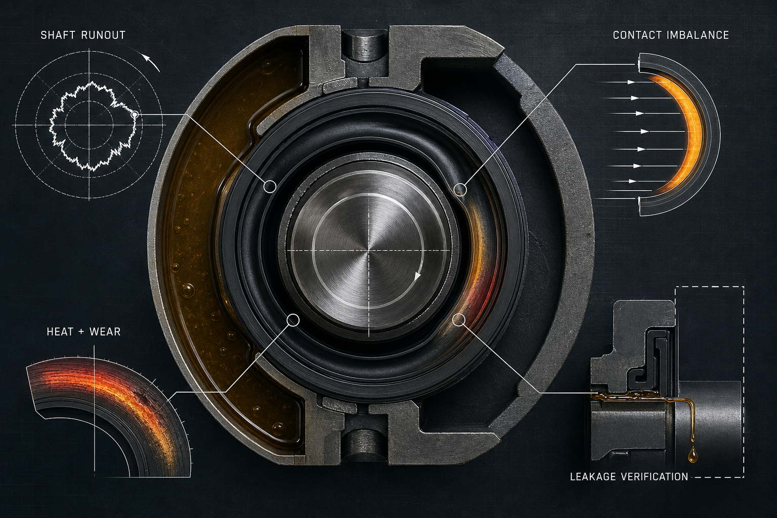
The lip is not a rigid stationary ring. It must follow a moving shaft while maintaining enough interference to retain oil and enough lubrication to avoid destructive wear. When the shaft centerline is eccentric or tilted, the contact band is redistributed around the circumference. The overloaded sector develops higher pressure, thinner film, more friction and faster heat generation. The underloaded sector loses contact reserve and may allow oil to migrate through a transient micro-gap.
This redistribution is not constant around the seal. As the shaft rotates, the high-load region and low-load region can move relative to the lip. If the lip has sufficient followability, the interface remains controlled. If the lip cannot follow the motion, it may flutter, roll, invert locally or slide on an unstable film. Lip followability depends on elastomer modulus, garter-spring load, lip angle, contact width, pressure-side loading, temperature, oil viscosity and shaft finish.
Contact imbalance also evolves with wear. Local overload can polish the shaft and lip, reducing the original sealing edge. Local underload can leave an intermittent oil film that becomes visible only at certain speeds or pressure states. Once wear begins, the seal no longer behaves like a new part: the wear track, transfer film, shaft groove and debris field become part of the operating geometry. Static contact marks show where the lip touched at rest; they cannot prove stable rotating pressure distribution.
Table II: Shaft Geometry, Lip Contact and Leakage-Risk Matrix
| Operating factor | Primary effect | Secondary effect | Failure mode | Measurement | Limitation |
| Eccentricity | Offset contact | Pressure split | Local overload | Alignment check | Static datum only |
| Radial runout | Cyclic lip motion | Heat variation | Dynamic leakage | Dial or sensor trace | Location dependent |
| Shaft tilt | Angled contact | Uneven width | Lip wear | Coaxiality review | Not pure runout |
| Bearing clearance | Running displacement | Lip tracking demand | Contact loss | Bearing inspection | Load dependent |
| Oil pressure | Lip deflection | Film change | Oil migration | Pressure record | System specific |
Lubrication, Heat and Wear
A rotary oil seal operates between sealing and lubrication. Too little film drives boundary lubrication, adhesive wear, abrasive wear and local flash-temperature risk. Too much film, or contact pressure that is too low, can become an oil migration path. Eccentricity makes this balance cyclic: the lip may be overloaded during part of each revolution and under-supported during another part.
Oil viscosity, bulk oil temperature, aeration, contamination, additive condition and pressure differential all influence the film. Housing or sump temperature does not necessarily equal lip contact temperature, because heat is generated at the small moving contact band. Start-up, low-temperature operation, high-speed operation and repeated acceleration may each shift the lubrication regime. A seal that survives one condition can become unstable when viscosity falls, pressure rises, oil aeration increases or the shaft orbit changes.
Wear is not merely material removal. Abrasive particles can cut both lip and shaft. Adhesive transfer can alter the contact chemistry and make friction unstable. Fatigue wear can form a circumferential track that later guides oil. Shaft scoring, shaft grooving and unstable transfer film may create a secondary leakage path even if the original eccentricity is reduced. The visible leak is often the late result of heat and wear, not the first event in the chain.
This is why temperature, friction or oil mist must be interpreted as mechanism indicators, not as automatic proof of eccentricity. The same temperature rise may come from high oil temperature, bearing heat, external heat soak, overpressure or insufficient lubrication. The engineer must connect the thermal symptom to contact marks, shaft morphology, oil condition and dynamic motion before assigning root cause.
Surface and Installation Controls
Shaft surface condition can either support oil-film control or defeat it. Roughness, waviness, shaft lead, helix marks, grinding direction, scoring, corrosion pits and previous wear grooves can pump or guide oil axially. A surface that is too rough accelerates lip wear; a surface that is excessively polished may reduce film retention. Surface hardness and sleeve condition also affect whether the shaft or the lip becomes the dominant wear partner.
The housing side is equally important. Bore roundness, bore diameter, press-fit condition and seal-case deformation influence the static outer-diameter seal and the lip’s alignment. Installation depth can place the lip on a previous wear track or too near a shoulder. Incorrect seal orientation, spring displacement, lip inversion, assembly scratches and poor use of a protective sleeve may be misread as eccentricity.
A replacement seal should therefore not be treated as a reset. Before installation, the shaft track, bore, chamfer, spring retention, lip direction, seating depth and lubrication during assembly must be controlled. If the new lip is placed on the same groove or the bore still distorts the case, the failure can return quickly and appear to be a batch or material issue. The corrective action must match the boundary that actually failed.
Dynamic Diagnosis
Dynamic leakage diagnosis must separate eccentricity from oil, pressure, bearing and installation effects. External oil film does not by itself prove a defective lip. Oil loss may come from static outer-diameter leakage, shaft-surface pumping, pressure-driven migration, system connections, venting behavior, evaporation or measurement error. Temperature rise may come from lip friction, bearing heat, oil temperature, external heat or sensor location.
Runout data also cannot prove lip-contact imbalance unless contact marks, wear pattern, shaft condition and running state support the same conclusion. Useful evidence includes shaft-runout measurement, alignment check, bore inspection, oil-pressure record, oil-temperature trend, leakage trend, friction or torque monitoring, fluorescent dye tracing, contact-pattern inspection, surface microscopy, wear-debris analysis and bearing inspection.
Teardown should preserve the seal and shaft track before cleaning. Inspect lip width, circumferential wear uniformity, local overheating, spring position, shaft groove, lead direction, polishing marks and bore press-fit trace. If leakage is intermittent, test history matters: speed range, oil level, oil temperature, pressure state, direction changes, start-stop history and stabilization time may explain why a static test passed while rotation failed.
Table III: Rotary Oil-Seal Inspection and Verification Guide
| Inspection | Objective | Key variable | Detectable issue | Stage | Limitation |
| Runout check | Measure motion | Datum and location | Shaft movement | Assembly | Not lip pressure |
| Dye tracing | Locate path | Oil route | Leakage path | Operation | May miss early wear |
| Temperature trend | Find heat | Sensor location | Friction or bearing heat | Dynamic test | Indirect evidence |
| Torque trend | Track friction | Speed and oil | Overload | Commissioning | System noise |
| Teardown | Read morphology | Cleaning control | Lip or shaft wear | Failure analysis | Destructive |
FMEA Risk Analysis
The FMEA below focuses on eccentricity, lip tracking, lubrication instability and diagnostic error. It does not rank all possible oil-seal failures, and it does not represent field statistics. Its value is to force the investigation to connect shaft motion, lip response, surface condition and verification method before corrective action is selected.
Table IV: Rotary Oil-Seal Eccentricity FMEA and RPN Analysis
| Failure mode | Cause | Local effect | System effect | Detection | RPN | Corrective action |
| Radial runout | Bearing or shaft error | Cyclic lip motion | Dynamic leakage | Runout trace | 168 | Correct shaft support |
| Local overload | Eccentric contact | Heat and wear | Lip failure | Wear band | 150 | Improve alignment |
| Contact loss | Tilt or bore error | Oil migration | Intermittent leak | Dye trace | 144 | Correct bore and seating |
| Shaft lead | Grinding pattern | Axial pumping | Oil film outside | Microscopy | 126 | Repair or sleeve shaft |
| Spring displacement | Installation damage | Low preload | Early leakage | Teardown | 135 | Revise tooling |
| Weak retest | Static-only check | Missed dynamic leak | Repeat failure | Dynamic test | 120 | Requalify under rotation |
The RPN values are illustrative engineering risk rankings, not field statistics or experimental results.
Reliability Planning
Reliability planning should record shaft diameter, speed, material, hardness, roughness, waviness, lead, radial and axial runout, shaft tilt, bearing clearance, housing alignment, bore roundness, seal material, lip geometry, interference, spring condition, oil viscosity, temperature, pressure, oil level, aeration, operating hours, start-stop history, leakage trend, temperature trend, wear morphology and corrective action.
The record must distinguish design judgment, engineering estimate, laboratory observation and field data. Trend evidence matters more than one isolated result: rising temperature, changing torque, repeated oil mist, progressive shaft polishing and increasing debris can indicate that the lip is losing its stable operating window. A bench result from one shaft finish or oil condition cannot be converted into a universal field life.
Maintenance strategy should be evidence based. A leaking rotary seal may require shaft repair, sleeve installation, bore correction, bearing review, oil-condition control, installation-tool change, pressure reduction or dynamic requalification. One no-leak run after replacement is not proof of long-term tolerance to eccentricity, runout, speed cycling and thermal history.
Conclusion
Rotary oil-seal eccentricity becomes critical when shaft motion redistributes lip contact enough to change local pressure, film stability, heat generation and wear. Shaft runout, eccentricity, tilt and bearing movement are related but not interchangeable. The lip sees the combined operating displacement, not a single static tolerance number.
Corrective action should follow the evidence chain: define the leakage boundary, measure shaft and bore condition, inspect bearing support, review oil pressure and temperature, examine lip and shaft wear, and verify the seal dynamically. Only then can engineers decide whether the root cause is eccentricity, surface damage, lubrication starvation, overpressure, thermal aging, chemical swelling, installation damage or measurement error.
Engineering FAQ
Q:What is the difference between shaft eccentricity and radial runout?
A:Eccentricity is axis offset. Radial runout is measured surface movement during rotation relative to a datum.
Q:How does shaft misalignment create uneven lip contact?
A:It shifts the shaft relative to the lip, creating overloaded and underloaded sectors around the contact band.
Q:Why can a seal pass a static test but leak during rotation?
A:Static tests do not reproduce runout, oil-film change, heat generation, bearing movement or speed-related lip tracking.
Q:How do shaft finish and lead marks affect leakage?
A:Surface texture can wear the lip, disturb the film or guide oil axially along the shaft track.
Q:Can a new seal compensate for excessive shaft runout?
A:Only within the followability of its lip, spring, material and lubrication system; it cannot correct uncontrolled shaft motion.
Q:Why can leakage appear after temperature or speed increases?
A:Temperature and speed change oil viscosity, lip modulus, friction heat, shaft growth and dynamic contact stability.
Q:How should oil-seal wear marks be interpreted?
A:Compare circumferential uniformity, shaft track, spring condition, oil state, temperature history and runout evidence.
Q:Which checks are required before replacing a leaking rotary oil seal?
A:Check shaft track, runout, bore condition, bearing clearance, spring position, lip direction, installation depth and oil condition.
Q:How should bearing clearance be considered?
A:It may allow dynamic shaft displacement under load, so lip tracking must be evaluated in the running support condition.
Post time: Sep-07-2026