
Executive Summary
A semiconductor equipment rotary shaft seal must control more than gas leakage. It must also limit particle generation, friction, heat, outgassing, vacuum loss, process contamination and maintenance frequency while the shaft continues to move. These requirements make the application different from a general industrial shaft seal and from a pump mechanical seal designed mainly for liquid containment.
The critical variables are shaft surface condition, speed, runout, eccentricity, temperature, vacuum level, lubrication and seal structure. A lip seal, PTFE-based rotary seal, magnetic fluid seal, mechanical face seal, bellows-sealed structure or labyrinth arrangement may be appropriate in a defined envelope. None is universally best. Low friction can conflict with wear resistance, and low contact pressure can reduce heat while increasing leakage risk.
A reliable design therefore combines dynamic contact analysis, clean assembly, vacuum compatibility and time-based validation. Rotary cycling, torque, temperature rise, helium response, pressure behavior, particle evidence and post-test inspection should be interpreted as one evidence chain.
Rotary Shaft Sealing Physics
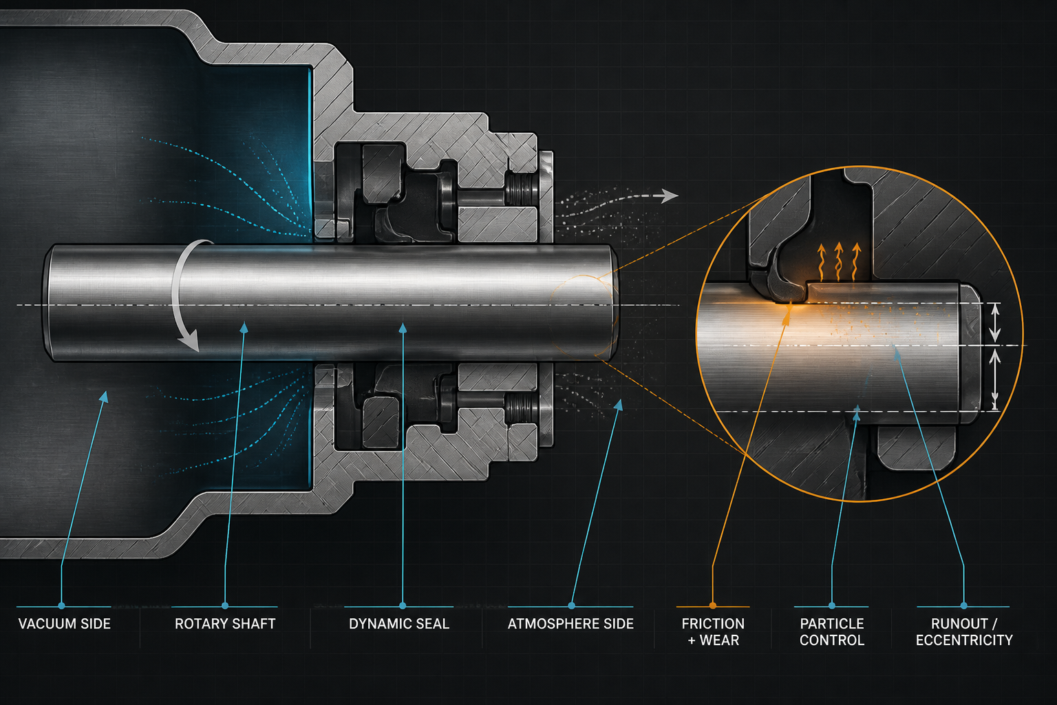
Dynamic sealing is the control of leakage across a moving interface. Sliding contact produces friction and wear; contact pressure must remain high enough to limit gas transport but low enough to avoid excessive heat and debris. Shaft runout and eccentricity periodically change the local contact pressure, while surface roughness and hardness govern the counterface interaction.
The main failure mechanisms should remain distinct. Gas leakage is an unintended flow path. Air ingress is gas entering from the atmosphere into a vacuum region. Outgassing is release from material or residue. Particle shedding is physical debris generation. Frictional wear removes material through motion, while thermal damage changes the seal or lubricant through heat. These mechanisms can interact but require different controls.
Rotary Seal Structure Comparison
Lip seals provide compact sliding contact but are sensitive to shaft finish, runout, lubrication and wear. PTFE-based rotary seals can reduce friction in selected designs, but creep, installation and support must be controlled. Magnetic fluid seals offer a non-contact barrier in suitable vacuum applications, yet fluid stability, temperature and magnetic design define the boundary. Mechanical face seals rely on controlled face contact and can generate heat or wear if alignment and loading are poor.
Bellows-sealed rotary structures reduce conventional sliding contact but introduce a fatigue-sensitive flexible boundary. A labyrinth with secondary sealing can reduce contact friction, but it is not a complete isolation solution without a suitable secondary seal. Structure selection should therefore follow vacuum level, rotation, particle consequence, heat path, process gas, maintenance and cleanliness requirements.
Low-Particle and Low-Friction Design
Low friction is not automatically low particle generation. A low-shear material may wear more quickly; a harder seal may reduce wear but damage the shaft; a lubricant may reduce torque while adding volatile species or contamination. Contact pressure must be balanced: too little can create gas leakage, while too much can increase heat, wear and particle release.
The design review should include seal-lip material, counterface material, shaft finish, surface hardness, speed, lubrication, contact pressure and heat removal. The friction torque should be recorded during startup and steady rotation because a single average value can hide stick-slip or temperature-dependent behavior. Clean assembly and controlled handling are as important as material selection.
Acceptance should be based on the complete interface, not one friction number. The shaft material, counterface finish, seal preload, alignment tolerance, vacuum-side pressure, lubricant condition and allowable particle budget should be reviewed together. For a new equipment design, the qualification record should distinguish initial break-in behavior from stabilized operation and should preserve the pre-test surface condition, post-test wear morphology and measured pressure history. This prevents a low initial torque result from being mistaken for long-term low-particle performance.
Vacuum Compatibility and Contamination Control
Vacuum compatibility is defined by the allowed pressure behavior and contamination boundary, not simply by whether the seal closes a gap. The review should cover vacuum-side leakage, atmospheric air ingress, outgassing, permeation, volatile lubricant, seal degradation, particle migration and process-gas or plasma exposure where applicable.
A vacuum hold or rate-of-rise test can show pressure behavior, but it does not fully characterize particles, lubricant vapor or wear debris. The test must identify the vacuum level, temperature, speed, duration, gas condition and starting state. A rotating seal should be assessed in the same orientation and motion profile used in the equipment.
Shaft, Housing and Assembly Design
Shaft diameter, runout, eccentricity, surface finish, housing concentricity, seal interference, press-fit condition and assembly force determine whether the seal sees uniform contact. A lip can invert, tear or be locally overloaded during installation. A small alignment error can create a repeating wear track as the shaft rotates.
Assembly should include clean tools, controlled lubrication, orientation checks, alignment verification and documented inspection. After installation, the shaft should be rotated under controlled conditions before full operation. Any unusual torque, temperature rise, vibration, particle signal or pressure response should trigger inspection rather than being treated as normal break-in.
Table I: Rotary Shaft Seal Structure Comparison
|
Structure |
Mechanism |
Friction |
Particle risk |
Vacuum suitability |
Main limitation |
| Lip seal | Sliding lip contact | Low-medium | Wear-dependent | Selected conditions | Finish, runout and lubrication sensitive |
| PTFE rotary seal | Low-friction sliding | Low-medium | Material/wear dependent | Selected vacuum use | Creep and installation limits |
| Magnetic fluid seal | Magnetic fluid barrier | Low contact wear | Low contact-particle tendency | Vacuum-specific | Fluid and temperature limits |
| Mechanical face seal | Controlled face contact | Medium-high | Face wear dependent | Selected boundaries | Heat, alignment and maintenance |
| Bellows structure | Flexible pressure boundary | Low sliding contact | Low sliding-wear risk | Selected vacuum service | Fatigue and stroke boundary |
| Labyrinth plus secondary | Non-contact restriction plus seal | Low contact friction | Secondary-seal dependent | Limited by secondary seal | Not complete isolation |
Structure selection must include rotation, vacuum, particle consequence, heat, surface condition, maintenance and process chemistry. No single structure is universally preferred.
Table II: Factors Affecting Low-Particle Rotary Sealing
|
Factor |
Local mechanism |
Expected effect |
Failure risk |
Recommended control |
| Shaft speed | Sliding speed and heat | Friction and wear change | Particles or thermal damage | Define speed envelope |
| Surface finish | Counterface interaction | Lip wear or leakage path | Wear and leakage | Control finish and hardness |
| Shaft runout | Periodic contact variation | Local pressure fluctuation | Leakage or wear | Measure runout |
| Contact pressure | Seal force at interface | Leakage and heat trade-off | Leakage or particles | Optimize by duty |
| Lubrication | Friction and vapor source | Heat and contamination change | Outgassing or wear | Qualify lubricant |
| Temperature | Material and lubricant change | Recovery and heat behavior | Thermal damage | Measure temperature rise |
| Vacuum level | Gas transport and release | Air ingress or pressure rise | Process instability | Verify hold and rate of rise |
Low-particle performance is controlled by the complete frictional interface, not by the seal material alone.
Testing and Maintenance
Validation should combine rotary cycle, vacuum hold, helium leak, rate-of-rise, friction torque, temperature-rise, particle, outgassing, thermal-cycle and post-test teardown methods. The record should include seal structure and material, shaft material and finish, speed, temperature, vacuum level, duration, cycle count, lubrication, torque, particles, leakage and wear condition.
A post-test inspection should examine the lip or face, shaft track, debris, lubricant condition, discoloration, cracks and permanent deformation. The failure morphology should be linked to speed, runout, torque and temperature history. A low torque result without particle or vacuum evidence is not sufficient for a clean semiconductor application.
A credible acceptance decision should compare initial torque, stabilized torque, temperature rise, particle result, vacuum response and post-test surface condition. This comparison separates normal running-in from progressive wear and prevents a low initial-friction result from being treated as proof of long-term clean operation.
Table III: Rotary Shaft Seal Validation Matrix
|
Test |
Objective |
Key parameter |
Detectable failure |
Limitation |
Stage |
| Rotary cycle | Assess wear and life | Speed, cycles and load | Wear, torque or leakage | Duty-specific | Design validation |
| Vacuum hold | Assess retention | Vacuum and duration | Leak or pressure rise | Outgassing influence | System verification |
| Helium leak | Find gas path | Configuration and response | Gas leak path | Not particles | Acceptance |
| Rate-of-rise | Characterize change | Pressure slope and time | Leak or release trend | Controlled start required | Troubleshooting |
| Friction torque | Measure resistance | Torque, speed and temperature | Stick-slip or overload | Fixture-sensitive | Dynamic validation |
| Temperature-rise | Assess friction heat | Speed, torque and temperature | Thermal damage | Heat-path dependent | Design validation |
| Particle test | Assess particles | Sample, count and method | Particle shedding | Sampling-limited | Cleanliness qualification |
| Post-test teardown | Identify mechanism | Surface and seal inspection | Wear or contamination | Destructive | Root-cause analysis |
Mechanical, vacuum, thermal, particle and teardown evidence should be combined because no single test proves rotary-seal reliability.
FMEA Risk Analysis
A rotary-shaft FMEA should distinguish lip wear, shaft damage, excessive friction, particle shedding, outgassing, vacuum leakage, misalignment, lubricant contamination, thermal damage, incorrect installation and insufficient inspection. The system effect may be process contamination, vacuum loss, actuator overload or unplanned maintenance.
RPN is a prioritization aid, not a universal safety limit. The values below are illustrative engineering assessments; project scoring must define Severity, Occurrence and Detection and convert high-priority items into design, test and maintenance controls.
Table IV: Rotary Shaft Seal FMEA and RPN Analysis
|
Failure mode |
Cause |
Local effect |
System effect |
Detection |
RPN |
Corrective action |
| Seal lip wear | Speed, finish or lubrication | Contact loss and debris | Leakage or contamination | Cycle, torque and inspection | 170 | Control interface and duty |
| Shaft damage | Finish defect or particle | Counterface damage | Progressive leakage | Surface inspection | 165 | Protect and requalify shaft |
| Excessive friction | High contact or poor lubrication | Torque and heat rise | Actuator overload | Torque and temperature | 160 | Review contact and lubricant |
| Particle shedding | Wear or material damage | Particles enter process | Yield or process risk | Particle test and teardown | 185 | Control wear and cleanliness |
| Outgassing | Volatile lubricant or material | Pressure rise | Vacuum instability | Rate-of-rise test | 175 | Qualify materials and lubricant |
| Vacuum leakage | Seal damage or runout | Gas path | Vacuum loss | Helium and hold test | 180 | Control geometry and test |
| Misalignment | Housing or assembly error | Uneven contact | Wear and leakage | Alignment measurement | 155 | Verify concentricity |
| Thermal damage | Friction heat or poor cooling | Material degradation | Leakage and particles | Temperature-rise test | 170 | Limit heat and speed |
| Incorrect installation | Lip inversion or damage | Immediate local defect | Early failure | Assembly inspection | 190 | Controlled installation |
All RPN values are illustrative engineering assessments, not universal safety limits, certification results or field-failure statistics.
Conclusion
Semiconductor rotary shaft sealing is not simply a leakage-control problem. It is a coupled design problem involving low friction, low particles, vacuum compatibility, shaft runout, heat generation, material release, wear and assembly precision.
A reliable solution provides stable dynamic sealing, controlled friction, low particle generation, low outgassing, vacuum compatibility, runout tolerance, predictable wear and verifiable maintenance condition. Final selection must be demonstrated with the actual shaft, speed, temperature, vacuum, lubrication and process environment.
Engineering FAQ
Q:What makes semiconductor equipment rotary shaft seals different from ordinary industrial shaft seals?
A:They must manage vacuum, particles, outgassing, friction heat and process contamination in addition to leakage. Surface condition, runout, lubrication and clean assembly are often more restrictive.
Q:How can rotary shaft seal friction and particle generation be reduced?
A:Control contact pressure, shaft finish, hardness, speed, lubrication and alignment. Validate torque, temperature rise, particles and wear together rather than optimizing friction alone.
Q:Which rotary seal structures are suitable for vacuum equipment?
A:Lip, PTFE-based, magnetic-fluid, mechanical-face, bellows and labyrinth-plus-secondary structures may each suit defined conditions. The choice depends on vacuum, speed, particles, heat and maintenance.
Q:How do shaft runout and surface finish affect seal performance?
A:Runout creates periodic contact variation, while poor finish increases wear and leakage paths. Both should be measured against the seal design and operating speed.
Q:Which tests are necessary to validate vacuum-compatible rotary shaft seals?
A:Use rotary cycling, vacuum hold, helium leak, rate-of-rise, torque, temperature-rise, particle, outgassing and teardown tests as appropriate.
Q:Can low friction and low particle generation always be achieved at the same time?
A:No. Lower friction can involve softer or lower-shear materials that may wear more, while higher contact or hardness can reduce wear but increase heat or shaft damage. The complete interface must be validated.
Post time: Aug-25-2026