
Executive Summary
Rubber seal failure morphology is evidence, not a conclusion. A crack, extruded edge, worn contact band, flattened cross-section or swollen surface describes the condition of the failed part, but it does not automatically identify the root cause. The same surface pattern may come from different combinations of material response, design stress, pressure history, installation damage, media exposure and operating temperature.
A failure morphology database has value only when it converts visible damage into structured engineering evidence. The record must connect morphology with location, direction, size, boundary condition, surface state, fracture feature, mating structure and operating history. Cracks, extrusion, wear, compression set and media swelling may appear together, but their dominant mechanisms and verification paths differ.
The database should support root-cause analysis, design improvement, material selection, quality feedback and maintenance decisions. It should preserve uncertainty rather than forcing every failed part into one label. A failure morphology database should be treated as an engineering evidence system rather than a simple image archive.
Failure-Morphology Database Architecture
A morphology database needs a hierarchy that starts with part identity. Record ID, part number, drawing revision, material grade, hardness range, compound batch, supplier, mold or cavity identification and application define whether two failure records are comparable. Without this layer, visually similar damage on different seal types or compounds may be grouped incorrectly.
The second layer is operating condition. Temperature history, pressure history, fluid or gas exposure, motion type, shaft condition, groove dimensions, clearance, lubrication state, installation date and operating hours give meaning to the visible pattern. A flattened O-ring from a static flange and a worn lip from a rotary shaft seal should not be classified by appearance alone.
The third layer is evidence status. Failure position, photograph scale, sectioning orientation, measurement method, test result, analyst and review status should be recorded. Observed morphology, suspected mechanism and confirmed root cause must be separate fields. One failed seal may require several morphology labels, such as swelling, softening and extrusion.
Database classification should allow multiple tags, evidence levels and root-cause confidence. A forced single-category record may look clean, but it destroys diagnostic value when later failures need comparison across materials, geometries and operating conditions.
Table I. Rubber Seal Failure Morphology Classification
|
Morphology |
Visual descriptor |
Typical location |
Possible mechanism |
Functional consequence |
Required evidence |
| Cracking | Line opening or network | Surface or section | Fatigue, ozone, heat, media | Leakage, growth risk | Microscopy, history |
| Extrusion | Gap bite, displaced edge | Pressure side | Clearance, pressure, softening | Leakage, particles | Groove and pressure data |
| Wear | Polished or rough band | Contact band | Motion, debris, roughness | Friction, leakage | Track and debris review |
| Compression set | Flattened section | Loaded contact zone | Heat, squeeze, relaxation | Force loss | Section and rebound |
| Swelling | Enlarged or tacky body | Media-contact area | Absorption, incompatibility | Overfill, friction | Mass, volume, chemistry |
| Residue | Film or deposit | Surface or groove | Media, cleaner, wear debris | Contamination, leakage | FTIR, SEM-EDS, ions |
This table summarizes diagnostic relationships. It supports the surrounding analysis but does not replace verification.
Evidence Capture and Morphology-Description Standards
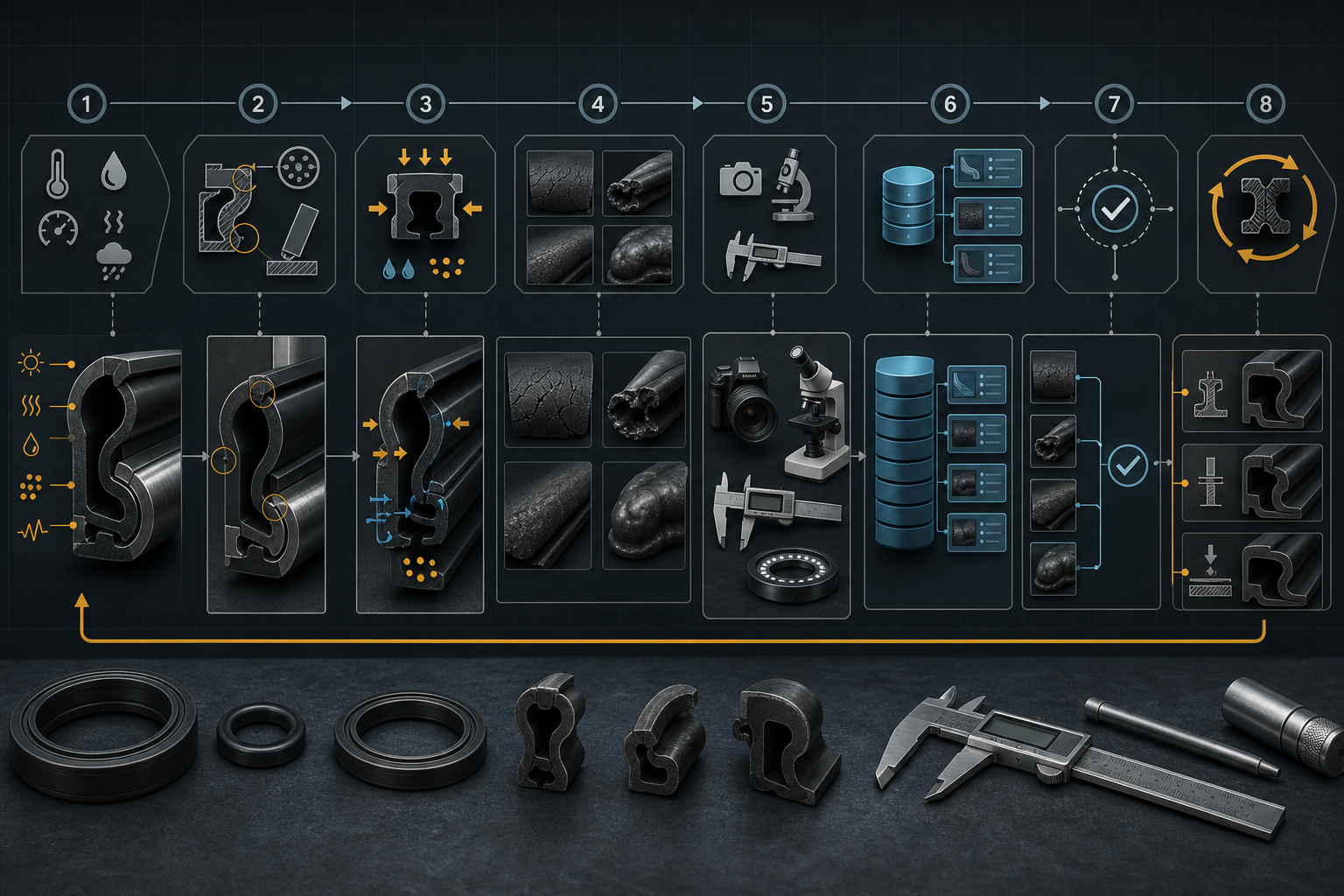
Evidence capture must begin before cleaning or cutting the failed seal. Overall photographs preserve distribution; macro photographs show position; microscopic images reveal crack roots, particles and torn edges; cross-sectional images show whether the damage is superficial or through the section. Before-cleaning and after-cleaning images should both be stored because residue and deposits may be part of the failure evidence.
Every image should include scale, orientation and location. Circumferential position, axial position, inner surface, outer surface, sealing lip, contact band, groove interface, fracture edge, deformed region and contaminated region should be described consistently. A crack recorded only as visible is weak evidence; a crack recorded as axial on the tensile side near the contact band is useful evidence.
Image artifacts must be controlled. Shadows may look like cracks, reflections may imitate surface film, oil residue may hide checking, and cleaning residue may be mistaken for chemical attack. The record should not show only the most dramatic region. Image quality directly controls diagnostic value. A photograph without scale, orientation and failure-location context should not be treated as complete evidence.
Crack, Tear and Fracture Morphology
Crack morphology must be interpreted through direction, location, depth and accompanying material state. Ozone cracking often appears as fine surface cracking on an exposed tensile surface. Thermal aging cracks usually appear with hardening, gloss loss, embrittlement or surface powdering. Fatigue cracks are more closely tied to cyclic bending, repeated compression, dynamic motion or stress concentration.
Radial cracks, circumferential cracks, surface checking and branched crack networks carry different implications. A circumferential crack on a compressed O-ring may suggest stress concentration or cyclic deformation, while random shallow checking on an exposed surface may point toward environmental aging. Surface checking is not equivalent to a through-crack, but it may become a leakage path after propagation.
Tears and installation nicks must be separated from service cracking. A tool cut often has a sharper edge, a directional origin and a location consistent with the assembly path. A fatigue crack usually shows progressive growth. Fracture-edge appearance, crack opening, root condition and crack-tip shape help distinguish overload, aging, embrittlement and mechanical initiation.
Cracks can form from material, environment, design stress and installation damage acting together. Microscopic examination, hardness mapping, elongation comparison, ozone exposure review, thermal-aging review, fractography, cross-section examination, crack-depth measurement, chemical compatibility review and motion history are all useful. Crack count alone is not a defensible root-cause conclusion.
The database should record crack direction, position, depth, distribution and accompanying material state. The conclusion should remain suspected until strain history, media exposure, hardness change and service age support one mechanism over competing explanations.
Extrusion, Nibbling and Pressure-Related Damage
Extrusion occurs when pressure drives elastomer into a clearance gap. The visible result may be local material displacement, back extrusion, gap bite, torn extrusion fragments or nibbling. Uniform extrusion around the circumference suggests a system-level pressure, clearance or stiffness issue. Local extrusion may point to eccentricity, misalignment, pressure direction, uneven groove support or local clearance variation.
High pressure, pressure spikes, pressure cycling, rapid reversal, thermal softening, low hardness, low modulus and failed anti-extrusion support can accelerate damage. The extruded edge often becomes thinner and weaker before it tears, producing rubber particles and reducing the effective seal cross-section. Leakage may begin after the material is no longer able to maintain contact pressure at the gap side.
Extrusion can be misread as cutting, wear or general tearing. A cut follows a tool or assembly path, abrasion follows relative motion, and extrusion follows pressure and clearance geometry. Verification should include clearance measurement, groove inspection, pressure history, temperature history, hardness verification, compression measurement, extrusion-depth measurement, counter-surface inspection, dynamic pressure testing and sectioned cross-sectional analysis.
Changing to a harder compound may reduce one extrusion mechanism but can introduce other problems such as poor low-temperature compliance or reduced sealing recovery. Corrective action must address the pressure profile, gap geometry, back-up ring condition, edge chamfer and material response together.
Swelling, Shrinkage and Chemical-Media Damage
Media-induced morphology begins when fluid, gas, solvent, coolant, fuel, steam, water-glycol or other exposure changes the elastomer network. Uniform swelling suggests broad absorption, while local swelling may indicate uneven contact, local heating, trapped liquid or contamination. Radial and axial swelling affect groove fill differently and may disturb compression ratio, friction and assembly fit.
Swelling is governed by compound polarity, crosslink density, filler system, temperature, concentration and exposure time. A swollen seal may overfill the groove, increase friction, extrude into a gap or lose dimensional control. Softening increases vulnerability to extrusion, wear and tearing. Surface tackiness, gloss loss, color change and adhesive transfer are useful supporting evidence but not final proof.
Shrinkage, hardening and embrittlement may occur when media extracts plasticizers or other migratory constituents. The same exposure can first swell a part, then leave it smaller or harder after volatile loss or leaching. Blistering, delamination and surface attack may indicate permeation, internal pressure or chemical degradation, but they must be compared with pressure, heat and cleaning history.
Chemical-media damage must be distinguished from thermal expansion, water absorption, cleaning residue and pressure-induced deformation. Verification should compare mass, volume, hardness, surface chemistry and cross-section condition. FTIR, TGA, DSC and controlled immersion comparison can support diagnosis, but short immersion tests cannot automatically represent long-term dynamic sealing.
Material compatibility cannot be judged by media name alone. Concentration, temperature, exposure time, pressure, cycling, contamination and actual seal geometry all affect the result. The database should record observed swelling, suspected media mechanism, competing explanations and confirmation status separately.
Wear, Abrasion, Compression Set and Permanent Deformation
Wear records the history of contact. Abrasive wear may show rough removal, scoring, embedded particles or directional scratches. Adhesive wear and polishing may form smooth contact bands, but a polished band is not automatically healthy. It may indicate excessive load, lubrication starvation or elevated friction.
Wear direction is diagnostic. Single-sided wear may indicate eccentricity, skew, shaft runout or axial misalignment. Circumferentially uneven wear may relate to installation distortion, poor lubrication or surface roughness. Wear debris can enter liquid, vacuum or precision-motion systems and create secondary contamination or accelerated wear elsewhere.
Compression set and permanent flattening reduce sealing force even when the surface appears intact. Long-term squeeze, high temperature, chemical relaxation, creep, stress relaxation, groove overfill and over-compression can all reduce rebound. Under-compression creates a different failure path by never generating adequate contact pressure in the first place.
Static compression set and dynamic wear require different judgment. One removes elastic recovery; the other removes material or changes the contact track. Evaluation should include contact-band measurement, surface roughness, hardness mapping, compression recovery, friction or torque testing, counter-surface inspection, wear-debris analysis and comparison with an unused part.
Installation Damage, Contamination and Secondary Morphology
Installation damage commonly appears at entry edges, groove corners, parting lines or tool-contact locations. Cutting during installation tends to show a sharp, directional feature. Twisting and rolling can create spiral wear, local thinning or abnormal contact bands. Overstretching may weaken the section before the seal enters service.
Foreign particles, embedded contamination, metal transfer, assembly debris, mold-release residue, cleaning residue and packaging fiber can become secondary morphology. A particle trapped at the interface may create a local leak path or indentation. Incompatible lubricant can cause swelling, softening or slip during assembly, creating a pattern that later looks like service damage.
Failure removal can create new scratches, tears and cuts. The database must distinguish primary failure morphology from secondary handling damage. When disassembly procedure, tooling or handling records are missing, uncertain features should remain observed or suspected rather than being assigned to operation with false confidence.
Morphology-to-Mechanism Diagnostic Logic
The database should separate morphology classification from mechanism classification. Surface cracks, deep cracks, circumferential cracks, local extrusion, uniform extrusion, nibbling, local swelling, uniform swelling, shrinkage, hardening, softening, polished wear bands, rough abrasion, compression flattening, blistering, embedded particles, installation cuts, torn edges, adhesive transfer and deposits are observed patterns.
Each record should include a primary visual descriptor, likely mechanism, alternative mechanism, supporting evidence, recommended test, functional concern, database tag and confidence level. For example, local swelling may suggest chemical exposure, but it may also reflect cleaning residue, trapped fluid or local heat. A circumferential crack may suggest ozone, thermal aging or strain concentration depending on position and surface state.
Unknown and unconfirmed must remain valid categories. Forcing a root cause too early corrupts the database and weakens corrective action. Root-cause confidence should increase only when morphology, service history, material condition and verification results converge. The database should preserve raw observation, not only the final conclusion.
Table II. Morphology-to-Mechanism Diagnostic Matrix
|
Observed morphology |
Primary hypothesis |
Alternative explanation |
Verification method |
Confidence level |
Database tag |
| Fine surface cracks | Ozone exposure | Heat, flex fatigue | Exposure and hardness review | Suspected | crack_ozone |
| Local extrusion | Gap overload | Installation cut | Clearance and section check | Suspected | extrusion_local |
| Uniform swelling | Media absorption | Thermal expansion | Mass and volume test | Observed | swelling_uniform |
| Polished wear band | Dynamic friction | Normal seating | Surface and torque review | Suspected | wear_polished |
| Embedded particles | Contamination | Disassembly debris | Particle and handling review | Observed | particle_embedded |
| Flattened section | Compression set | Over-compression | Section and rebound test | Suspected | compression_set |
This table summarizes diagnostic relationships. It supports the surrounding analysis but does not replace verification.
Application-Specific Failure Morphology
Hydraulic and pneumatic seals often emphasize extrusion, nibbling, pressure-cycle damage, abrasive wear and particle contamination. Rotary shaft seals emphasize lip wear, eccentric contact, heat, lubrication and shaft surface condition. Reciprocating seals add scoring, rolling, extrusion and dynamic friction. Each application requires motion-specific evidence capture.
Vacuum seals emphasize cracking, compression set, outgassing and particle shedding. Semiconductor equipment seals require attention to metal transfer, volatiles, particle release and chemical media. Battery and thermal-management seals require coolant compatibility, swelling, leakage and particle migration through pumps or narrow passages.
Medical and laboratory equipment add cleaning, sterilization and batch-traceability concerns. Chemical-process seals must connect morphology to media compatibility and process exposure. General industrial seals may tolerate broader cosmetic variation, but they still require classification when morphology affects sealing force, leakage, friction or maintenance frequency.
Verification, Testing and Confidence Ranking
Visual inspection and microscopy describe morphology, but they do not confirm chemical mechanism. Microscopy can reveal crack roots, wear direction, particle indentation and torn edges. Dimensional measurement and groove review show whether the observed deformation is compatible with the hardware condition.
Material-state tests add a second evidence layer. Hardness mapping, mass and volume comparison, compression-set testing, tensile or elongation testing, swelling ratio measurement, extractables analysis, FTIR or comparable material analysis, DSC, TGA and surface chemistry review can support or reject hypotheses about aging, extraction, swelling, oxidation or thermal exposure.
Functional and service tests close another part of the chain. Pressure testing and leak testing verify the sealing consequence but do not automatically identify the mechanism. Dynamic motion testing, counter-surface inspection, wear-debris analysis, thermal-aging review, ozone exposure review, installation audit and lubricant compatibility review help separate design, material, installation, media and maintenance causes.
The database should use at least three confidence states: observed, suspected and confirmed. Optional fields may include confidence score, evidence completeness, replication status, peer-review status and need for additional testing. Failure-analysis reports must separate observation, engineering inference and verified conclusion.
Table III. Failure Evidence Capture and Verification Guide
|
Evidence type |
Recording objective |
Key variable |
Suitable failure mode |
Required record |
Main limitation |
| Overall image | Distribution | Orientation | All failures | Scale and position | Low detail |
| Microscopy | Edge detail | Magnification | Crack, wear, residue | Location map | Small field |
| Cross-section | Internal state | Cut plane | Swelling, set, crack | Section direction | Destructive |
| Hardness map | Material state | Location | Heat, media, aging | Test method | Not root cause alone |
| Mass or volume | Media response | Baseline | Swelling, shrinkage | Exposure condition | Geometry dependent |
| Leak test | Functional result | Pressure, fixture | Sealing failure | Test condition | No mechanism proof |
This table summarizes diagnostic relationships. It supports the surrounding analysis but does not replace verification.
Database Governance, Searchability and Continuous Improvement
A morphology database requires controlled vocabulary. Crack, checking, tear and fracture cannot be used interchangeably without definition. Morphology taxonomy, material taxonomy, application taxonomy, failure-location coding, severity classification and evidence-completeness rules make records searchable and comparable.
Image naming, metadata requirements, revision control and duplicate-record control prevent the database from becoming an unstructured folder. Analyst training and peer review reduce classification variation. Synonym mapping helps search across common terms while preserving controlled categories.
The database should connect to supplier feedback, corrective-action linkage, trend analysis, recurrence tracking, preventive-maintenance linkage, 8D, CAPA, FRACAS, FMEA and design-change records. Record quality matters more than record count. Periodic review should update the taxonomy when repeated failures, new materials or new applications expose weaknesses in the classification system.
FMEA Risk Analysis
Design, material, manufacturing, assembly and operating conditions generate different failure morphologies by changing local stress, seal contact, compression, friction, media compatibility and particle state. A morphology database can supply historical evidence for FMEA, but the record must separate failure mode, cause, local effect and system effect. Unconfirmed root causes should remain visible in the database rather than being converted into fixed conclusions. Corrective action should address the verified mechanism, not merely the visible appearance.
The RPN values are illustrative engineering risk rankings, not field statistics or experimental results.
Table IV. Rubber Seal Failure Morphology FMEA
|
Failure mode |
Cause |
Local effect |
System effect |
Morphology evidence |
Detection method |
RPN |
Corrective action |
| Surface crack | Ozone or heat | Surface opening | Leak growth | Fine crack network | Microscopy | 168 | Control exposure |
| Deep crack | Fatigue or stress | Section rupture | Immediate leak | Through crack | Sectioning | 192 | Reduce strain |
| Extrusion | Clearance, pressure | Edge loss | Particles, leakage | Gap bite | Groove check | 189 | Revise groove |
| Wear | Debris, roughness | Contact loss | Friction, leak | Wear band | Surface review | 160 | Improve surface |
| Compression set | Heat, squeeze | Force loss | Static leak | Flattening | Recovery test | 175 | Change design |
| Swelling | Media uptake | Overfill | Friction, leak | Volume increase | Mass/volume | 196 | Verify material |
| Installation cut | Sharp edge | Local cut | Early leak | Tool-like mark | Assembly audit | 150 | Improve installation |
| Residue | Cleaner or media | Surface film | Contamination | Deposit film | FTIR/EDS | 132 | Control cleaning |
This table summarizes diagnostic relationships. It supports the surrounding analysis but does not replace verification.
Conclusion
A rubber seal failure morphology database is not a photo archive. It is a structured evidence system that connects observed damage with material, design, manufacturing, assembly, media and operating condition. Cracks, extrusion, wear, compression set and media swelling require different observation and verification logic.
Morphology and root cause must be recorded separately. Any unverified cause should remain suspected or unconfirmed until evidence supports it. The value of the database is stronger trend recognition, better supplier communication, improved maintenance decisions and more disciplined recurrence prevention. Final judgment must return to sealing function, leakage risk, contamination risk, maintenance efficiency and long-term reliability.
Engineering FAQ
Q:What is a rubber seal failure morphology database?
A:It is a structured engineering evidence system that records visible damage, location, service condition, material identity, verification evidence and corrective action. It is not a collection of photographs. A useful record links the observed morphology to suspected mechanism, confidence level and confirmed root cause when available. The database should also preserve uncertain or incomplete cases instead of forcing a conclusion.
Q:Why should morphology and root cause be recorded separately?
A:Morphology is what is observed; root cause is what is supported by evidence. A crack may come from ozone, fatigue, thermal aging, installation damage or media attack. Recording the crack as the cause destroys diagnostic value. Separate fields for observed morphology, suspected mechanism and confirmed root cause allow later review when new evidence appears.
Q:Can a crack pattern prove that a seal failed because of ozone?
A:No. Ozone cracking has recognizable tendencies, such as fine surface cracks on exposed tensile surfaces, but similar patterns may involve heat, flexing, surface stress or chemical exposure. Confirmation requires strain direction, exposure history, hardness or elongation change and environmental records. The crack pattern is evidence, not proof.
Q:How can extrusion be distinguished from installation damage?
A:Extrusion normally follows pressure direction and clearance geometry. It often appears as gap bite, nibbling or displaced material near the pressure side. Installation damage usually follows a tool path, groove edge, twist or insertion direction. Groove measurement, pressure history, sectioning and assembly review are needed before the distinction is reliable.
Q:What evidence is useful for confirming chemical swelling?
A:Useful evidence includes mass change, volume change, hardness shift, surface tackiness, cross-section change, media record and controlled immersion comparison. FTIR, TGA, DSC or other material analysis may support the conclusion. Test conditions should match actual medium, temperature, concentration, pressure and exposure time as closely as practical.
Q:Why can compression set cause leakage even without visible cracks?
A:Compression set reduces elastic recovery and lowers contact pressure. A seal may look intact but no longer presses strongly enough against the mating surface. This can create leakage without fracture. Diagnosis should include cross-section comparison, rebound evaluation, groove fill, service temperature, compression history and material condition.
Q:How should failure photographs be captured for database use?
A:Images should include overall distribution, local macro detail, microscopic evidence where needed, scale, orientation and failure location. The record should state whether the image shows the lip, contact band, groove interface, inner diameter, outer diameter or back-pressure side. Before-cleaning and after-cleaning views are useful when residue or particles matter.
Q:Which tests are useful for confirming the suspected failure mechanism?
A:Useful tests include microscopy, sectioning, hardness mapping, compression-set measurement, mass and volume comparison, FTIR, DSC, TGA, SEM-EDS, residue analysis, immersion comparison, pressure testing, leak testing, dynamic wear testing and installation review. No single test confirms every mechanism. The selected test must match the competing hypotheses.
Q:How can a failure morphology database support FMEA and preventive maintenance?
A:The database shows which morphologies recur under specific materials, applications, media, pressure ranges or installation conditions. These patterns can update FMEA rankings, improve corrective actions and guide preventive maintenance. The limitation is that database frequency is not automatically field probability unless exposure population and reporting bias are understood.
Post time: Sep-07-2026