
Executive Summary
Rubber seal cleanliness is not produced by washing alone. It is established earlier, at the mold parting line, then preserved or damaged through trimming, cleaning, drying, packaging and assembly. Flash, trim chips, torn-edge fragments and residue are not cosmetic details when they sit near a sealing lip, groove-contact surface or particle-sensitive flow path.
The core risk is twofold. Under-trimming leaves flash, trim tails and loose fragments that can interfere with assembly or become mobile particles. Over-trimming can be equally serious because it removes useful cross-section, cuts the lip, thins the edge or creates a crack starter. A visually neat part may therefore carry a worse functional risk than a part with a stable, non-functional flash remnant.
Visual inspection, a single leak test and a single particle count each see only one part of the risk chain. Reliable release requires linking defect source, particle migration, seal-interface disturbance, cleaning effectiveness and functional verification. Trimming quality must be treated as seal-geometry control and contamination control, not as a final appearance operation.
Rubber Seal Manufacturing and Defect-Boundary Architecture
The quality boundary starts in the mold. The cavity defines the intended cross-section; the parting line defines where rubber can escape if closure, venting, compound flow or mold condition drifts. Vents, gates, flow-front regions and insert interfaces often become flash origins because local pressure and clearance differ from the main cavity.
A trimming defect must be judged by where it sits. A feature on the outer non-contact edge does not carry the same consequence as the same feature on a lip edge, inner diameter, groove-contact face or vacuum-facing surface. Functional sealing surfaces require continuity of compression and contact width; particle-sensitive surfaces require low shedding and clean handling even when they do not seal directly.
Mold wear, incomplete closure and blocked venting change both flash height and flash-root shape. Thin residual film can fold into an interface, while thick flash can become a trimming burden that encourages tool damage. The release decision must therefore consider location, direction, morphology, detachability and functional zone rather than visual size alone.
Table I. Rubber Seal Trimming Zones and Quality Functions
|
Seal zone |
Defect source |
Quality function |
Trimming risk |
Consequence |
Verification focus |
| Lip edge | Parting line, cut path | Continuous contact | Notch, thinning | Leakage, crack start | Magnified edge review |
| Groove face | Residual film, chips | Stable seating | Embedded debris | Local lift | Dimensional and particle check |
| Inner diameter | Flow front, tail | Media boundary | Loose projection | Particle migration | Extraction and microscopy |
| Outer diameter | Mold mismatch | Assembly fit | Rolled burr | Installation drag | Visual and fit check |
| Packaging surface | Handling, tray | Clean storage | Fiber transfer | Recontamination | Post-packaging check |
This zone-based view prevents a common error: applying one flash limit to every surface. Functional position and detachability define risk more accurately than apparent defect size.
Flash, Burr and Trimming-Defect Formation
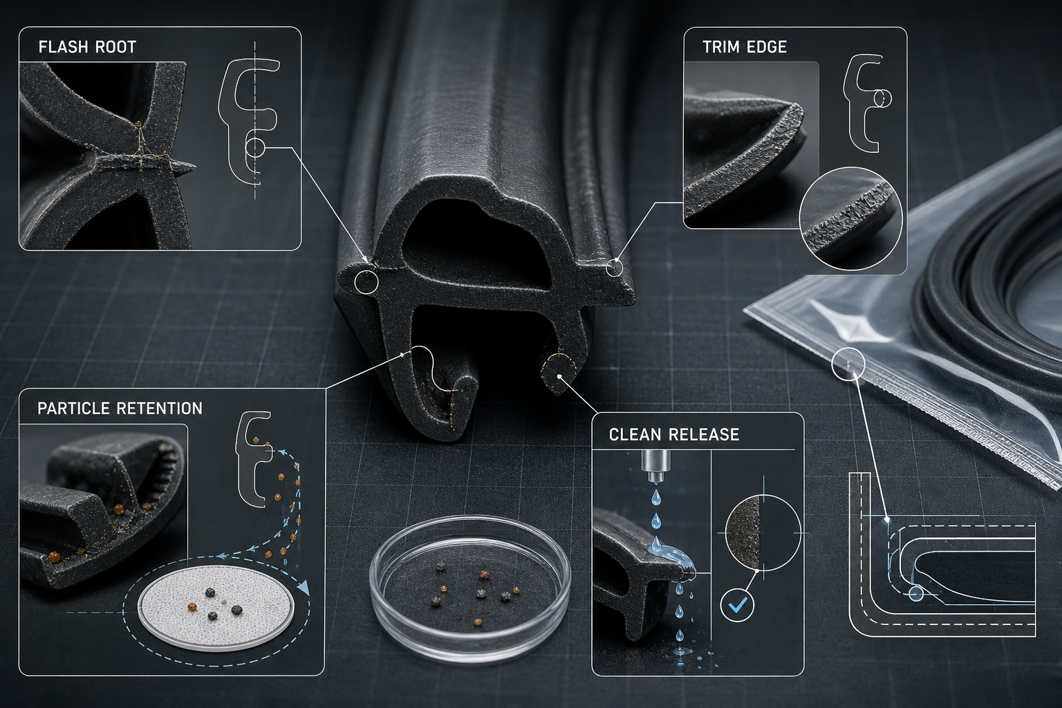
Flash is molded overflow. A burr is a raised or rolled edge created by removal. A trim tail is incomplete removal, while a torn edge or notch is trimming damage. These features may look similar in a quick visual check, but their origins and consequences differ. Flash points to mold or molding drift; burrs and tears point to tool condition, support, feed or operator variation.
Mold mismatch, mold wear, excessive pressure, incomplete closure and overflow enlarge the flash root. The root matters because it is the transition from controlled seal geometry to unwanted material. If it is thick, trimming may leave a step. If it is thin and stretched, trimming may pull material away from the intended lip and create a weak edge.
Tool sharpness, blade clearance, feed speed and part support determine whether trimming separates flash or damages the seal. A dull tool can roll material instead of cutting it. Excess clearance can create a ragged edge. Poor support lets the elastomer stretch, producing local thinning or a surface tear. Manual trimming adds variation through angle, lighting, magnification and fatigue; automated trimming adds fixture and recognition errors.
The engineering target is not absolute removal of every visible trace. On a functional lip, an over-cut notch may be more damaging than a small stable remnant outside the contact zone. Trimming acceptance should ask whether the defect can shed, fold into the interface, reduce contact width or initiate cracking under pressure, motion or temperature cycling.
Trimming Methods and Process-Window Control
Manual, blade and punch trimming can produce controlled edges when the part is supported and the tool remains sharp. Their weakness is sensitivity to clearance, cutting angle and operator judgment. Thin lips, small cross-sections and soft compounds reduce the margin between flash removal and edge damage.
Cryogenic deflashing reduces manual variation by embrittling flash and breaking it away, but it does not guarantee a low-particle surface. Broken fragments, media carryover and roughened flash roots may remain. Tumble and abrasive deflashing can remove projections, yet collision and rubbing may create powder, transferred debris or surface abrasion.
Robotic, laser-assisted, plasma-assisted and vision-guided trimming can improve repeatability when fixture position and part geometry are stable. Their limitation is that visual acceptance is not particle-release assessment. A camera can classify an edge as clean while embedded debris or a weakened flash root remains.
A real process window combines compound hardness, geometry, flash morphology, cleanliness target and downstream cleaning capability. Cycle time is secondary. The chosen method must control both edge geometry and releasable contamination within the intended application boundary.
Table II. Trimming, Cleaning and Particle-Risk Matrix
|
Process factor |
Primary effect |
Secondary effect |
Failure mode |
Measurement |
Limitation |
| Blade sharpness | Separates flash | May cut lip | Notch, torn edge | Microscopy | Support variation |
| Punch clearance | Defines shear | Compresses lip | Rolled burr | Dimensional check | Fixture sensitivity |
| Cryogenic media | Breaks flash | Leaves fragments | Rubber powder | Extraction test | Not cleanliness proof |
| Tumble contact | Removes projections | Transfers debris | Abrasion | Particle count | Collision variation |
| Rinse quality | Removes debris | Can redeposit | Residue | Membrane analysis | Procedure dependent |
| Drying condition | Removes liquid | May age surface | Residue or change | NVR, visual check | Hidden moisture |
The process route must be evaluated as a chain. A trimming method that removes flash efficiently can still fail if it creates debris that the cleaning and packaging system cannot control.
Edge Damage, Seal Geometry and Functional Integrity
A seal functions by controlled deformation. Compression, squeeze, groove fill, contact width and recovery define the barrier. Trimming damage changes those variables locally. A notch concentrates stress; local thinning changes recovery; a rough torn edge can become a crack start or wear source in dynamic service.
Residual flash creates the opposite problem: extra material where the gland expects a controlled profile. A folded flash tail or trapped chip can lift part of the contact band. This may create a narrow leakage path without obvious gross misassembly. The same residue can also become a particle source after compression relaxes or flow begins.
Initial pressure-hold tests may pass before a cut grows or a fragment migrates. Functional acceptance should therefore consider defect depth, direction, continuity, proximity to the contact band and detachability. Trimming defects only reveal their real consequence when evaluated under actual compression, motion, pressure and medium exposure.
Particle Generation, Retention and Migration
Particle sources include flash fragments, trim chips, rubber powder, torn-edge fragments, filler release, mold-release residue, cleaning residue, packaging fiber, glove debris, metal particles and abrasive carryover. Soft elastomer fragments may compress and migrate; hard metallic or abrasive particles may scratch surfaces, jam valves or damage optical and precision mechanisms.
Particles remain where geometry, tack, roughness or static charge allows retention. Flash roots, torn edges, microcracks, rough trim surfaces, groove-contact faces and packaging folds can all hold debris beyond the reach of a visual check. Cleaning may remove loose debris while leaving embedded particles or future shedding sites.
Migration occurs during vibration, unpacking, groove insertion, compression, pressure fluctuation, pump-down and fluid circulation. In vacuum equipment, particles can move toward chambers and optical areas. In liquid systems, flow can carry debris toward valves, pumps, microchannels or filters. A low count after one extraction does not prove that the trimmed edge lacks cracks, weak flash roots or later shedding potential.
Cleaning, Drying and Clean-Handling Control
Cleaning after trimming must remove both visible and invisible contamination: residual flash, rubber powder, trim chips, mold-release residue, oils, cleaner residue, abrasive carryover and packaging fiber. Aqueous, solvent, spray and ultrasonic methods apply different chemical and mechanical loads, so compatibility with the compound is part of cleanliness control.
Ultrasonic and spray cleaning can release debris from flash roots, but poor filtration, rinse quality or part spacing can redistribute particles. Solvents may remove oils but can swell, harden, extract or roughen some elastomers. Cleaning must therefore be validated against material response, not selected only by apparent cleaning strength.
Drying is also a release boundary. Residual moisture or solvent can cause outgassing, residue transfer or packaging contamination. Excessive heat may change surface condition or recovery. Clean handling must then preserve the result through gloves, tools, trays, double-bagging, storage and transport. Cleaned is not a release standard unless the method, rinse, drying and packaging controls are defined.
Application-Specific Cleanliness and Sealing Risks
Semiconductor and vacuum equipment emphasize particles, outgassing, metal ions and vacuum leakage. A defect on a vacuum-facing edge may shed during pump-down or disturb local compression. Verification may combine edge microscopy, extraction, residue or ion testing, outgassing assessment and helium leak testing; no single test covers all risks.
Precision fluidic equipment is sensitive to particles entering microchannels, pump seats, valve clearances and analytical regions. Hydraulic and pneumatic systems focus on spools, throttling orifices, filters and sliding surfaces. Battery and thermal-management equipment add concern for coolant passages, pumps and valves, where fragments may migrate long after assembly.
Medical and laboratory equipment require residue control, traceability and lot consistency. Chemical-process seals must balance particle control with media compatibility and sealing function. General industrial seals may accept wider cosmetic variation, but not defects that impair installation or contact pressure. Different applications require different release logic because the migration path and consequence are different.
Inspection, Metrology and Cleanliness Verification
Visual inspection finds gross flash, trim tails and obvious damage. Magnified inspection and microscopy reveal torn edges, flash roots, local thinning and residual films. Automated optical inspection improves consistency, but it still evaluates appearance. Sampling area, lighting, angle and classification rules strongly affect the result.
Dimensional inspection, cross-section measurement, flash-height measurement, edge-defect measurement and surface-roughness review connect appearance to geometry. They show whether trimming changed lip thickness, edge radius, contact width or groove profile. Their limitation is that geometry does not identify particle chemistry or future shedding behavior.
Cleanliness verification requires extraction and residue methods. Rinse-and-count testing, filter-membrane analysis, particle-size distribution, gravimetric analysis, chemical composition analysis, ion testing and non-volatile residue testing identify releasable contamination and likely source. Results depend on extraction medium, agitation energy, rinse volume, membrane pore size and handling procedure.
Functional tests add another layer. Helium leak testing verifies selected leakage paths, pressure-hold testing shows gross sealing response, compression testing checks contact behavior and outgassing testing supports vacuum use. None is a substitute for the others. Release should combine edge morphology, dimensions, particle evidence, residue analysis, packaging inspection and functional sealing evidence.
Table III. Rubber Seal Cleanliness and Functional Verification Guide
|
Test or inspection |
Objective |
Key variable |
Detectable issue |
Stage |
Limitation |
| Visual inspection | Find gross defects | Light, angle | Large flash, tail | After trimming | No particle proof |
| Microscopy | Review edge | Magnification | Notch, tear, root | First-piece, audit | Limited view |
| Flash-height check | Quantify projection | Gauge method | Excess flash | Molding, trimming | Location dependent |
| Rinse-and-count | Measure particles | Fluid, agitation | Loose chips, powder | After cleaning | Method dependent |
| Membrane analysis | Classify particles | Pore size | Rubber, metal, fiber | Release audit | Test contamination risk |
| NVR or ion test | Detect residue | Solvent, sensitivity | Cleaner residue, ions | Clean validation | No geometry data |
| Helium leak test | Verify leak path | Pressure, fixture | Functional leakage | Assembly test | No cleanliness proof |
| Compression test | Check contact | Squeeze, groove | Geometry disturbance | Qualification | No particle data |
Verification is strongest when methods overlap without pretending to measure the same thing. Cleanliness evidence, geometry evidence and sealing evidence must be combined.
Material, Mold and Trimming-Process Selection
Material selection changes trimming response but does not remove process risk. NBR, EPDM, FKM, FFKM, HNBR, silicone, polyurethane, PTFE-based elements and filled compounds differ in hardness, tear resistance, tack, filler behavior, compression recovery, compatibility and outgassing. Higher hardness may fracture flash cleanly in one route but create sharper debris in another.
Low-flash or low-extractable compounds can reduce specific risks, but low flash does not automatically mean low particle release. Filled materials may improve mechanical behavior while increasing attention to exposed filler at torn or cut edges. Cleanroom-grade material claims still require validation under the actual trimming, cleaning, drying and packaging route.
Mold precision, parting-line condition, vent design, surface finish, trimming-tool quality and cleaning compatibility must be selected together. Mold accuracy reduces trimming burden; tool precision limits edge injury; cleaning compatibility controls residue and debris removal. No material, mold or trimming method is universally best for every seal.
Process Control, Traceability and Maintenance
Trimming quality cannot rely on final inspection alone. Incoming material verification, batch traceability, molding-parameter records and mold-maintenance records show whether the part entered trimming with a stable defect boundary. First-piece approval and parting-line inspection catch flash drift before a full batch is processed.
Trimming-tool inspection, sharpness control, operator training and in-process sampling control the finishing step. A blade may still remove flash while gradually creating more powder or micro-tears. Manual trimming requires defined light, magnification and acceptance criteria. Automated trimming requires fixture and calibration records.
Cleaning, drying, particle-test, packaging and environmental records extend traceability beyond the trimming station. Rework criteria must separate repairable non-functional residue from irreversible lip cuts, deep notches, cracks, thinning or embedded hard particles. When leakage or contamination occurs, records should connect the event to material, mold, tool, cleaning, packaging and assembly conditions.
FMEA Risk Analysis
The risk chain begins when mold parting, venting, closure force, compound flow or mold wear creates flash, offset or residual film. Trimming then either converts that boundary into a controlled edge or creates tearing, notching, thinning or debris. Particles from flash removal, tool wear, abrasive contact, cleaning residue or packaging can migrate into the seal interface or process system. Geometry defects disturb compression and contact pressure; mobile particles threaten cleanliness, valves, pumps, optics and vacuum chambers.
The RPN values are illustrative engineering risk rankings, not field statistics or experimental results.
Table IV. Rubber Seal Trimming and Cleanliness FMEA
|
Failure mode |
Cause |
Local effect |
System effect |
Detection |
RPN |
Corrective action |
| Excessive flash | Mold wear, poor closure | Projection | Assembly interference | Flash check | 168 | Maintain mold |
| Residual burr | Dull blade | Raised edge | Contact lift | Microscopy | 150 | Replace tool |
| Torn edge | High feed | Crack start | Delayed leakage | Magnified review | 180 | Reduce feed |
| Edge notch | Over-trimming | Stress concentration | Leak path | Section check | 192 | Revise path; scrap severe |
| Rubber powder | Fracture or abrasion | Loose debris | Fluid contamination | Extraction | 175 | Validate cleaning |
| Metal particles | Tool wear | Hard debris | Surface damage | Membrane analysis | 196 | Control tool wear |
| Cleaning residue | Poor rinse | Surface film | Outgassing, transfer | NVR or ion test | 144 | Improve rinse |
| Packaging fiber | Tray or bag | External debris | Recontamination | Packaging check | 132 | Control packaging |
| Interface debris | Chip in groove | Local lift | Functional leakage | Leak and compression | 189 | Clean groove |
| Weak verification | No recheck | Undetected drift | Repeat failure | Record audit | 160 | Requalify after change |
The FMEA table should not be treated as a fixed document. Its risk priorities should be revised when process data, cleaning validation, return analysis or maintenance findings show that a trimming or cleanliness risk is more severe, more frequent or less detectable than originally assumed.
Conclusion
Rubber seal trimming controls both edge geometry and latent particle sources. Excessive flash, residual burrs, over-cut lips, rubber powder, cleaning residue and packaging fiber arise from different mechanisms and require different controls. A clean-looking seal is not necessarily low-particle, and a particle-tested seal is not automatically functionally sound.
A defensible release decision treats mold condition, material response, trimming, cleaning, drying, packaging and assembly as one quality system. Visual condition, dimensional evidence, edge morphology, particle extraction, residue testing, packaging control and functional sealing evidence must be interpreted together. Trimming is the boundary between manufacturing variation and precision-sealing reliability.
Engineering FAQ
Q:Why does rubber seal trimming quality affect cleanliness?
A:Trimming creates or exposes particle sources at the same boundary later contacting grooves, fluids or clean assemblies. Flash roots, cut edges and torn surfaces can retain debris after cleaning. Control must therefore combine edge inspection with post-clean extraction and packaging checks.
Q:What is the difference between flash, burrs, trim tails and torn edges?
A:Flash is molded overflow. Burrs are raised edges created during removal. Trim tails are residual projections. Torn edges are damaged elastomer boundaries. They should be classified by origin, location and detachability, not grouped as one visual defect.
Q:Can a seal with visible flash still be functionally acceptable?
A:Yes, but only when the flash is outside the functional sealing region, stable and non-shedding. Flash on a lip, groove-contact face or particle-sensitive surface requires stricter judgment because it can interfere with compression or migrate.
Q:Why can over-trimming be as dangerous as under-trimming?
A:Over-trimming can remove contact width, thin the lip or create a notch. These defects may grow under pressure, motion or temperature cycling. Under-trimming leaves debris; over-trimming may permanently damage the sealing geometry.
Q:How do rubber particles migrate from a seal into a precision system?
A:Particles release during vibration, unpacking, groove insertion, compression, pump-down or liquid circulation. They can then move into valves, pumps, microchannels, optical regions or vacuum chambers. Packaging and assembly handling are part of particle control.
Q:Can visual inspection prove that a rubber seal is particle-free?
A:No. Visual inspection finds gross flash and obvious damage, but not sub-visible particles, embedded debris or future shedding sites. Particle extraction, membrane analysis and packaging inspection are required when release risk matters.
Q:How should cleaning and drying be selected after rubber seal trimming?
A:Selection should follow compound compatibility, debris type, geometry, cleanliness target and packaging method. Strong cleaning can also redistribute particles or damage surfaces. Drying must remove liquid without changing material state.
Q:Which tests are useful for verifying seal cleanliness?
A:Useful methods include rinse-and-count extraction, membrane analysis, particle sizing, chemistry, ion contamination and non-volatile residue testing. For vacuum use, outgassing may matter. These methods should be paired with edge and functional checks.
Q:What records should be maintained for trimming, cleaning and packaging control?
A:Maintain material lot, mold condition, trimming-tool status, operator or program, first-piece approval, cleaning batch, drying condition, particle results, packaging lot and storage records. These records make leakage or contamination traceable to the actual process boundary.
Post time: Sep-07-2026