
Executive Summary: Why Refill Does Not Prove Seal Re-Wetting
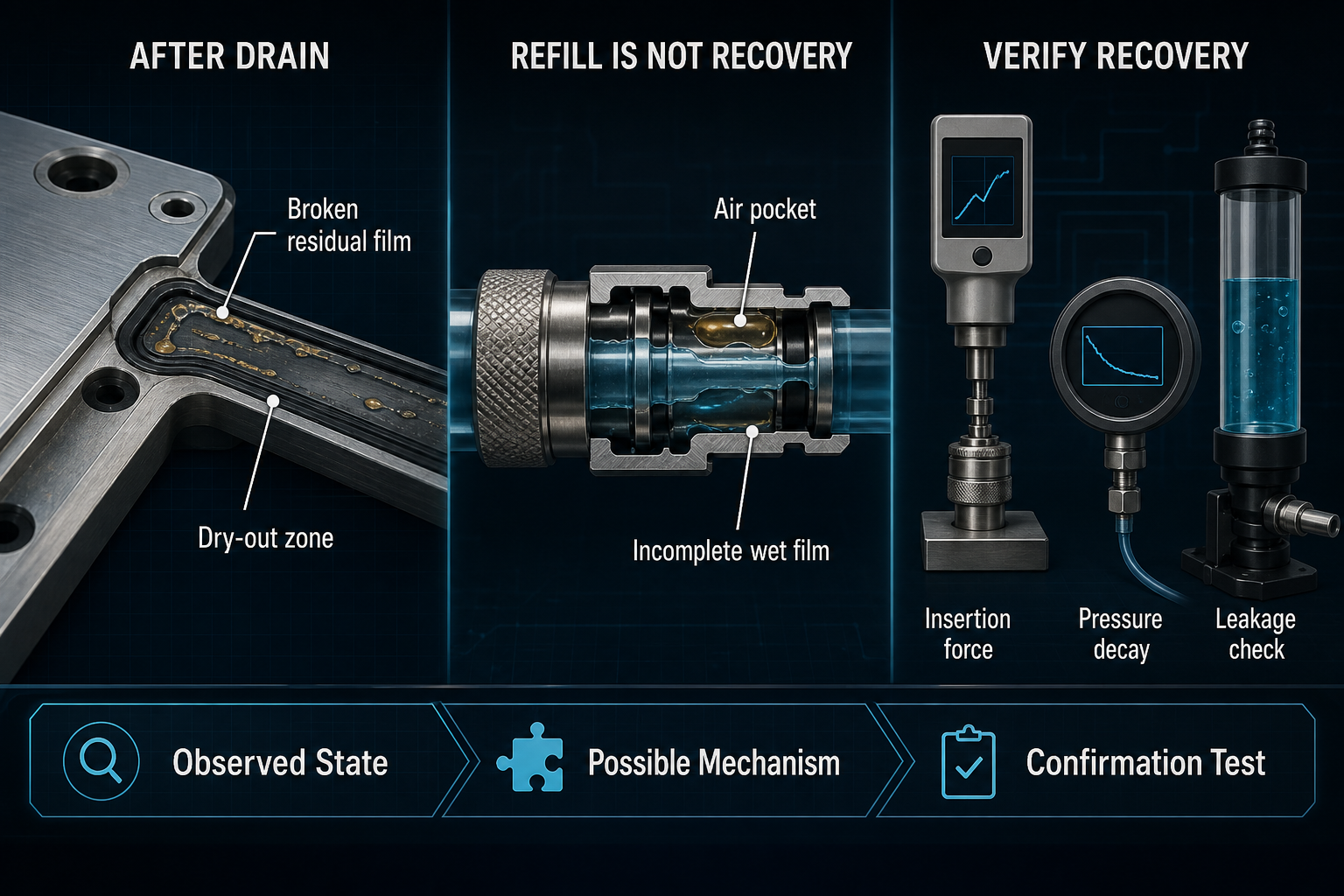
After a liquid-cooling system is drained, the seal interface does not necessarily preserve the same liquid film that existed during normal operation. Coolant may leave grooves, quick connectors, valve seats and compressed contact zones unevenly. Some locations may retain a thin residual coolant film, while other areas undergo local dry-out or become separated from liquid by air entrapment. When the system is refilled, coolant availability is restored at the system level, but the compressed seal interface may still need time and flow history to rebuild stable surface wetting.
Seal re-wetting is therefore not the same phenomenon as coolant absorption, seal swelling or residue dissolution. It is a local interface recovery process governed by surface tension, contact angle, capillary action, seal compression, coolant chemistry and venting efficiency. The practical consequence is not limited to visible leakage. Re-wetting state can change friction force, insertion force, sliding response, contact pressure distribution, pressure decay behavior and the interpretation of leakage verification. A system that appears full of coolant is not automatically a system whose seals are fully re-wetted.
Drain-Induced Seal Interface Changes: Residual Film, Dry-Out and Air Entry
Draining a liquid-cooling system creates a non-uniform interface condition. Coolant leaves open flow passages first, but the liquid held inside seal grooves, valve seats, coupling pockets and horizontal sections may remain, migrate or evaporate more slowly. Gravity, capillary action and surface tension can pull residual coolant toward low points or trapped corners. At the same time, air can enter the interface from vented passages or maintenance openings, interrupting what had been a continuous liquid film.
The word drained should therefore not be read as completely dry. A seal may be wet on one side, dry at a sliding lip, and exposed to discontinuous residue at a gland shoulder. Drain time, ambient temperature, airflow, system orientation and coolant volatility all change the degree of dry-out. A polymer that has absorbed coolant internally may still present a partially dry surface, while a seal with visible surface residue may not be truly re-wetted. These distinctions matter because surface wetting, material absorption and residue are different evidence categories.
Table 1 – Seal Interface Conditions After Liquid-Cooling System Draining
| Observed Condition | Possible Cause | Seal-Interface Effect | Potential Risk | Required Confirmation |
| Thin residual film | Incomplete drainage | Partial lubrication | Unstable friction | Surface inspection |
| Discontinuous residue | Evaporation/additives | Patchy wetting | False dry state | Residue check |
| Local dry-out | Air exposure | Higher adhesion | Insertion damage | Friction test |
| Air pocket | Venting path | Film interruption | Test bias | Venting evidence |
| Coolant trapped in groove | Low point/dead leg | Delayed exchange | Contamination hold-up | Drain audit |
| Cleaning residue | Maintenance process | Altered contact angle | Poor re-wetting | Compatibility check |
Re-Wetting After Refill: From Coolant Arrival to Continuous Liquid Film
Refill begins with liquid arrival, but liquid arrival is only the first step. Coolant may reach a manifold, connector or gland-adjacent cavity while the compressed seal contact remains partly isolated. For the interface to recover, liquid must enter narrow contact regions by pressure difference, capillary action or local motion. Surface tension and contact angle determine whether the coolant spreads across the seal surface or remains as separated droplets and channels.
Compression can help sealing yet restrict re-wetting access. A tightly compressed elastomer may resist liquid entry into the contact band until pressure cycling, sliding motion or pre-circulation redistributes coolant. High points and dead zones may also retain air, and air entrapment can break wet-film continuity even after liquid surrounds the component. Low-flow refill, fast inlet pressure rise, poor venting or an unfavorable system posture can leave a seal in a mixed wet and dry state.
Stable re-wetting should be viewed as a sequence: liquid arrival, surface wetting, continuous liquid-film formation, air removal and stable operating condition. Coolant additives, contamination, cleaning residue and surface-energy differences between EPDM, FKM, HNBR, NBR, silicone, polyurethane, PTFE-based designs or coated polymers can alter this sequence. None of these variables proves leakage by itself, but each can change the recovery path that must be verified.
Friction, Insertion Force and Contact Pressure During Re-Wetting Recovery
A reduced or interrupted liquid film changes the mechanical behavior of the seal before leakage is visible. Static friction and start-up friction can increase when an O-ring, lip seal or coupling seal is partially dry. In quick connectors, valve stems and sliding interfaces, insufficient pre-wetting may increase insertion force or actuation force. The immediate risk is not only operator difficulty; high friction can roll, twist, nick or scuff the seal during reassembly.
Re-wetting often reduces friction, but excessive liquid or an incompatible assembly lubricant can create different problems, including local hydraulic resistance, contamination or residue formation. Contact pressure is still created by squeeze, gland geometry and hardware stiffness, not by the liquid film itself. However, the wetting state changes how surfaces slide, adhere and release under that contact pressure. Air trapped at the interface can also distort pressure decay or leakage verification because the measured response may reflect compressible gas, unstable wetting or delayed liquid migration rather than a stable leak path.
A short-term microleak after refill may indicate incomplete re-wetting, but it may also indicate seal damage, contamination or poor venting. Conversely, leakage that disappears after pre-circulation does not prove long-term material compatibility. The evidence must separate measured leakage, possible wetting mechanism, engineering hypothesis and confirmation test.
Table 2 – Re-Wetting State and Seal-Performance Consequences
| Re-Wetting Condition | Friction or Contact Effect | Possible Failure Mode | Observable Symptom | Verification Method |
| Incomplete wetting | Higher start friction | Seal twist | High insertion force | Force trace |
| Delayed film | Stick-slip | Surface scuffing | Irregular motion | Cycle test |
| Air-interrupted film | Unstable contact | False leak result | Pressure drift | Venting check |
| Dry insertion | High adhesion | Cut or roll | Assembly damage | Visual inspection |
| Excess lubricant | Hydraulic/residue effect | Contamination | Delayed leakage | Compatibility review |
| Stable re-wetting | Lower friction | Reduced transient leak | Repeatable response | Pressure decay |
Material and Surface Compatibility: Re-Wetting Is Not Swelling or Absorption
Material names alone do not define re-wetting recovery. EPDM, FKM/FPM, HNBR, NBR, silicone, polyurethane and PTFE-based sealing designs differ in surface energy, coolant absorption, desorption behavior, compression set tendency and sensitivity to additives. Even within one material family, compound formulation, fillers, coating, cure state and molded surface condition can change contact angle and residue behavior.
Seal swelling is a dimensional or volume response caused by fluid interaction with the polymer. Coolant absorption is transport into the material. Seal re-wetting is the rebuilding of a surface liquid film at the interface. These events may occur together, but they should not be interpreted as the same evidence. A slightly swollen seal may still have a poorly wetted surface after dry exposure; a surface that looks wet may still carry incompatible residue or cleaning film.
Coolant base fluid, inhibitors, corrosion products, cleaning residue and maintenance lubricant can all modify wetting behavior. Low temperature may increase viscosity and slow liquid penetration into narrow interfaces, while higher temperature may accelerate evaporation or residue concentration during draining. Long dry exposure can make the first refill state different from new assembly. For this reason, compatibility must be verified for the actual coolant, seal geometry, exposure history and maintenance process.
Verification Sequence: Draining, Refill, Venting and Leakage Evidence
A reliable verification sequence begins before the system is drained. Engineers should record baseline flow, pressure, leakage status, coolant formulation, batch condition and contamination evidence. During drain, the process should document drain time, system posture, vent path, ambient temperature and air exposure. After drain, seal surfaces, grooves and connector seats should be inspected for residual coolant, local dry-out, residue, scratches or adhesion marks where access permits.
Refill should then be controlled rather than treated as a simple fill-to-volume operation. Inlet pressure, fill rate, venting route, degassing method, pre-circulation time and circulation flow should be recorded. Verification should include static pressure hold, pressure decay, liquid leakage verification and, where relevant, gas leakage testing. For quick connectors or moving valves, insertion force, sliding force or actuation force provides a mechanical signal that wetting recovery may be incomplete.
Test timing is critical. A pressure decay result immediately after refill may not match the result after venting and pre-circulation. Temperature and coolant viscosity also affect wetting and measurement response. Therefore, one leakage result should not be converted into a long-term compatibility conclusion unless the drain-and-refill cycle, venting state and post-test inspection support that interpretation.
Table 3 – Recommended Verification Sequence for Seal Re-Wetting Recovery
| Test Stage | Main Control | Measurement | Failure Question | Key Limitation |
| Baseline | Flow/pressure | Leak status | Was it stable before drain | No re-wetting data |
| Controlled drain | Time/posture | Residual liquid | Where can dry-out occur | Access limited |
| Surface check | Cleanliness | Residue/damage | Is surface altered | May require disassembly |
| Controlled refill | Fill rate/pressure | Liquid arrival | Is refill repeatable | Arrival not wetting |
| Venting/pre-cycle | Air removal | Pressure/force trend | Is film stable | Timing sensitive |
| Pressure decay | Hold condition | Decay curve | Leak or gas effect | Needs correlation |
| Leak verification | Liquid/gas method | Leak evidence | Is leakage real | May be transient |
| Repeat cycle | Same procedure | Change trend | Does recovery degrade | Longer program |
Engineering Controls: Making Re-Wetting a Controlled Maintenance State
Engineering control begins with design. Flow paths and interfaces should allow draining and venting without leaving unrecognized pockets beside seal grooves. High points, low points and horizontal mounting zones should be reviewed for air entrapment and residual coolant retention. Dead zones near seals should be minimized where possible, or at least included in maintenance and verification procedures.
Maintenance controls should define maximum air exposure where relevant, inspection criteria for residue and damage, and whether a seal may be reused after a drain-and-refill cycle. Pre-wetting and assembly lubricant can reduce dry insertion risk, but they are not substitutes for venting or pre-circulation. Lubricant must be compatible with the coolant and seal material, and excessive lubricant can create residue, hydraulic effects or diagnostic confusion.
Refill controls should specify a sequence that promotes wetting recovery: controlled fill, venting, degassing, pre-circulation, functional motion where applicable and final leakage verification. First restart after maintenance should be treated as a recovery condition, not ordinary operation. Repeated drain-and-refill cycles should be included in validation when the service model requires frequent maintenance or connector replacement.
FMEA Risk Analysis: Failure Modes Created by Unstable Re-Wetting
The FMEA below treats unstable seal re-wetting as a local interface risk, not as a universal material failure. No numerical RPN is assigned because severity and occurrence depend on seal structure, coolant formulation, drain time, temperature, pressure, venting efficiency and maintenance procedure. The purpose is to connect failure mode, evidence and control action without inventing universal limits.
Table 4 – FMEA for Seal Re-Wetting Recovery After Drain-and-Refill Cycles
| Failure Mode | Cause | Local Effect | System Effect | Detection Method | Control Action |
| Incomplete seal re-wetting | Poor liquid access | Patchy film | Transient leak | Force/leak test | Pre-wet and pre-cycle |
| Air trapped at interface | Weak venting | Film break | False decay result | Venting evidence | Improve vent route |
| Residual coolant evaporation | Long air exposure | Residue/dry zone | High friction | Surface check | Limit exposure |
| Excessive drying | Hot airflow/time | Adhesion | Assembly damage | Insertion force | Replace or re-wet |
| Incompatible lubricant | Wrong assembly aid | Residue/swelling | Leak or sticking | Compatibility test | Approved lubricant |
| Seal twist/damage | Dry reassembly | Local cut | Immediate leak | Visual check | Controlled assembly |
| Incomplete venting | High-point air | Compressible pocket | Unstable test | Pressure trend | Defined venting |
| Repeated cycle degradation | Service history | Surface change | Reliability drift | Cycle testing | Reuse limits |
| Contaminated seal reuse | Residue/debris | Poor contact | Delayed leak | Inspection | Replace seal |
| False leakage result | Unstable wetting | Ambiguous path | Wrong decision | Repeat test | Stabilize condition |
Conclusion: Re-Wetting Must Be Verified, Not Assumed
Draining a liquid-cooling system can change the seal wetting state even when the seal material remains mechanically intact. Refill restores coolant to the system, but it does not prove immediate restoration of a continuous liquid film at every compressed interface. Reliable engineering judgment must consider drain degree, residual coolant, dry-out, coolant arrival timing, air entrapment, venting efficiency, material surface compatibility, friction force, insertion force, contact pressure, pre-circulation, pressure decay, leakage verification and seal reuse history.
The correct question is not whether coolant has entered the system. The correct question is whether the seal interface has reached a stable, verified wetting condition under the same mechanical and fluidic state in which it must operate. Until that evidence exists, seal re-wetting recovery remains an engineering hypothesis, not a proven condition.
FAQ
Q:Does refilling a liquid-cooling system automatically re-wet every seal?
A:No. Refill confirms that coolant has been introduced, not that every compressed seal interface has rebuilt a continuous liquid film. Local geometry, trapped air, contact pressure, coolant viscosity and surface condition can delay or interrupt seal re-wetting.
Q:Why can a seal remain partially dry after the system has been refilled?
A:A seal can remain partially dry when air blocks a contact region, when flow bypasses a dead zone, or when surface tension prevents coolant from spreading across a low-energy or contaminated surface. Liquid arrival near the seal is not the same as stable surface wetting.
Q:Is seal re-wetting the same as seal swelling?
A:No. Seal swelling is a material volume or dimensional response to fluid exposure. Seal re-wetting is the restoration of a surface liquid film at the interface. A swollen seal can still have unstable surface wetting, and a wetted surface does not prove acceptable swelling behavior.
Q:Can insufficient re-wetting increase insertion or sliding force?
A:Yes, especially in quick connectors, valve stems and sliding seals. Reduced liquid film can raise start-up friction, adhesion or stick-slip. The result may be higher insertion force, seal rolling, surface scuffing or assembly damage before visible leakage appears.
Q:How should air trapped near a seal be removed after refill?
A:Air removal should be handled by a defined venting and pre-circulation procedure matched to the system layout. High points, dead zones and horizontal interfaces need special attention. The procedure should be confirmed by pressure stability, flow response and leakage verification, not assumed from fill volume.
Q:Should seals be pre-wetted before liquid-cooling system assembly?
A:Pre-wetting can reduce dry assembly friction when it is compatible with the coolant, seal material and maintenance process. It does not replace venting or leak testing. Any pre-wetting fluid or assembly lubricant should be qualified for residue, swelling, contamination and friction behavior.
Q:Can a seal be reused after the system has been drained?
A:Reuse should be evidence-based. The seal may have experienced dry-out, residue, compression set, twisting, scratches or contamination during maintenance. Reuse requires inspection and functional verification under relevant pressure and wetting conditions; appearance alone is not enough.
Post time: Sep-10-2026