
Executive Summary
Surface transfer and adhesive wear in rubber seals are interface-evolution problems, not simple material defects. They develop when seal compound, counterface material, contact pressure, speed, lubrication, temperature and contamination combine to create local adhesion and shear. Rubber may transfer to a shaft or sleeve, while metal, coating fragments, lubricant residue or contamination may transfer back onto the seal surface.
A transfer film can be beneficial when it stabilizes friction, but it can also become unstable, detach and generate debris. Adhesive wear cannot be confirmed from a black band, glossy region or dark smear alone. It must be distinguished from abrasion, chemical attack, thermal degradation and installation damage. Surface transfer should be treated as an interface-evolution phenomenon that requires tribological evidence, not as a visual defect with a single automatic diagnosis.
Contact Architecture and Tribological Boundary Conditions
A rubber seal operates against a tribological system, not an isolated surface. The contact may involve a dynamic lip on a rotating shaft, a reciprocating rod, a sleeve, a bore, a groove wall or a static sealing zone that still experiences micro-motion. The real contact area is only a fraction of the apparent contact band, and local pressure is shaped by lip geometry, squeeze, clearance, shaft runout, eccentricity, misalignment and housing stiffness.
Counterface condition strongly affects transfer tendency. Surface roughness that is too high may cut or plough the seal, while a surface that is too smooth may reduce lubricant retention and increase adhesive junction formation. Hardness, coating integrity, machining lead and texture direction control whether the seal sees stable sliding, boundary lubrication or local dry friction. Rotary seals, reciprocating seals and static joints therefore cannot be judged by the same surface rule.
Lubricant film behavior is central. A stable film separates asperities and reduces adhesion, while boundary lubrication exposes the rubber to local shear and heat. Dry start, intermittent motion, poor lubricant supply, contaminated oil or temperature-driven viscosity loss can shift a seal from mild transfer to adhesive damage. Evaluation must record seal material, counterface, motion type, speed, pressure, temperature, lubricant and clearance together.
Surface Transfer and Adhesive-Wear Mechanisms
Adhesive wear begins at real-area contacts where asperities, rubber surface chains and counterface features form local junctions. Molecular adhesion, mechanical interlocking and high local shear can stretch the rubber surface, smear polymer across the contact and detach small fragments. Because elastomers are viscoelastic, the response depends on time, temperature, frequency, filler structure and local strain history rather than hardness alone.
Surface transfer may form a thin film on the shaft, sleeve or rod. In some cases this film lowers friction by creating a more compatible sliding layer. In other cases it becomes unstable: sections of the film thicken, tear, reattach, roll into debris or create adhesive patches. These patches can raise local contact pressure, disturb lubricant flow and trigger stick-slip. Frictional heat may then soften the seal or harden and oxidize the surface, depending on compound and exposure.
Counterface transfer can reverse the damage direction. Metal pickup, coating fragments, hard oxide, ceramic debris or polymer sleeve material may adhere to the seal lip and act as a new abrasive or adhesive site. The same rubber compound can show stable transfer on one shaft finish and severe adhesive wear on another because surface energy, coating adhesion, lubricant chemistry and operating temperature all change the junction strength.
Morphology, Failure Path and Functional Consequences
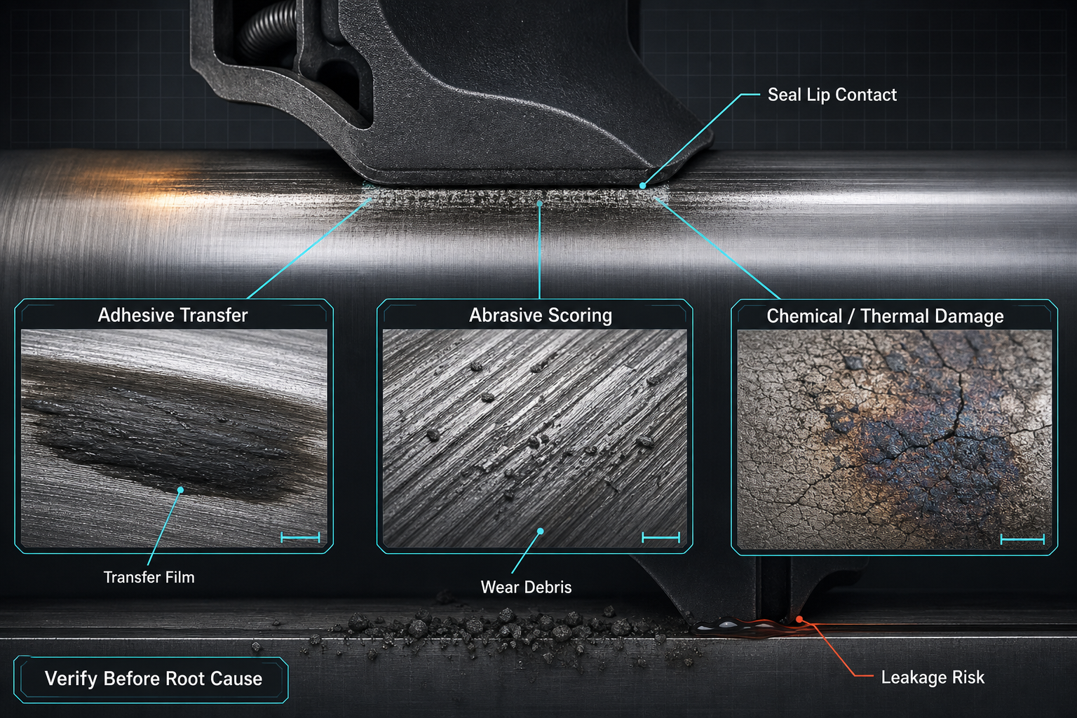
Common morphology includes smearing, glossy transfer film, dark transfer bands, local pickup, adhesive patches, torn rubber fragments, polished contact bands, surface tearing, local thinning and debris accumulation. On the counterface, engineers may see coating transfer, scoring, grooving, ploughing or pitting. Each feature needs a location record: lip edge, contact band, shaft track, groove wall, lubricant path or debris zone.
A transfer band changes function when it modifies friction or contact geometry. A raised adhesive patch may create a local high spot, redistribute contact pressure and open a small leakage path next to it. A polished band may show stable sliding, but it may also indicate frictional heating or lubricant starvation. Torn fragments and loose debris can contaminate hydraulic, pneumatic, lubrication or cooling circuits and accelerate subsequent wear.
Stick-slip is especially damaging because it converts unstable friction into torque fluctuation, noise, vibration and cyclic leakage. Local material removal reduces effective lip section and may alter radial load. A roughened counterface then becomes a secondary driver of abrasive wear. Color, gloss, dark deposits and stripes are preliminary evidence only; they may also come from oxidation, media residue, contamination, thermal decomposition or installation damage.
Table I. Surface-Transfer and Adhesive-Wear Morphology
|
Morphology |
Location |
Possible mechanism |
Alternative cause |
Concern |
Verification |
| Smearing | Seal lip | Polymer shear | Lubricant residue | Friction rise | Microscopy |
| Dark band | Counterface | Transfer film | Oxidation, dirt | Leak risk | Chemistry check |
| Adhesive patch | Contact band | Local pickup | Thermal deposit | Pressure shift | Profilometry |
| Torn fragments | Lip edge | Adhesive tearing | Installation nick | Debris | Fracture review |
| Scoring | Shaft track | Hard pickup | Abrasive particle | Wear acceleration | Surface scan |
| Coating transfer | Seal face | Coating loss | Media staining | Seal damage | Elemental analysis |
Material, Counterface, Lubrication and Thermal Effects
NBR, HNBR, EPDM, FKM, FFKM, silicone, polyurethane, PTFE-based elements, filled elastomers and low-friction compounds differ in polarity, surface energy, viscoelastic response, filler exposure and thermal behavior. None is universally resistant to surface transfer. A compound that performs well against hardened steel may behave differently against stainless steel, chrome plating, nickel coating, ceramic coating, polymer sleeves, composites or treated aluminum.
Counterface roughness has an optimum range for each system. High asperities can plough the seal and produce abrasive wear that is misread as adhesive tearing. Extremely smooth surfaces may fail to retain lubricant and can promote boundary contact. Machining direction and shaft lead may pump lubricant away from the lip or concentrate shear. Coating adhesion is also critical because delaminated coating fragments can become both transfer material and abrasive debris.
Lubricant viscosity, supply stability, additive package, contamination and temperature define the sliding regime. Boundary lubrication creates more real contact and higher adhesive risk than mixed-film operation. Frictional heat may soften, harden, char or make the rubber tacky. Thermal cycling and media exposure can change surface energy, swelling behavior and friction response. Low-friction compounds reduce one risk but do not eliminate transfer if surface, load or lubricant conditions are wrong.
Table II. Tribological Factors and Transfer-Wear Risk
|
Factor |
Interface effect |
Secondary effect |
Failure mode |
Control |
Limit |
| Contact pressure | Higher shear | Heat rise | Adhesive patch | Lip load control | Geometry dependent |
| Speed | Film stress | Temperature | Stick-slip | Speed limit | Duty dependent |
| Roughness | Asperity contact | Debris | Abrasion or transfer | Finish control | Needs surface data |
| Coating | Surface chemistry | Pickup | Delamination | Coating spec | Bond critical |
| Lubricant | Film stability | Additive effect | Dry contact | Supply control | Ages in service |
| Misalignment | Uneven band | Local heating | Lip thinning | Alignment check | Assembly sensitive |
Verification, Testing and Failure-Analysis Logic
Failure analysis should begin with controlled visual inspection, magnified inspection and microscopy, but photographs do not prove adhesive wear. Surface profilometry, roughness measurement, contact-band measurement and counterface inspection reveal whether the track has raised transfer film, ploughing, scoring, coating loss or local wear. Hardness mapping and comparison with an unused seal help identify thermal or chemical changes that could mimic adhesive damage.
Friction or torque measurement, temperature measurement, pressure and leakage testing, dynamic rotary testing and reciprocating testing connect surface evidence to functional behavior. Wear-debris collection, particle microscopy, lubricant analysis, transfer-film thickness assessment, FTIR or comparable chemistry and elemental analysis can identify what moved between surfaces. However, chemistry identifies composition, not automatically the sequence by which the transfer formed.
Evidence should be classified as observed, suspected, confirmed, inconclusive or not evaluated. Observed means the morphology is directly recorded. Suspected links the morphology to a plausible mechanism. Confirmed requires supporting tests or repeat evidence. Disassembly may create new tears, scratches or transfer marks, so the unused seal, failed seal, counterface and lubricant sample should be preserved together where possible.
Table III. Verification and Evidence Classification Guide
|
Evidence/test |
Objective |
Key variable |
Detects |
Status |
Limit |
| Microscopy | Morphology | Magnification | Smear, tear | Observed | No mechanism alone |
| Profilometry | Surface shape | Track location | Raised film | Suspected | Needs baseline |
| Chemistry | Composition | Sampling site | Transfer material | Confirmed support | Not sequence proof |
| Torque test | Function | Speed, load | Stick-slip | Suspected | Many causes |
| Leak test | Sealing result | Pressure | Leak path | Observed | No root cause |
| Unused compare | Baseline | Same lot | Wear change | Confirmed support | May vary by batch |
Application Risks and Engineering Control
Rotary shaft seals often show circumferential transfer bands, lip polishing, torque increase and heat-driven debris. Reciprocating hydraulic and pneumatic seals may show directional smearing, stick-slip, rod scoring and intermittent leakage. Pump, compressor, gearbox and electric-motor seals add lubricant aging, shaft finish and temperature as major variables. Vacuum, battery thermal-management, medical and laboratory equipment seals add contamination sensitivity and cleanability concerns.
Engineering control must combine material, counterface, lubrication, geometry, assembly and operating condition. Counterface finish, hardness, coating adhesion, shaft lead and machining direction should be specified with the seal design, not after failure. Groove and lip geometry should distribute contact pressure without forcing local dry contact. Lubricant selection must consider viscosity, supply, additives, cleanliness and compatibility.
Process control is equally important. Alignment, eccentricity, installation tools, break-in procedure, contamination exclusion, temperature limits and supplier traceability should be documented. Corrective action should not default to changing the compound. In many cases the more effective fix is improved counterface preparation, lubricant control, contact-pressure correction, debris exclusion or preservation of post-failure evidence for mechanism verification.
FMEA Risk Analysis: Seal Surface Transfer and Adhesive Wear
Seal and counterface form a real tribological contact in which adhesion, shear, frictional heat and transfer-layer instability may create material loss. Surface transfer can affect friction, contact pressure, debris generation and leakage, but morphology, mechanism, local effect and system effect must be recorded separately. Unverified adhesive-wear assumptions must not be written as confirmed root cause. The RPN values are illustrative engineering risk rankings, not field statistics or experimental results.
Table IV. FMEA Risk Analysis
|
Failure mode |
Cause |
Local effect |
System effect |
Detection |
RPN |
Action |
| Unstable film | Heat, shear | Patch growth | Torque rise | Track review | 168 | Control film |
| Rubber pickup | Adhesion | Shaft deposit | Leakage | Counterface scan | 180 | Surface/lube fix |
| Metal transfer | Coating loss | Lip damage | Debris | Elemental test | 190 | Improve coating |
| Stick-slip | Boundary contact | Vibration | Noise, leak | Torque test | 160 | Lubrication control |
| Overheating | High friction | Softening | Wear acceleration | Temperature check | 175 | Reduce load/speed |
| Misclassification | Weak evidence | Wrong fix | Repeat failure | Review evidence | 200 | Confirm mechanism |
Conclusion
Surface transfer and adhesive wear are results of continuous interface evolution. A transfer layer may reduce friction, but it may also trigger stick-slip, heat accumulation, debris generation and leakage when it becomes unstable. Morphology must be interpreted against competing explanations such as abrasion, chemical damage, thermal damage and installation damage.
Reliable control requires the seal material, counterface, lubrication, contact pressure, speed, temperature and contamination environment to be evaluated together. Observed transfer is not a confirmed root cause. Corrective action must be based on traceable evidence, comparative testing and the actual operating condition rather than a visual impression or a single material property.
Engineering FAQ
Q:What is surface transfer in a rubber-seal contact?
A:Surface transfer is the movement of material from one contacting surface to another during sliding or micro-motion. Rubber may smear onto a shaft, or counterface material may attach to the seal. It is an observed interface phenomenon, not a root cause by itself. Confirmation requires location, morphology, counterface evidence, lubricant condition and operating history.
Q:How is adhesive wear different from abrasive wear?
A:Adhesive wear comes from local adhesion, shear and material detachment at real contact junctions. Abrasive wear comes from hard asperities or particles that cut, plough or scratch the surface. The two can coexist, especially when adhesive debris becomes abrasive. Microscopy, profilometry and debris analysis help separate the mechanisms.
Q:Can a dark transfer band prove that adhesive wear occurred?
A:No. A dark band may be rubber transfer, oxidized residue, lubricant deposit, thermal decomposition, media staining or external contamination. Color and gloss are preliminary evidence only. Engineers should inspect the counterface, analyze transferred material and compare the failed seal with an unused part before confirming adhesive wear.
Q:Why can stick-slip accelerate seal damage and leakage?
A:Stick-slip creates alternating sticking and rapid sliding at the contact. This can raise local heat, disturb lubricant film, create torque fluctuation and produce periodic changes in contact pressure. The result may be noise, vibration, debris and intermittent leakage. Testing should record friction or torque over time, not only final leakage.
Q:How do counterface roughness and coating condition affect material transfer?
A:Roughness controls asperity contact and lubricant retention. A rough surface may plough the rubber, while an overly smooth surface may increase boundary contact. Coating loss can transfer hard fragments to the seal and create secondary wear. Surface finish, coating adhesion and machining direction should be verified with the seal design.
Q:Which tests are useful for confirming adhesive wear?
A:Useful tests include microscopy, surface profilometry, roughness measurement, contact-band measurement, torque or friction testing, temperature measurement, counterface inspection, transfer-film chemistry, elemental analysis, lubricant analysis and debris microscopy. No single test proves the mechanism. Confirmation requires agreement between morphology, material evidence and operating history.
Q:Can changing the rubber compound alone solve a transfer-wear problem?
A:Sometimes it helps, but it is rarely sufficient by itself. Transfer wear depends on compound, counterface, lubricant, contact pressure, speed, temperature, alignment and contamination. Changing the elastomer without correcting roughness, coating failure, lubricant starvation or eccentric loading may only move the failure mode to another surface or service interval.
Post time: Sep-08-2026