
Executive Summary
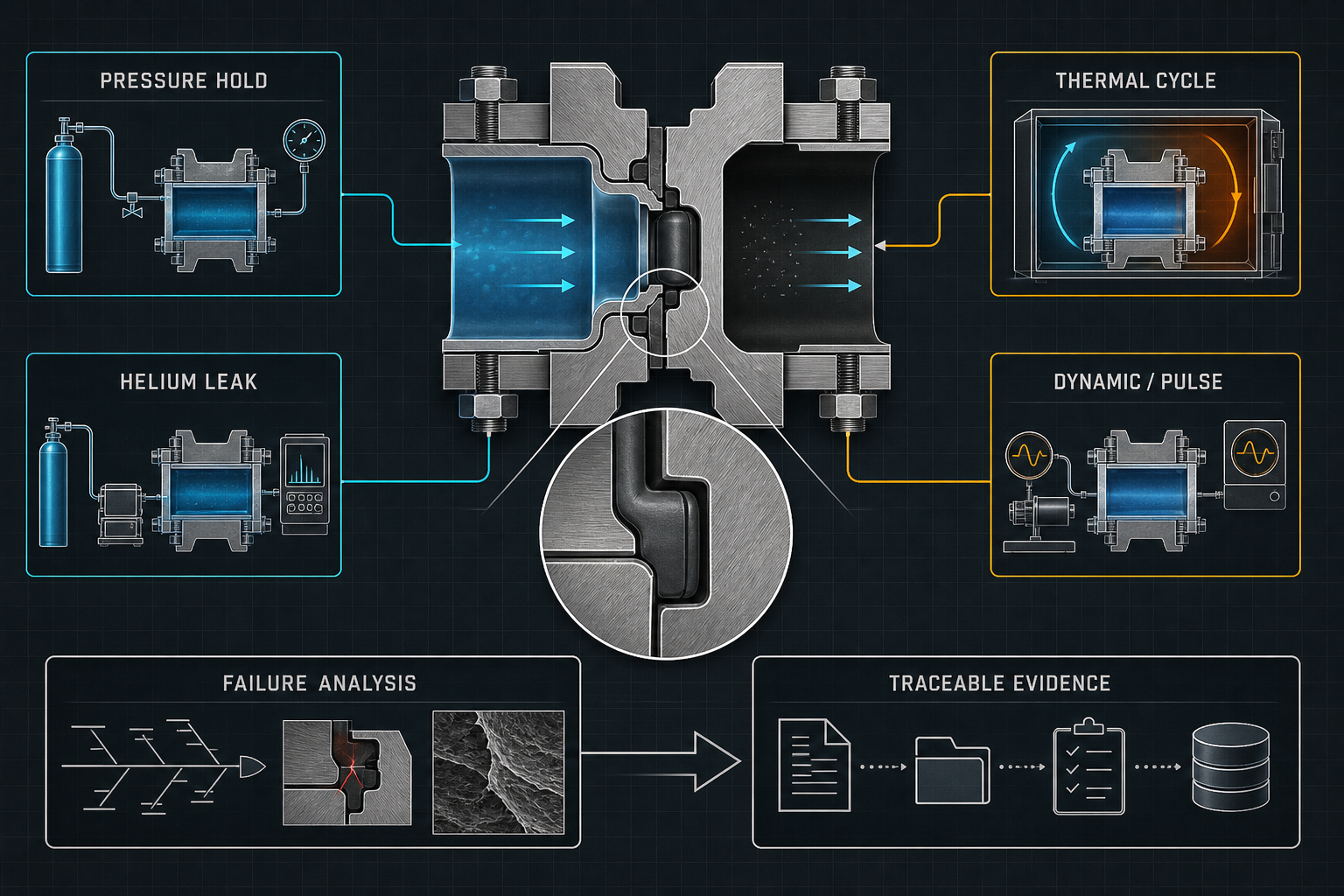
Seal validation engineering demonstrates that a sealing system retains its required function under defined pressure, temperature, medium, motion and time conditions. The objective is not merely to record whether a leak was detected, but to identify the challenged failure mechanism, detection sensitivity and service boundary.
Pressure-hold, helium, thermal-cycle and dynamic tests answer different questions. A seal can pass one and fail another because pressure retention, micro-leakage, thermal movement, chemical degradation and wear are separate physical problems. Evidence must be assigned to its stage: design validation proves the design; process validation proves assembly consistency; production inspection checks a unit or batch; maintenance verification checks restoration; and life-cycle validation examines accumulated stresses.
The reliable evidence chain is test purpose, condition, result, failure analysis and corrective action. A pass means the defined test found no failure under its stated conditions; it does not prove reliability outside them.
Pressure-Hold and Hydrostatic Testing
A pressure-hold test applies internal pressure, allows the assembly and fixture to stabilize, and observes pressure change or visible leakage. Hydrostatic testing uses liquid; pneumatic testing uses gas and introduces greater compressibility, temperature sensitivity and stored-energy considerations.
Pressure decay must be interpreted with test volume, fixture compliance, trapped air, ambient temperature and stabilization in view. A falling signal may result from leakage, temperature change, fixture expansion or unresolved gas compression. The pressure-time trace is more informative than a final reading. The test can expose large through-leaks, loose connections, installation errors, cracks and inadequate pressure retention.
It cannot establish micro-gas leakage, thermal-cycle life, leakage during movement, vacuum-side outgassing, cleanliness, chemical compatibility or low-temperature start-up performance. Pressure, hold time and allowable drop must be selected for the structure, medium, temperature, volume and acceptance basis.
Table I: Seal Validation Method Comparison
|
Method |
Main purpose |
Detectable failure |
Sensitivity characteristic |
Test medium |
Main limitation |
Validation stage |
| Pressure-hold | Verify pressure retention | Large through-leak; loose joint; crack | Moderate; volume and time dependent | Liquid or gas | Weak for micro-leaks and life claims | Production; design baseline |
| Hydrostatic | Check pressure boundary strength | Body crack; gross leakage; deformation | Good for pressure boundary defects | Water or approved liquid | Moisture and trapped-air effects | Design; proof testing |
| Pneumatic | Check gas pressure containment | Gross leakage; joint failure | Temperature and compressibility sensitive | Air or inert gas | Stored energy; stabilization required | Design; process |
| Helium mass spectrometer | Locate small through-leaks | Fine leak path; weld or seal defect | High; mode and background dependent | Helium tracer gas | Does not prove cycling, chemistry or cleanliness | Design; troubleshooting |
| Pressure-decay | Quantify pressure change | Leakage or unstable boundary | Depends on volume, time and resolution | Gas or liquid | Fixture expansion can mimic leakage | Process; production |
| Vacuum rate-of-rise | Assess vacuum pressure behavior | Air ingress; outgassing contribution | System-volume and background dependent | Vacuum with defined gas condition | Cannot isolate every source without controls | Design; maintenance |
| Dynamic leakage | Validate sealing during motion | Wear; stick-slip; motion leakage | Profile dependent; requires cycling | Actual or representative medium | Not interchangeable with static testing | Design; life-cycle |
The methods are complementary rather than interchangeable. A pressure result describes pressure retention in a defined setup, while helium and dynamic results describe different leakage pathways and operating states.
Helium Mass-Spectrometer Leak Detection
Helium leak detection introduces tracer gas and measures detector response associated with a flow path. In vacuum mode, the part is evacuated and helium is applied to accessible external locations. In sniffer mode, the detector samples helium near an externally pressurized part. Mode, fixture, application sequence and response time determine the meaning of the result.
Calibration, background control and surface condition are essential. Residual helium, contaminated surfaces, porous materials, fixture leakage or excessive application can mislead. Record detector condition, calibration, temperature, sample configuration, background, helium application and acceptance basis.
Helium testing suits micro through-leaks, vacuum defects, weld or braze discontinuities, seal-interface channels and fine leakage in valves, manifolds and tubing. It does not prove post-cycle leak-tightness, dynamic life, chemical compatibility, cleanliness, outgassing limits or full service life. Any leak-rate value must be tied to mode, sensitivity, background and acceptance rule.
Thermal Cycling and Pressure-Cycle Testing
Thermal cycling challenges the dimensional and mechanical balance of the interface. Expansion and contraction can change compression, contact pressure, alignment and clearance. Repeated exposure can accumulate compression set, stress relaxation, hardening, softening or permanent deformation. The critical result is often not the initial leak rate but the change in leakage after the specified thermal history.
The test record should include minimum and maximum temperature, heating and cooling rate, dwell time, cycle count, internal pressure, test medium and leakage results before and after cycling. These records allow a failure to be associated with thermal movement rather than assigned incorrectly to the material name alone.
Pressure-pulse testing applies repeated pressure excursions and can expose fatigue at seal interfaces, joints, diaphragms, fittings or pressure boundaries. Minimum and maximum pressure, pressure rise and fall rate, pulse frequency, cycle count, medium and post-test seal condition should be recorded. One completed thermal cycle or one pressure pulse sequence is evidence of response to that sequence; it is not a universal life proof.
Table II: Test Condition Selection Matrix
|
Service condition |
Main failure risk |
Recommended test |
Key parameter |
Required record |
Test limitation |
| Static pressure | Gross leakage; joint movement; crack | Pressure-hold plus visual inspection | Pressure, volume, stabilization and hold period | Pressure-time curve; fixture ID; sample ID | Limited micro-leak sensitivity |
| Vacuum service | Air ingress; outgassing; fine leak | Helium leak and rate-of-rise test | Vacuum level, mode, background and response | Calibration; background; helium application | Does not prove dynamic or chemical life |
| Thermal cycling | Compression change; relaxation; interface movement | Pre/post leak test with thermal cycling | Temperature limits, rates, dwell and cycles | Temperature history; medium; leak results | One cycle is not long-term life proof |
| Pressure pulsing | Fatigue; joint loosening; seal extrusion | Pressure-pulse cycling and repeat leak test | Pressure range, ramp rate, frequency and cycles | Pulse trace; cycle count; teardown notes | Profile may not represent field duty |
| Chemical exposure | Swelling; hardening; cracking; extraction | Exposure or immersion plus dimensional and leak checks | Actual medium, concentration, temperature and duration | Mass, hardness, dimensions and photos | Material test is not full-system validation |
| Dynamic movement | Wear; friction; motion leakage | Actuation, rotary or reciprocating leakage test | Speed, stroke, force, cycles and medium | Motion profile; torque/force; leak trend | Static pass cannot substitute |
| Cleanliness-sensitive use | Particles; ions; volatile residues | Extractables, outgassing, particle and rinse analysis | Sampling method, volume, temperature and limits | Blank, sample, method and result traceability | Leak pass is not cleanliness pass |
The test condition should reproduce the dominant service stress whenever practical. Pressure, temperature, medium and motion are not background details; they are the variables that drive the failure mechanism.
Dynamic, Chemical and Cleanliness Validation
Dynamic seal testing is required when the interface actuates, rotates, reciprocates or repeatedly opens and closes. The test should reproduce the relevant speed, stroke, force, pressure, temperature and medium while recording leakage and, where useful, torque or actuation force. Wear tracks, friction changes and intermittent leakage may remain invisible in a static pressure test.
Chemical compatibility testing evaluates swelling, softening, hardening, cracking, extraction, mass change, dimensional change and loss of elasticity. Immersion or exposure testing is a controlled material or component screen; it is not automatically a life test for a complete assembly exposed to motion, pressure pulses, temperature changes and installation stress.
Cleanliness validation addresses a different evidence class. Extractables testing, outgassing testing, particle inspection, rinse-water analysis, ionic or residue analysis and surface inspection determine whether the seal introduces contamination within the defined process boundary. Leakage passage and cleanliness passage must not be treated as the same acceptance decision. Post-test teardown connects the measured result to the actual surface, crack, wear, residue or deformation morphology.
Building a Validation Plan
A practical plan starts with service conditions and failure modes, then selects the minimum set of tests that can challenge them. The sequence should define samples, configuration, medium, pressure, temperature, motion, cycle count, detection method, acceptance basis, retest rule, instrument identification and traceability before testing begins.
- • Define service conditions and identify the dominant failure modes.
- • Select test methods and state their detection boundaries.
- • Prepare representative samples and record configuration and batch.
- • Calibrate instruments and establish a baseline leakage result.
- • Apply thermal, pressure, chemical or dynamic stress.
- • Repeat leakage testing, inspect the surface and conduct teardown.
- • Link the result to corrective action and release criteria.
Table III: Validation Workflow and Evidence Chain
|
Validation stage |
Test action |
Evidence produced |
Decision point |
Follow-up action |
| Design review | Map service envelope to seal structure and failure modes | Requirement matrix and risk list | Are all dominant mechanisms challenged? | Add or revise test coverage |
| Baseline leakage | Run defined pressure, vacuum or helium test before stress | Initial leak result and setup record | Is the sample valid and stable? | Investigate abnormal baseline |
| Stress exposure | Apply thermal, pressure, chemical or dynamic load | Time history and deviations | Was the intended stress achieved? | Quarantine deviations or repeat |
| Repeat leakage | Use the same or linked detection method after stress | Pre/post comparison | Did leakage change beyond criterion? | Open failure analysis if required |
| Visual inspection | Inspect seal, interface, fixture and surrounding surfaces | Images and dimensional observations | Is damage visible or localized? | Mark areas for teardown |
| Teardown analysis | Disassemble under controlled conditions | Wear, cracks, residue and deformation evidence | Does morphology support the mechanism? | Confirm root cause and correction |
| Corrective action | Modify design, process, fixture or acceptance rule | Change record and re-test plan | Is the corrective action effective? | Repeat the affected validation |
| Final release | Review results, deviations and traceability | Approved validation record | Are boundaries and residual risks clear? | Define production and maintenance checks |
The evidence chain is credible only when baseline data, stress history, post-test results and teardown observations belong to traceable samples. A pass without sample identity or setup history is difficult to defend or reproduce.
FMEA Risk Analysis
Validation FMEA should include the risk of producing a wrong conclusion. An unsuitable method may miss the relevant leakage mechanism; insufficient instrument sensitivity may classify a micro-leak as acceptable; fixture leakage may be assigned to the sample; calibration failure may invalidate the result; and an incorrect acceptance criterion may convert a real degradation into a pass. Thermal-cycle leakage, pressure-pulse fatigue, chemical degradation, dynamic wear, incomplete teardown and incomplete traceability require explicit controls.
The RPN values below are illustrative engineering risk rankings, not field statistics or experimental results. They are used to prioritize investigation and corrective action. The number is not a substitute for failure evidence, process knowledge or a defined acceptance basis.
Table IV: Seal Validation FMEA and RPN Analysis
|
Failure mode |
Cause |
Local effect |
System effect |
Detection method |
RPN |
Corrective action |
| Test method not suitable | Method does not challenge failure mechanism | Failure remains hidden | False release | Design review and method comparison | 160 | Map method to failure mode |
| Sensitivity insufficient | Detector resolution below leak size | Micro-leak reported as pass | Delayed leakage | Calibration and sensitivity check | 180 | Use a more sensitive method |
| Fixture leakage | Poor connection or damaged fixture seal | Background signal or decay | Wrong root cause | Blank fixture test and isolation | 150 | Repair, verify and document fixture |
| Calibration failure | Expired or incorrect calibration | Result accuracy unknown | Invalid decision | Calibration record review | 140 | Control calibration status |
| Thermal-cycle leakage | Relaxation, movement or compression loss | Leak after cycling | Service interruption | Pre/post leak test and teardown | 175 | Revise seal design or cycle envelope |
| Pressure-pulse fatigue | Repeated stress exceeds local capacity | Crack, extrusion or loosening | Progressive leakage | Pulse trace and post-cycle inspection | 165 | Change geometry or pulse control |
| Chemical degradation | Swelling, hardening or extraction | Loss of contact or cracks | Contamination or leakage | Exposure, dimensions and chemistry review | 155 | Qualify actual medium and compound |
| Dynamic wear | Speed, alignment or lubrication mismatch | Wear track and intermittent leak | Loss of function | Motion test, torque trend and teardown | 170 | Control motion and interface |
| Incomplete teardown | Inspection stops after pass result | Damage mechanism not confirmed | Recurring failure | Teardown checklist and peer review | 130 | Require morphology evidence |
| Incorrect acceptance criterion | Criterion detached from service risk | Wrong pass/fail decision | Uncontrolled field risk | Requirement and risk review | 185 | Link criterion to failure mode |
| Incomplete traceability | Sample, batch or setup not recorded | Evidence cannot be reconstructed | Weak release decision | Record audit | 145 | Use controlled sample records |
These rankings are prioritization tools. The corrective action must address the physical cause, the test method and the evidence record rather than simply lowering the numerical risk score.
Conclusion
Seal validation should close the loop from test purpose to test condition, detection result, failure analysis and design improvement. Pressure-hold testing is suited to clear pressure-retention problems; helium detection identifies small localized through-leaks; thermal and pressure cycling challenge repeated service stress; dynamic testing evaluates sealing during movement; and chemical and cleanliness methods address process-medium and contamination boundaries. Teardown is what explains why a result occurred. A test pass is meaningful only when its boundary, sensitivity, sample state and acceptance basis are recorded.
Engineering FAQ
Q:What can a pressure-hold test prove about a seal?
A:It can show whether the defined assembly retains pressure within the stated test condition and whether obvious leakage, loose joints or installation defects are present. It does not prove micro-leak performance, dynamic sealing, chemical compatibility or long-term life.
Q:When is helium leak detection necessary?
A:Use it when the required leakage boundary is smaller than the practical sensitivity of a pressure-hold test, especially for vacuum chambers, fine channels, welds, brazed joints and local seal interfaces. The result must state the test mode and detector conditions.
Q:Why can a seal pass a pressure test but fail after thermal cycling?
A:Thermal expansion, contraction, stress relaxation, compression set or material change can reduce contact pressure or move the interface. A static pressure test may not reproduce those changes.
Q:How should dynamic sealing be validated?
A:Reproduce the relevant motion, speed or stroke, pressure, temperature, medium and cycle count while recording leakage and, where useful, force or torque. Inspect the seal and counterface after cycling.
Q:Can chemical immersion testing replace full-system validation?
A:No. Immersion testing can screen material response, but the complete system also depends on geometry, compression, assembly, motion, temperature, pressure pulses and cleanliness requirements.
Q:What records are necessary for traceable seal validation?
A:Record sample and batch identity, configuration, medium, pressure, temperature, motion, cycle history, instrument and calibration status, fixture condition, baseline and post-stress results, deviations, teardown evidence and final acceptance decision.
Post time: Aug-25-2026