
Executive Summary: Why Uniaxial Relaxation Data Is Not Enough
Rubber seal stress relaxation is often discussed as if it were a single material number measured in a simple compression fixture. That view is incomplete for real sealing systems. An assembled seal is rarely compressed in only one direction. O-rings, rectangular rings, lip seals and profiled elastomer seals can experience radial squeeze, axial face loading, circumferential stretch, side-wall restriction, frictional locking and extrusion-gap constraint at the same time. These boundary conditions change the internal principal stress state, shear stress distribution and lateral flow path of the rubber.
The engineering problem is therefore not only how much stress a compound loses under held uniaxial strain. The more important question is whether the contact pressure at the actual sealing interface remains high enough, uniform enough and stable enough over the required time-temperature history. A material relaxation curve may support screening and finite element analysis, but it cannot directly represent contact-pressure decay inside a constrained gland. Long-term sealing reliability depends on the coupled response of viscoelasticity, geometry, gland fill, mating-part deformation, friction and local pressure redistribution.
Stress Relaxation, Creep and Related Terms: Separating Material Response from Seal-System Behavior
Stress relaxation means that, when strain is held approximately constant, the stress required to maintain that strain decreases with time. Creep is the reverse boundary condition: stress or load is held approximately constant while strain increases with time. Compression set describes unrecovered deformation after unloading. Load relaxation is the external force reduction measured by a fixture after a prescribed deflection. Contact-pressure decay is the local reduction of pressure acting at the seal interface. These terms are related, but they are not interchangeable.
A seal can show acceptable compression set yet still lose contact pressure if geometry, friction or thermal movement redistributes load away from the sealing line. Hysteresis describes energy loss during loading and unloading, while the Mullins effect describes stiffness change after a first large deformation cycle. Material aging adds chemical or physical change caused by temperature, fluid exposure or time. Geometry-induced stress redistribution can occur even when the compound itself has not chemically degraded. For engineering decisions, measured evidence, possible mechanism, engineering hypothesis and confirmation test must be kept separate.
Table 1. Distinguishing Time-Dependent Responses in Rubber Seals
| Phenomenon | Controlled Variable | Main Observable | Seal-System Meaning | Common Misinterpretation |
| Stress relaxation | Held strain | Stress reduction | Material force decay | Same as leakage risk |
| Creep | Held load | Strain growth | Dimensional drift | Same as set |
| Compression set | Unload after compression | Residual deformation | Recovery loss | Direct pressure proof |
| Load relaxation | Fixed deflection | Fixture load drop | Assembly force loss | Local pressure map |
| Contact-pressure decay | Seal interface | Pressure reduction | Leakage margin loss | Material curve only |
| Mullins effect | Prior strain history | Lower cyclic stiffness | Preload history effect | Thermal aging |
| Hysteresis | Load-unload cycle | Energy loss | Heat and damping | Permanent failure |
Molecular and Viscoelastic Logic: Why Rubber Stress Decays Under Held Strain
Rubber stress relaxation originates in viscoelasticity. Under held deformation, polymer chain segments continue to rearrange toward lower internal energy. Crosslink density, crosslink-network uniformity, filler-polymer interaction, plasticizer content and low-molecular components influence how much of the initial stress is retained. A highly constrained network may resist deformation, but the response still depends on formulation, cure state, strain level and thermal exposure. Hardness alone is not a reliable predictor.
Temperature usually accelerates segmental mobility and therefore changes relaxation rate, but the direction and magnitude must be tied to a defined compound, medium and test method. Loading rate also matters. A seal compressed rapidly into a gland can enter service with a different stress distribution from one compressed slowly or pre-cycled before final assembly. Pre-compression and pre-cycling may change early relaxation behavior through hysteresis and the Mullins effect. Compression set may grow during long-term loading, but stress relaxation can occur before permanent deformation is visible after unloading.
Material families such as EPDM, FKM/FPM, HNBR, NBR, silicone and polyurethane may differ in modulus, heat resistance, fluid compatibility and relaxation behavior. However, no material family should be ranked without specifying formulation, hardness, cure system, filler package, temperature, medium, strain amplitude, loading time and test geometry. The useful statement is not that one elastomer is universally superior; it is that material data must be interpreted within the actual multiaxial seal environment.
Multiaxial Compression and Constraint Effects: Same Squeeze, Different Stress State
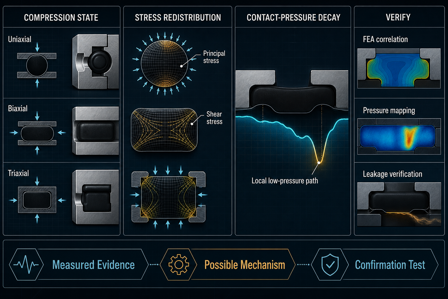
Uniaxial compression allows the rubber to expand laterally unless the test fixture prevents it. In a real seal gland, lateral expansion may be limited by groove walls, metal faces, fluid pressure and friction. Radial compression of an O-ring, axial compression of a face seal, biaxial compression in a rectangular seal and coupled radial-axial compression in a packed groove do not create the same stress field. Triaxial constraint, or a near-hydrostatic state, restricts volumetric change and increases internal pressure-like stress while reducing some forms of free lateral flow.
These constraint differences alter principal stress direction, shear stress, contact area and peak contact pressure. Local compression near a corner, parting line, extrusion gap or hard transition may relax at a different rate from the apparent global compression. Friction between elastomer and metal can lock part of the surface, delaying flow in one region while shifting stress to another. Eccentric assembly creates high-pressure and low-pressure zones that an average squeeze calculation cannot reveal.
The practical consequence is severe: the same nominal squeeze does not mean the same multiaxial stress state. A uniaxial relaxation curve cannot state which part of the seal remains loaded after thousands of hours, where the contact-pressure peak moves, or whether a low-pressure leakage path opens near a local gap.
Table 2. How Compression State Changes Stress-Relaxation Behavior
| Compression State | Dominant Constraint | Expected Stress Distribution | Seal-Level Risk | Recommended Analysis |
| Uniaxial compression | One loading axis | Broad average stress | Screening only | Material relaxation test |
| Radial compression | Bore or gland wall | Circumferential stress bias | Uneven line pressure | Section FEA |
| Axial compression | Face loading | Face pressure gradient | Gasket leak path | Pressure mapping |
| Biaxial compression | Two constrained axes | Higher shear coupling | Local set growth | Multiaxial test |
| Radial-axial coupling | Packed gland | Redistributed peaks | Extrusion or low zone | Nonlinear FEA |
| Triaxial constraint | High confinement | Hydrostatic stress component | Hidden pressure loss | Calibrated model |
| Eccentric compression | Assembly offset | Localized stress peak | Microleakage channel | Tolerance study |
Geometry, Gland Constraint and Contact-Pressure Decay: Where Material Relaxation Becomes Leakage Risk
Seal geometry determines how material relaxation becomes system behavior. An O-ring gland converts radial squeeze and gland fill into a curved contact patch. A rectangular seal may hold broader face contact but can create corner stress concentration. A flat gasket is sensitive to flange flatness, bolt load and surface roughness. A lip seal combines compression with bending, sliding and fluid pressure. A profiled seal may have ribs, cavities or hinges that deliberately redirect load.
Gland fill, extrusion gap, seal cross-section, groove width, squeeze direction, end-cap flatness and thermal expansion of mating parts all influence contact-pressure decay. Excessive initial contact pressure may accelerate relaxation, increase compression set or concentrate damage near edges. Insufficient initial pressure may fall below the sealing requirement after only modest relaxation. A local high-pressure zone can initiate tearing, scuffing or permanent deformation, while a local low-pressure zone becomes the easier path for microleakage or medium migration.
Average pressure is therefore dangerous when used alone. A seal can show acceptable average contact pressure while the minimum local pressure along one segment is already too low. Conversely, a high local peak may indicate damage risk rather than reliability margin. The relevant evidence is the distribution of contact pressure and its change over time, not merely the initial compression percentage.
Table 3. From Multiaxial Compression to Seal-System Performance
| Design or Loading Feature | Mechanical Effect | Contact-Pressure Consequence | Possible Failure Mode | Verification Method |
| High initial squeeze | High internal stress | Fast early decay | Set or cracking | Long hold test |
| Low initial squeeze | Low preload | Rapid margin loss | Microleakage | Leakage verification |
| High gland fill | Lateral flow blocked | Peak stress rise | Extrusion damage | Gland FEA |
| Large extrusion gap | Unsupported rubber | Pressure-driven flow | Nibbling or extrusion | Gap test |
| Uneven flatness | Nonuniform compression | Low-pressure segment | Face leakage | Pressure mapping |
| Friction variation | Surface locking | Stress redistribution | Local wear | Friction sensitivity model |
| Thermal mismatch | Mating-part movement | Pressure shift | Cold or hot leak | Thermal cycling |
| Eccentric assembly | Offset squeeze | Hidden weak zone | Path leakage | Tolerance stack analysis |
Mechanical Benchmark Testing and FEA Correlation: Building Evidence Beyond a Single Relaxation Curve
A reliable validation program begins with material-level uniaxial compression relaxation, but it cannot end there. Uniaxial data helps compare compounds and fit the first approximation of a viscoelastic model. Biaxial or multiaxial coupon tests add constraint effects. Actual seal cross-section tests reveal shape-dependent deformation. Finished-seal-in-gland testing captures friction, gland fill, surface condition and assembly tolerance.
Useful measurements include constant-deflection and constant-load tests, load-displacement-time curves, pressure-sensitive film, pressure mapping, pressure decay, leakage verification and pressure recovery after thermal cycling. Comparisons should include different pre-compression histories, loading rates and temperatures where service conditions justify them. Results are affected by specimen geometry, compression direction, surface state, material batch and measurement timing.
Finite element analysis is valuable when it combines hyperelasticity for large deformation with viscoelasticity for time-dependent response. Yet FEA predictions must be calibrated against measured contact pressure and leakage behavior in the actual seal geometry. A model fitted only to uniaxial data may reproduce a material curve while missing local multiaxial pressure redistribution inside the gland.
Engineering Controls and Material Selection: Designing for Retained Contact Pressure, Not Just Initial Squeeze
Engineering control starts by selecting material and hardness for the actual compression state, not for a catalog number alone. Compression set is useful, but it should not be the only selection criterion. The gland, finished seal, mating parts and service medium must be tested as a system. Squeeze ratio, gland fill, extrusion gap, surface roughness and friction condition should be controlled so that the design avoids both unnecessary over-compression and insufficient long-term preload.
Uniform end-face support and side-wall constraint reduce unintended stress concentration. Eccentricity, assembly error and end-cap deformation should be included in tolerance analysis. Temperature and medium exposure must be evaluated because they can change viscoelastic relaxation, modulus, friction and permanent deformation. Pre-compression or pre-cycling may be useful when verified, but it is not a substitute for long-term hold, thermal cycling and leakage verification.
Acceptance limits should be tied to the seal structure, fluid pressure, medium, temperature, assembly tolerance and failure consequence. Material batch, cure state, hardness, dimensions and test conditions should be recorded so that model predictions can be correlated with measured contact pressure and observed leakage results.
FMEA Risk Analysis: Failure Modes Created by Misreading Multiaxial Relaxation
Validation should still move from material specimen testing to multiaxial coupon work, seal-section checks, finished-gland measurement, calibrated FEA and leakage verification. No single level proves everything. The FMEA below focuses on where simplified assumptions hide multiaxial behavior, local contact-pressure decay or surface-friction effects. Numerical RPN is not used because risk depends on seal structure, material, temperature, pressure, assembly constraint and failure consequence.
Table 4. FMEA for Multiaxial Stress Relaxation in Rubber Seals
| Failure Mode | Cause | Local Effect | System Effect | Detection Method | Control Action |
| Single-axis data used alone | Oversimplified assumption | Wrong pressure estimate | Hidden leak risk | Model review | Add multiaxial validation |
| Excessive initial compression | High squeeze | Fast relaxation or set | Damage or pressure loss | Hold test | Reduce peak strain |
| Insufficient initial compression | Low preload | Early low-pressure zone | Microleakage | Leak test | Adjust gland design |
| Uneven radial and axial constraint | Tolerance stack | Pressure redistribution | Local leakage | Pressure map | Improve alignment |
| Local stress concentration | Corner or gap | Material damage | Extrusion or crack | FEA and inspection | Smooth transitions |
| High gland fill | Blocked flow | High internal stress | Set or extrusion | Gland review | Control fill ratio |
| Thermal acceleration | High temperature | Faster decay | Reduced margin | Thermal hold | Validate service range |
| Uncalibrated FEA model | Wrong material input | False confidence | Design escape | Correlation test | Fit to real data |
| Friction ignored | Surface locking | Shear bias | Pressure error | Sensitivity study | Control surface state |
| Average pressure hides decay | Coarse measurement | Low zone missed | Leak path remains | Local mapping | Use minimum pressure criterion |
Conclusion: Long-Term Seal Reliability Requires Multiaxial Evidence
Rubber seal stress relaxation is not determined by material name or hardness alone. The long-term sealing result depends on multiaxial compression state, gland and mating-part constraint, squeeze, gland fill, loading history, temperature, medium, friction, surface condition, seal geometry and the distribution of contact pressure over time. Uniaxial compression relaxation data is valuable for screening and initial finite element model fitting, but it cannot replace verification of the actual constrained seal structure. Reliable design requires correlation among material testing, multiaxial analysis, finished-seal contact-pressure measurement and leakage verification. The engineering target is not merely to start with high compression; it is to retain sufficient local contact pressure throughout the defined service condition.
FAQ: Multiaxial Stress Relaxation in Rubber Seals
Q:What is the difference between stress relaxation and compression set in a rubber seal?
A:Stress relaxation is stress reduction under approximately held strain. Compression set is unrecovered deformation after unloading. A seal may relax during service even before visible permanent deformation is measured, so compression set cannot be used as a direct substitute for contact-pressure retention.
Q:Why does multiaxial compression produce different relaxation behavior from uniaxial compression?
A:Multiaxial compression changes lateral flow, principal stress, shear stress and volumetric constraint. Rubber in a groove cannot deform like a simple uniaxial specimen. The resulting contact-pressure decay depends on constraint, friction and geometry, not only on material viscoelasticity.
Q:Can a material with good compression-set performance still show contact-pressure loss?
A:Yes. Good recovery after unloading does not prove that contact pressure stayed high during loading. Contact pressure may decay through stress relaxation, mating-part movement, uneven constraint or frictional redistribution even when measured compression set appears acceptable.
Q:How does gland constraint affect stress relaxation in an O-ring?
A:Gland constraint limits lateral expansion and redirects stress through the O-ring cross-section. Higher fill, extrusion-gap geometry and wall friction can shift pressure peaks and low-pressure zones. The same squeeze can therefore produce different long-term sealing margins in different glands.
Q:Can finite element analysis predict long-term contact-pressure decay?
A:Finite element analysis can support prediction when the hyperelastic and viscoelastic material models are calibrated to relevant test data and the actual gland, friction, temperature and loading history are represented. It should be confirmed against measured contact pressure and leakage behavior.
Q:Which test is more useful: material compression relaxation or finished-seal leakage testing?
A:They answer different questions. Material compression relaxation helps compare compounds and fit models. Finished-seal leakage testing confirms system function. A robust program uses both, with intermediate contact-pressure or pressure-mapping evidence to connect material response to seal performance.
Q:Should seal compression be reduced to minimize stress relaxation?
A:Not automatically. Reducing compression may lower initial stress, but it can also reduce sealing margin. The correct compression range must be defined by geometry, medium, pressure, temperature, tolerance, contact-pressure retention and leakage verification, not by relaxation avoidance alone.
Post time: Sep-10-2026