
Executive Summary
In a modulating control valve, the moving trim element and its seal interface form one coupled mechanical boundary. Position changes, repeated reversals, lateral movement, tilt or unstable control and flow conditions can change seal contact over time. “Spool” is used here as a working term for the moving trim element; the actual valve architecture, motion type and seal location must be confirmed before an application-specific conclusion is made.
Oscillation is not one failure mechanism. It may involve control-loop hunting, actuator or positioner response, friction-induced stick-slip, mechanical clearance, pressure loading or flow-related instability. A small repeated displacement may repeatedly slide one contact band, while eccentric or tilted motion may unload one region and overload another. Possible consequences include friction variation, wear, scoring, particle generation, material deformation, heat or a leakage pathway. These are conditional mechanisms, not confirmed field findings.
Seal-contact stability is therefore a time-dependent system question. Geometry, guiding, clearance, alignment, pre-compression, material condition, pressure, fluid properties, actuator behavior and control response must be considered together. A stable command or feedback signal does not prove stable contact, and no observed leak does not prove uniform contact pressure. Structural inspection, synchronized motion and process records, leakage or functional evidence, seal inspection and repeatability testing each confirm only a defined part of the chain.
Control-Valve Spool and Seal-Interface Architecture
The first design question is which relative motions the assembled interface permits and which it is intended to constrain. A moving trim element may travel linearly, rotate or operate in a guided arrangement, with the seal located at a stem, moving element, sleeve, end face or another interface. Without the actual cross-section and assembly definition, these alternatives must remain open.
The relevant boundary is the assembled, loaded and operating condition. Nominal clearance and seal compression do not show alignment under load, guide wear, thermal expansion, pressure deflection or reversal path. Radial offset, tilt or clearance change can move the contact band. Conceptually, local pressure q(x,t) varies with position and time. A simplified friction model is F_f = muN, where mu is an effective coefficient and N is normal load; local load, contact area and surface condition may all change during oscillation.
Control demand, actuator output and actual trim position are separate signals. Stable feedback may coexist with local clearance movement, while a fluctuating trace may reflect sensor behavior rather than seal motion. The review must identify the moving element, guides, measurement point and contact zone.
Table 1 – Valve and Seal-Interface Features That Influence Contact Stability
| Structural or Motion Feature | Possible Contact Mechanism | Effect on Seal Interface | Potential Engineering Risk | Recommended Check |
| Moving-element path | Linear, rotary or compound motion creates different loading patterns | Contact movement cannot be inferred from command alone | Incorrect mechanism attribution | Confirm kinematic path and seal location |
| Guide clearance or wear | Lateral movement, tilt or impact during reversal | Local unloading and overload | Uneven wear or leakage pathway | Inspect guide condition and clearance |
| Alignment or eccentricity | Non-uniform radial or angular displacement | Contact band migrates | Localized wear or extrusion tendency | Check alignment, runout and contact pattern |
| Pre-compression and fit | Deformation or ageing changes available contact load | Reduced sealing margin or increased drag | Leakage risk or friction instability | Verify assembled fit and actual seal design |
Oscillation Mechanisms and Contact-Pressure Redistribution
Normal modulation is an intended position change without repeated unintended reversal. Controlled micro-motion does not automatically indicate instability. Control-loop hunting is repeated correction involving process dynamics, controller behavior, actuator response, measurement and delay. Stick-slip alternates between sticking and rapid sliding. Flow-induced movement may involve changing fluid forces or pressure distribution, but flashing, cavitation, resonance or another specific cause requires supporting evidence.
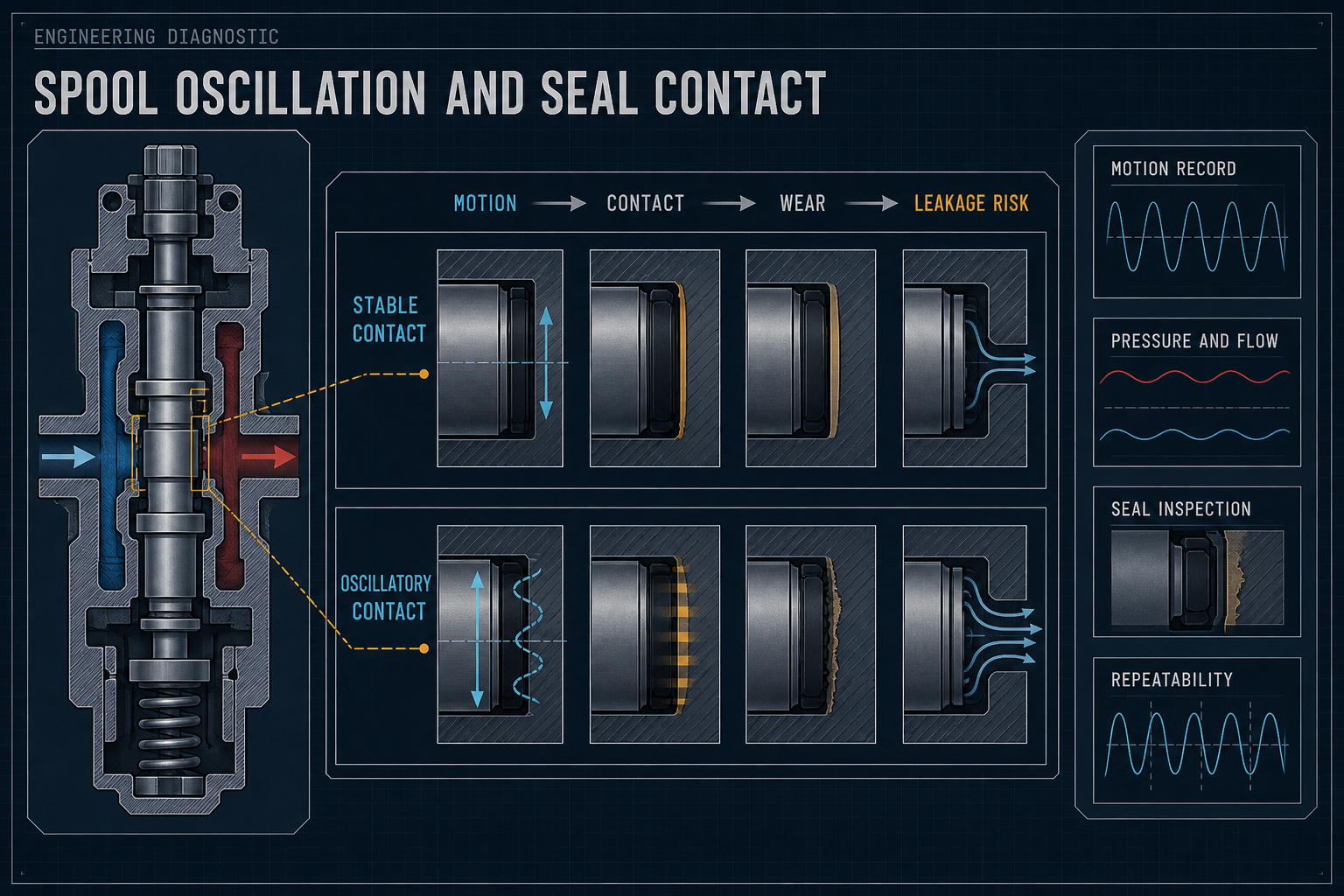
The central mechanism is time-varying relative displacement. Reversal changes shear direction; tilt or lateral shift may unload one side while increasing local pressure on another. Friction can feed back into motion: increased drag may require more actuator force, and delayed or excessive compensation may produce overshoot and reversal. Pressure across the moving element may also change axial or radial loading. A pressure record alone does not establish a contact change; it must be correlated with motion, contact evidence or functional response.
Table 2 – Oscillation Mechanisms and Their Evidence Requirements
| Suspected Mechanism | Typical Observable Signal | Possible Seal-Contact Effect | Required Confirmation | Interpretation Boundary |
| Control-loop hunting | Repeated command and feedback corrections | Repeated sliding or reversal | Synchronized command, feedback, process and actuator records | Command fluctuation does not prove equal seal displacement |
| Actuator or positioner instability | Delay, overshoot or repeated output correction | Variable speed and reversal load | Output and actual trim-position measurement | Output does not define contact pressure |
| Stick-slip | Alternating hold and rapid displacement | Transient shear and contact redistribution | Time-resolved displacement and load-related evidence | Distinguish motion from sensor noise |
| Mechanical-clearance movement | Position variation with limited command change | Tilt, lateral shift or intermittent contact | Clearance, guide, alignment and contact inspection | Stable feedback can coexist with local movement |
Seal Contact, Wear and Leakage-Risk Pathways
The engineering chain is: oscillatory motion → changing contact state → friction or wear mechanism → possible leakage or service consequence → required evidence. Repeated reversals may increase sliding, but wear also depends on load, speed, surface condition, fluid or lubrication behavior, material compatibility and particles. No universal wear rate or service-life conclusion follows from oscillation alone.
Uniform wear and localized damage have different implications. A broad contact-band change may reflect distributed sliding, while a narrow score, one-sided polish mark, cut, extrusion feature or transfer deposit may indicate local load, debris or misalignment. Compare the observation with motion path, pressure direction and seal geometry. A removed seal may relax, so its appearance is condition evidence rather than a full reconstruction of loaded contact.
Contact loss may be intermittent: the interface can function under one state yet leak under another. Excessive contact may increase friction, heat and deformation before a leak appears. Material change can alter fit and friction, but does not prove an oscillation cause. Static leakage testing has limited scope because dynamic contact may differ.
Operating, Control and Fluid Variables
Record position, displacement, speed, reversals, pressure, differential pressure, flow, temperature, fluid properties, controller output, actuator response and feedback. Ask whether each change coincides with repeatable motion, leakage, force or surface evidence. Pressure fluctuation without measured motion does not establish seal damage; motion without a pressure event still requires separation of control, actuator, friction, clearance and alignment causes. Measurement location and sampling must resolve the motion being investigated.
Table 3 – Operating Variables and Dynamic-Seal Response
| Operating or Control Variable | Possible Influence on Valve Motion | Possible Seal Response | Risk Indicator | Verification Method |
| Command and feedback | Reversal, delay or overshoot | Repeated sliding or unmeasured movement | Mismatch with actual response | Synchronized command, feedback and motion record |
| Displacement and reversal count | Changes sliding distance and shear direction | Contact-band migration or wear | Repeatable motion with condition change | Motion linked to leakage or inspection |
| Pressure and differential pressure | Changes loading and holding force | Redistribution or intermittent unloading | Motion or leakage coincident with pressure | Synchronized pressure and displacement |
| Alignment, guides and clearance | Permits shift, tilt or impact | One-sided contact or scoring | Contact pattern differs from nominal | Dimensional, guide and seal inspection |
Characterization and Benchmark Testing
Begin with the assembled architecture: moving element, guides, seal position, intended motion, clearance, alignment, pre-compression, pressure boundary, surface condition and debris paths. If the seal is removed, record orientation and contact features before handling changes the evidence. A drawing alone does not prove loaded contact.
Record command, actuator or positioner output, feedback and, where possible, independent displacement with pressure, flow, temperature and load signals on a common time base. Analyze reversals and speed; correlate leakage or function with position and pressure; inspect seals, counter-surfaces and guides for scoring, transfer, extrusion, cracking, particles or altered shape. Baseline and repeat-cycle evidence help distinguish causes.
Validation Path for Oscillation-Related Seal Contact
Architecture and geometry — Confirm structure, motion type, seal location, guides, clearance, alignment, pre-compression and surface condition. This establishes the mechanical boundary, not dynamic stability.
Motion and control characterization — Correlate command, actuator output, feedback and actual movement. This defines measured motion, not contact pressure or damage by itself.
Fluid and load correlation — Compare motion with pressure, differential pressure, flow, temperature and fluid-state records. Correlation does not identify a unique cause.
Seal-condition and leakage evidence — Combine defined functional or leakage observations with contact and material inspection. One result does not cover untested states.
Repeatability and change control — Repeat cycles and reassess after maintenance, ageing, material, control or operating changes. This validates only the represented configuration.
Engineering Controls and Maintenance Strategy
The first control layer is structure and interface: verify guidance, clearance, alignment and pre-compression; control eccentricity, surface damage, burrs, contamination and fit changes; and inspect the contact path. Where lateral or angular motion is possible, evaluate contact redistribution rather than average compression alone.
The second layer evaluates the actual seal compound, surfaces and fluid against pressure, temperature, friction and motion history. Assess swelling, hardening, compression set, cracking, extrusion, transfer and debris. Compatibility is not proof of dynamic contact stability.
The third layer covers controller tuning, actuator response, positioner behavior, measurement and filtering. Trend command, feedback, pressure, flow and condition indicators. Define triggers for unexplained reversals, contact drift, leakage change, increased actuation demand or debris. Record maintenance state, inspect removed parts before cleaning changes the evidence, and confirm motion and function after reassembly. Reassess after relevant architecture, material, fluid, control or alignment changes.
Increasing actuator force or control aggressiveness should not mask an unknown mechanism. It may reduce visible position error while increasing friction, contact load or reversal frequency. Identify the cause, control the relevant variable and verify the resulting condition.
FMEA Risk Analysis
This is a qualitative FMEA without RPN. Risk depends on architecture, seal form, motion, pressure, fluid, material state, control behavior, consequence and evidence. Entries describe conditional pathways, not confirmed failures.
Table 4 – FMEA for Oscillation-Related Seal Contact Risk
| Failure Mode | Cause | Local Effect | System Effect | Detection Method | Control Action |
| Oscillatory micro-motion at interface | Control correction, actuator response or clearance | Repeated sliding or reversal | Friction drift, wear or unstable sealing | Synchronized command, feedback and motion | Identify and control physical motion cause |
| Local contact-pressure redistribution | Guide clearance, tilt, eccentricity or pressure change | One-sided unloading or overload | Intermittent leakage or local wear | Alignment, contact and load correlation | Control guidance, alignment, clearance and fit |
| Stick-slip instability | Friction variation or control compensation | Hold-and-release displacement | Transient contact load and position instability | Time-resolved motion and load evidence | Investigate friction and control response |
| Seal wear, scoring or extrusion | Sliding, local load, roughness, debris or changed fit | Damaged or displaced barrier | Leakage, particles or increased friction | Seal, counter-surface and debris inspection | Control surfaces, debris, fit and motion |
| Material-related fit change | Fluid exposure, temperature, ageing or cycling | Changed friction, area or pre-compression | Leakage or motion sensitivity drift | Material comparison and dimensional inspection | Confirm compound compatibility and reassess fit |
| Unrecognized instability or false stability | Wrong attribution, inadequate sampling or one signal | Local motion or cause remains hidden | Unrecognized degradation | Multi-channel records plus structural evidence | Define measurement limits and combine methods |
| Post-maintenance contact change | Misalignment, seal damage or foreign material | Changed friction or contact pattern | Early leakage or repeat failure | Assembly and post-maintenance inspection | Controlled assembly and functional check |
| Operating change without reassessment | Fluid, pressure, temperature, control or material change | Changed load or material response | Unconfirmed contact stability | Change-control review and comparison | Define triggers and verify new configuration |
Conclusion
Control-valve spool oscillation is a coupled motion, load, friction, material and sealing problem. Reversal, stick-slip, guide clearance, alignment error, pressure variation, actuator response and flow-related loading may alter time-dependent seal contact, but the responsible mechanism must be established from evidence. A defensible assessment combines architecture, synchronized motion and process records, seal and surface condition, leakage or functional response and repeatability after relevant changes. The conclusion remains bounded by the actual valve structure, seal form, material, fluid, operating envelope and test evidence.
FAQ: Control-Valve Spool Oscillation and Seal-Contact Validation
These questions address design, diagnosis and validation when a modulating valve shows repeated movement or changing sealing behavior. Conclusions depend on the actual architecture, seal, fluid, control response and measurement method.
Q:What is control-valve spool oscillation?
A:It is repeated or unstable movement of a moving trim element around an intended position or path. It may involve control hunting, actuator response, stick-slip, clearance, pressure loading, flow forces or measurement artifacts; the physical cause must be confirmed.
Q:How can spool oscillation change dynamic seal contact?
A:Repeated displacement changes sliding direction, contact-band location and friction history. Lateral shift or tilt can unload one region and increase local pressure elsewhere. The effect depends on geometry, pre-compression, guidance, alignment, loading, surface condition and measured motion.
Q:Is valve hunting the same as spool vibration?
A:No. Hunting describes repeated control correction or process response; physical trim movement must be measured. A fluctuating trace does not prove equal movement at the seal, and local movement may occur with limited change in reported position.
Q:Can oscillation cause seal wear or leakage?
A:It can be associated with wear or leakage when repeated sliding, local loading, debris, material change or intermittent contact reduces barrier continuity. Motion, pressure, material condition and surface evidence are required before assigning causation.
Q:Which operating variables should be recorded?
A:Record command, actuator or positioner output, position feedback, actual displacement where available, pressure, differential pressure, flow, temperature, relevant fluid condition and load-related signals. Document measurement location, timing and limits.
Q:How can oscillation damage be distinguished from material ageing?
A:Compare motion and operating history with seal condition. Local scoring, one-sided wear, transfer, extrusion or debris may support a motion-related pathway, while swelling, hardening, cracking or compression-set-related fit change may support material change. One visual feature is rarely conclusive.
Q:What evidence is needed to validate seal-contact stability?
A:Start with architecture and geometry, correlate measured motion with control and fluid variables, examine seal condition and leakage or function, and repeat after relevant changes. Stable feedback or one leakage check is not complete validation.
Q:When should a valve seal be inspected, replaced or revalidated?
A:Reassess when unexplained motion, leakage change, increased actuation demand, contact drift, scoring, extrusion, debris, material change, maintenance disturbance or operating-condition change is observed. Criteria must fit the actual valve, seal, fluid and operating envelope.
Post time: Sep-21-2026